Guide that even beginners can easily create original PCs [Hardware Assembled Edition]

Many people start new life such as admission and joining in April, and there are many people who want to replace them with new PCs in the new season. However, PCs with more advanced commoditization are similar if they think about getting one of their favorite, they do not know if it is a notebook PC, and in the case of a desktop PC, a lineup of famous manufacturer's PCs Is poor, there are no options as there are no new products themselves in the first place. Services that can be assembled with parts specifiedBTOAlso the width of parts selection seems to be wide, narrow, it is also an aspect that it does not reach the itchy place. "Well, if you do make it yourself, you just have to create it yourself", it is a great opportunity to challenge yourself PCs.
Thanks to the progressive integration of chips into the motherboard, the hurdles of assembling PCs has dramatically declined, and tools that are used thanks to toolless parts design are also easier than the plastic model with only "+ driver" About Thanks to improved parts performance, it is also possible to assemble a compact, high-performance PC that could not be thought of before a long ago. A unique PC case is more deliberate and can satisfy the wish "I want a PC different from a person".
Furthermore, by making a PC yourself, you can experience "This computer is like this" and change the parts each time you find what you want to do to upgrade your computer's knowledge I got acquainted and became a study by studying. So, the way to make a self-made PC for the commitment school who want to choose a desktop type PC "I dare want to choose one of my own colors" in the era of mobile terminal in the age of mobile terminal is said to be laptop PC Like this. In the same way while looking at the review article, beginners can easily complete the PC.
◆ Basic Part 1: Motherboard
My original PC is "MotherboardMounting various parts (parts) on the main board called "Make it." This time, ASUS's motherboard "H97I-PLUS"Was chosen. Small Mini-ITX size with M.2 slot and despite H series CPUOverclocking(OC) corresponding to the fact that it is big.
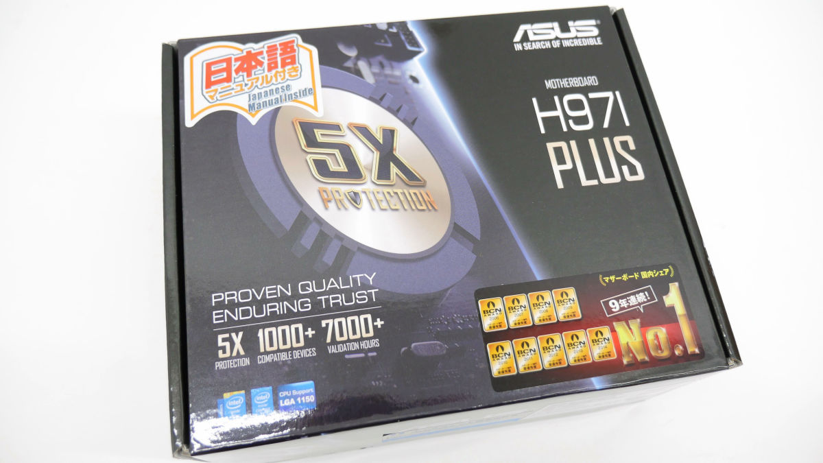
The contents of the box are motherboard, SATA cable × 2, back panel, install DVD, instructions.
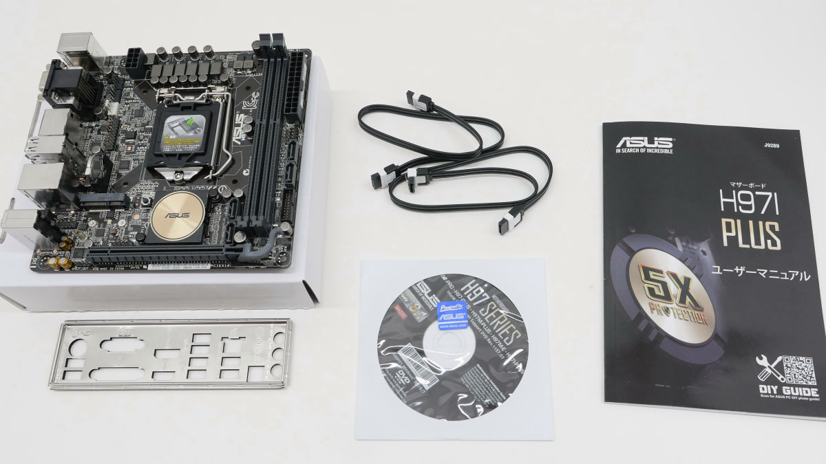
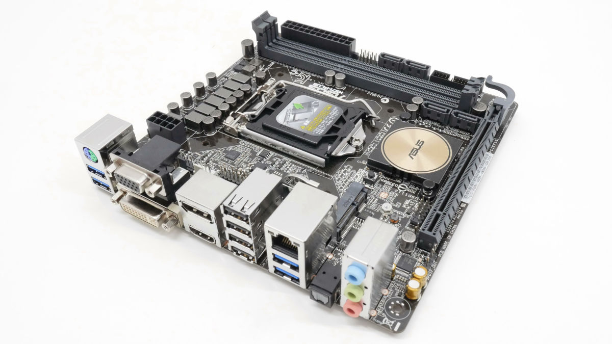
This is the motherboard H97I-PLUS. The size is 17 cm × 17 cmMini-ITXstandard. Compact size compared to general motherboard.
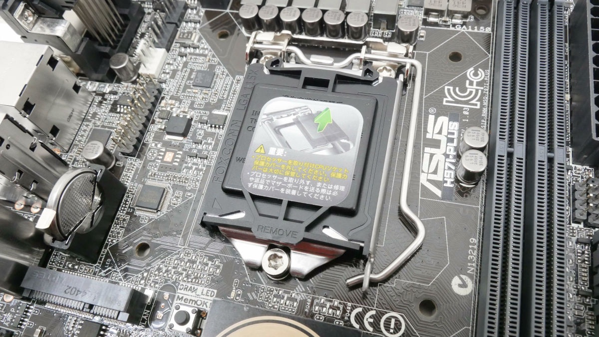
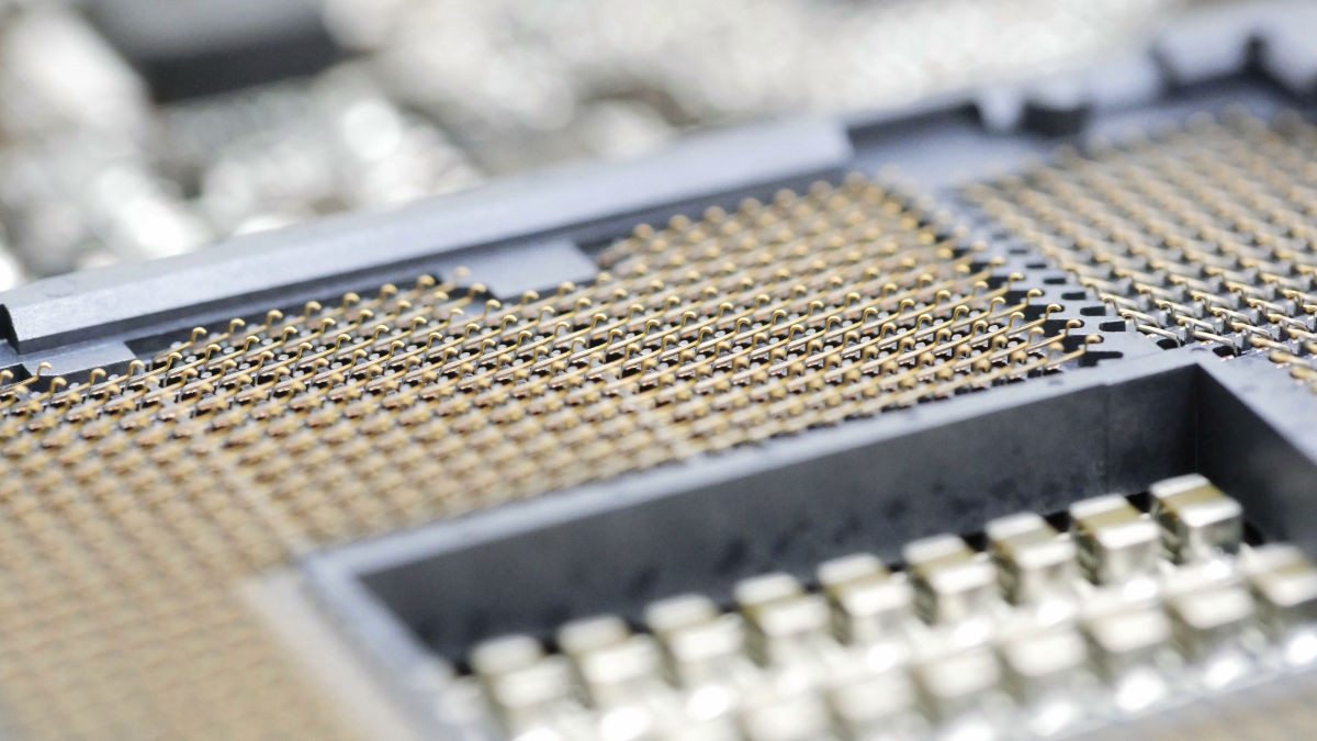
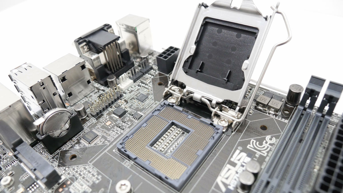
This is a CPU socket. H97I-PLUS is "LGA 1150"Intel CPU can be installed.
When unlocking with a lever and opening the CPU socket, it feels like this.
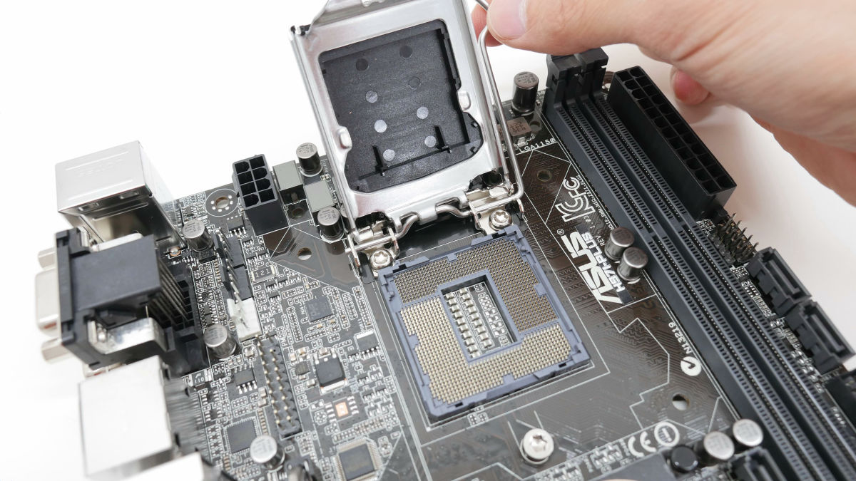
There are 1150 fine pins in the socket.If this pin bends or breaks it will not be able to recognize the CPU and the motherboard will be unusable so be careful not to touch it.
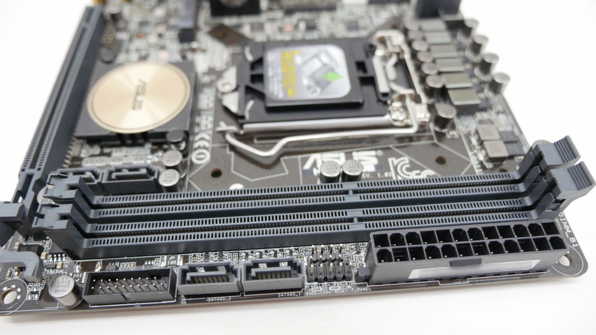
This is a memory slot. H97I-PLUSDDR 3It corresponds to the memory of the standard. In front of the memory slot, from left USB3.0 connector (20-1 pin), SATA port × 2, system panel connector, power connector (24 pins).
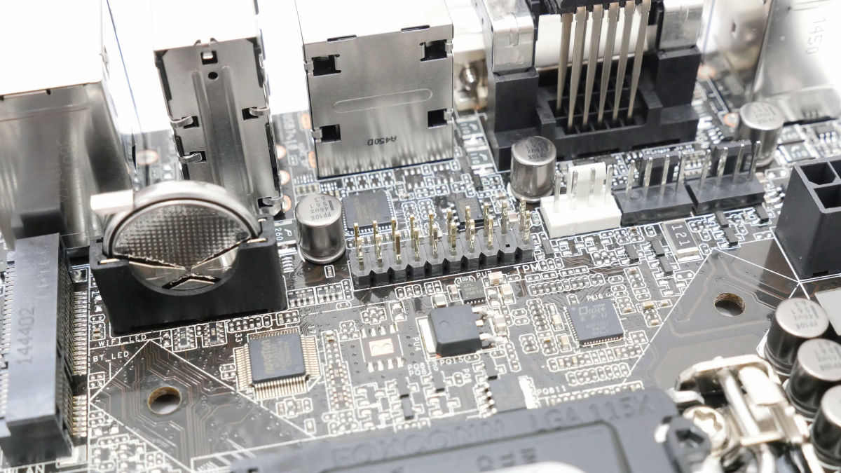
TPM header pin on the side of the button battery, white CPU fan connector on the right, black fan connector × 2.
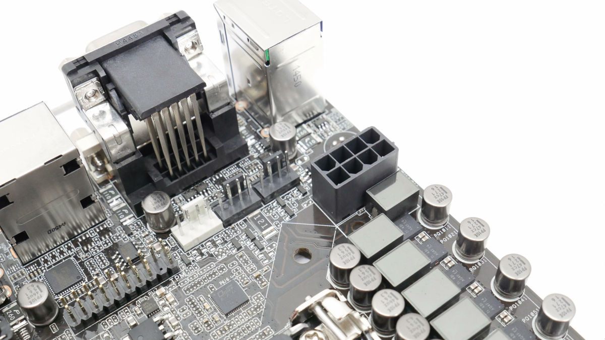
Red frame is auxiliary power connector.
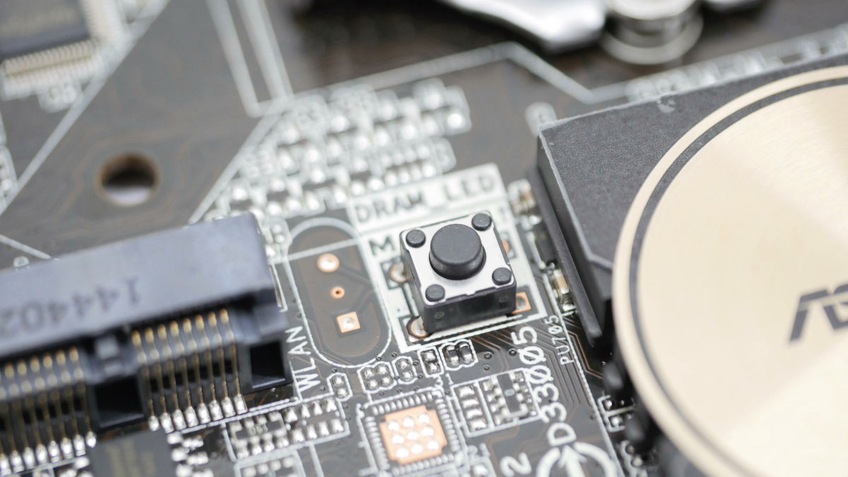
"MemOK!" Button to increase memory compatibility. Use it when using OC memory.
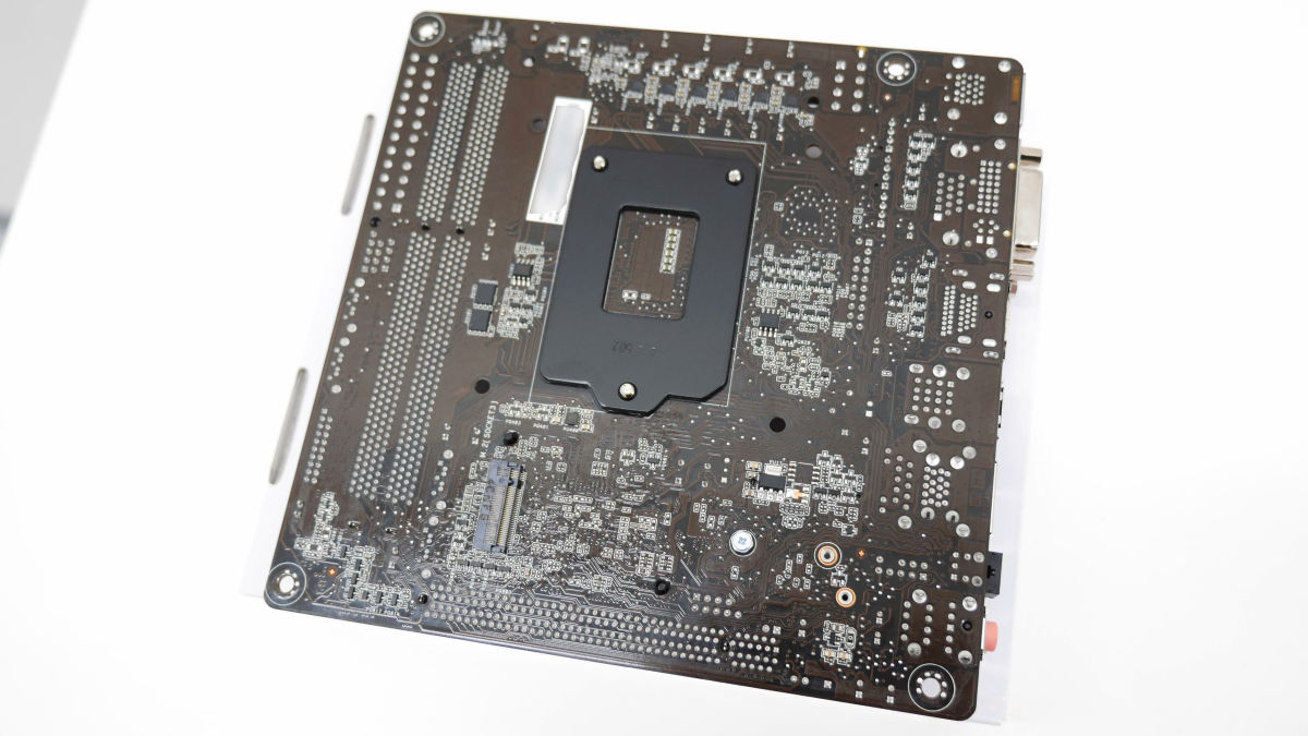
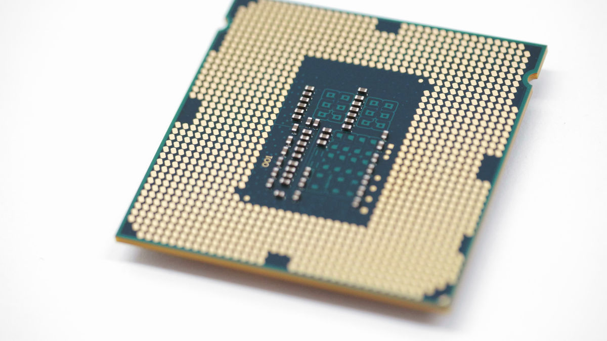
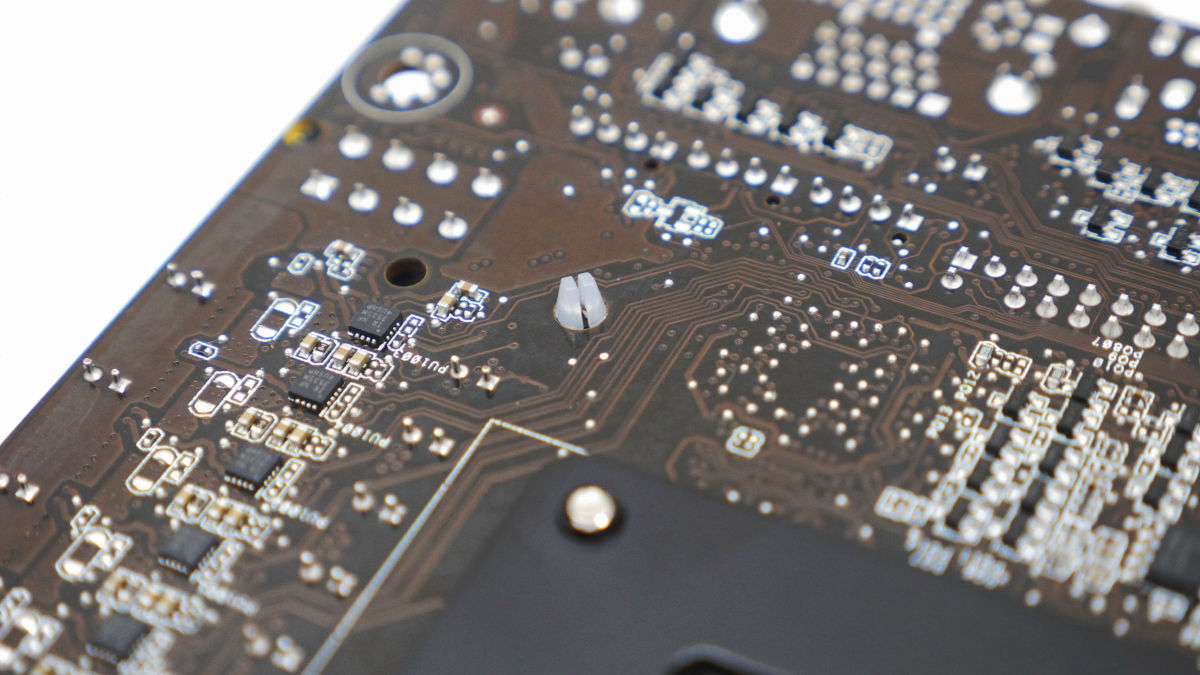
The back side looks like this. Dark brown color of the substrate color which is like ASUS mother board.
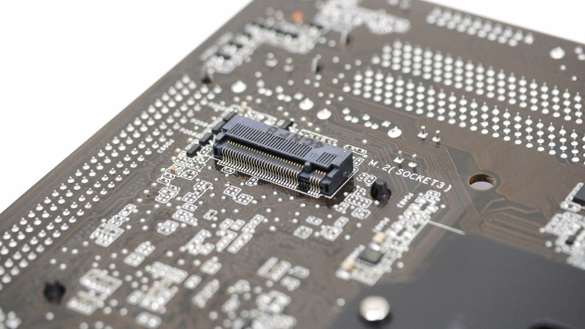
M.2 slot on the back of the motherboard. More than SATA 3M.2This slot will be effective when using the standard high speed SSD.
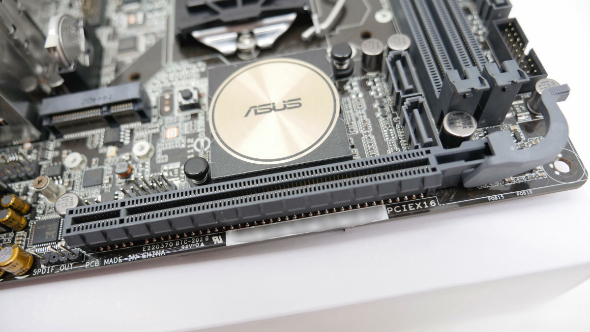
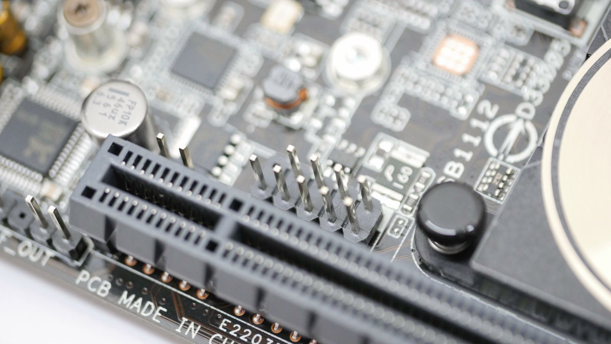
Under the golden heat sinkIntel H97 chipsetthere is. Add a graphic board etc below itPCI-Express (× 16)slot.
Header pin for USB 2.0 next to the PCI - Express slot. Connect with the front panel of the PC case and use it.
Front audio header pin which connects to earphone / microphone on I / O part of back panel.

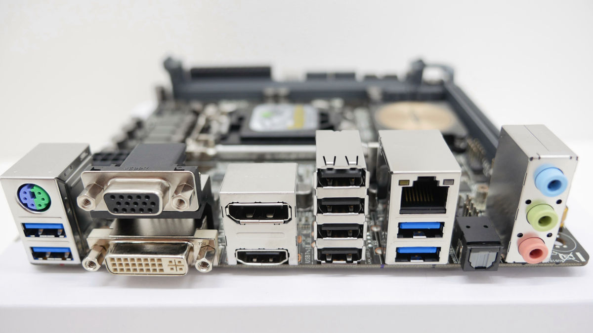
Around the I / O port is like this. From PS / 2 port · USB 3.0 port, VGA output · DVI output, DisplayPort output · HDMI output, USB 2.0 × 4, LANG port · USB 3.0 × 2, optical digital S / PDIF output, line input ) · Line output (green) · Microphone (pink).
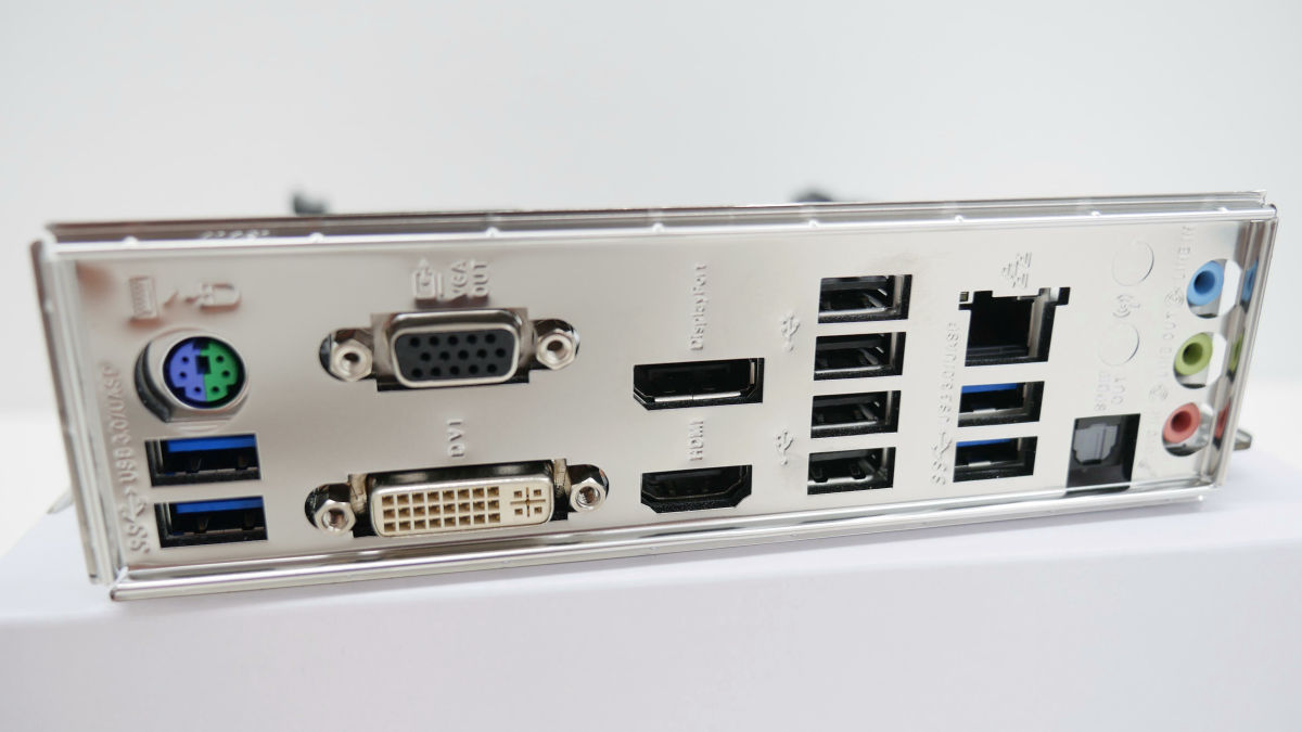
When installing the PC case, we will install this back panel attached to the motherboard so it will be like this.
◆ Basic Part 2: CPU
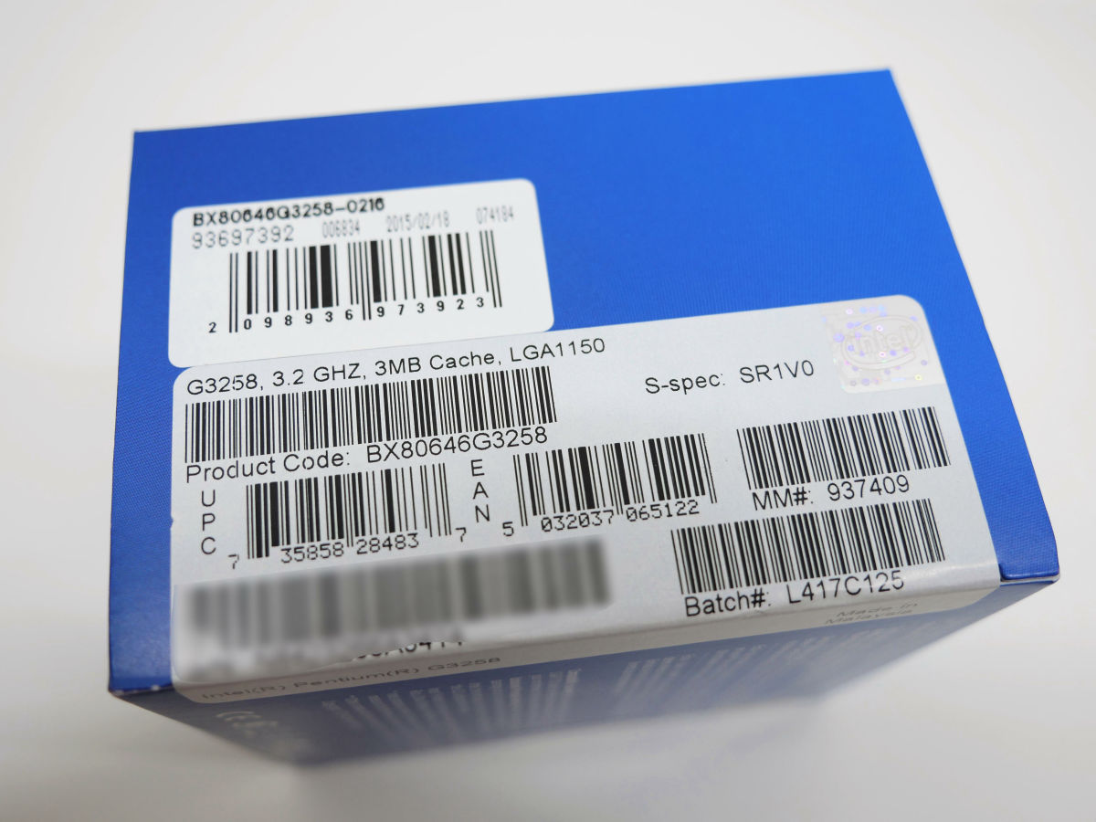
First of allCPUWe will install it on the motherboard. This time a commemorative model of the 20th anniversary of Pentium's birth "Pentium G 3258"Is used. Despite being less than 10,000 yen, the OC exceeding 4 GHz has become the best seller in terms of victory.
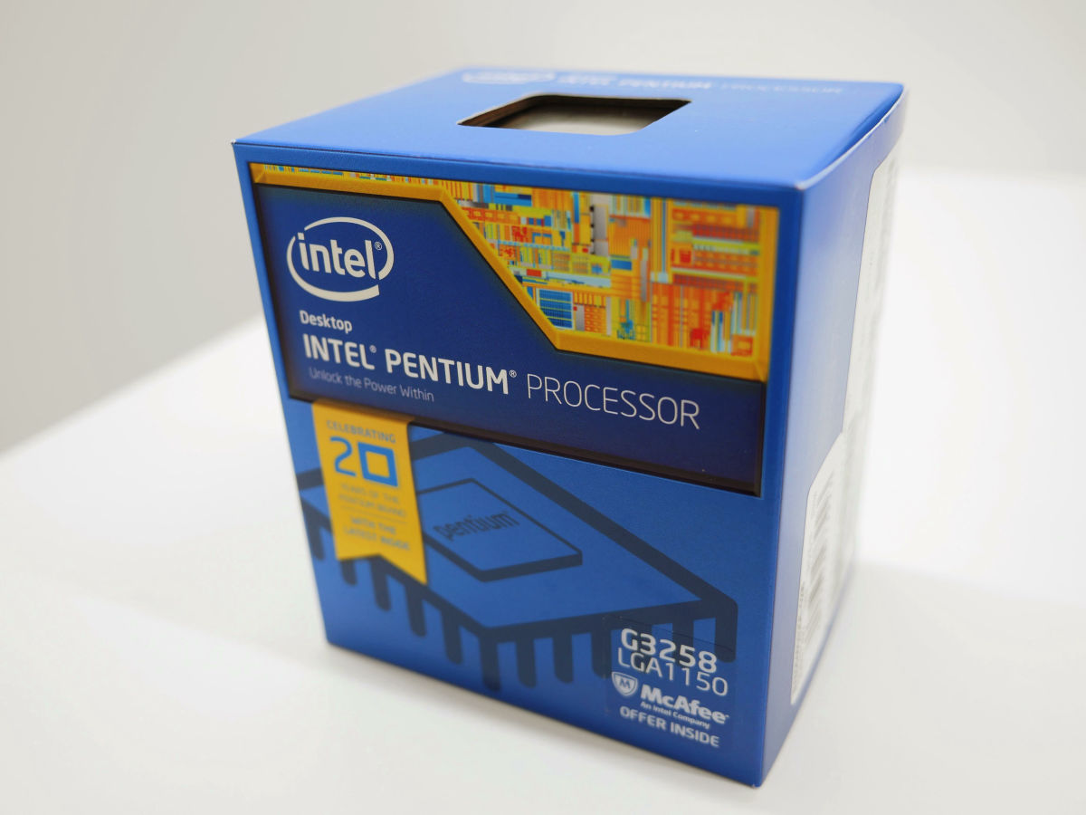
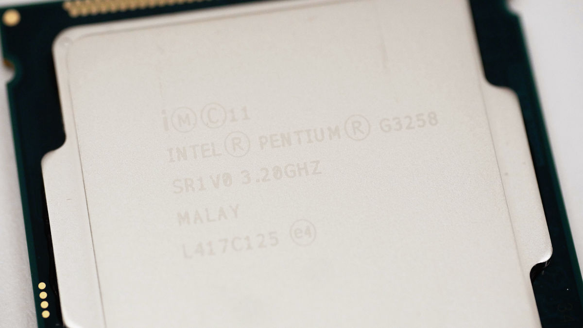
S-specIs "SR 1 V 0"
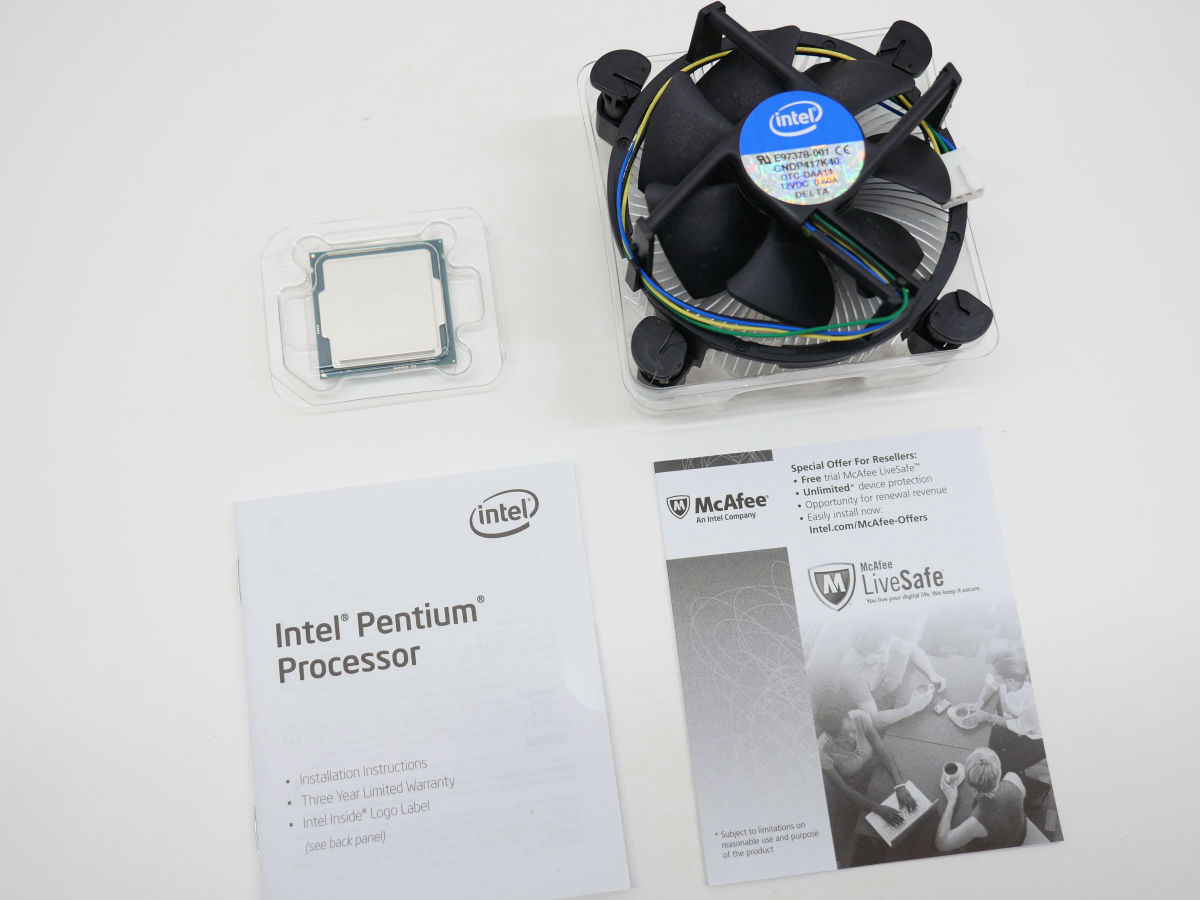
The contents of the box are CPU, CPU cooler, instructions etc.
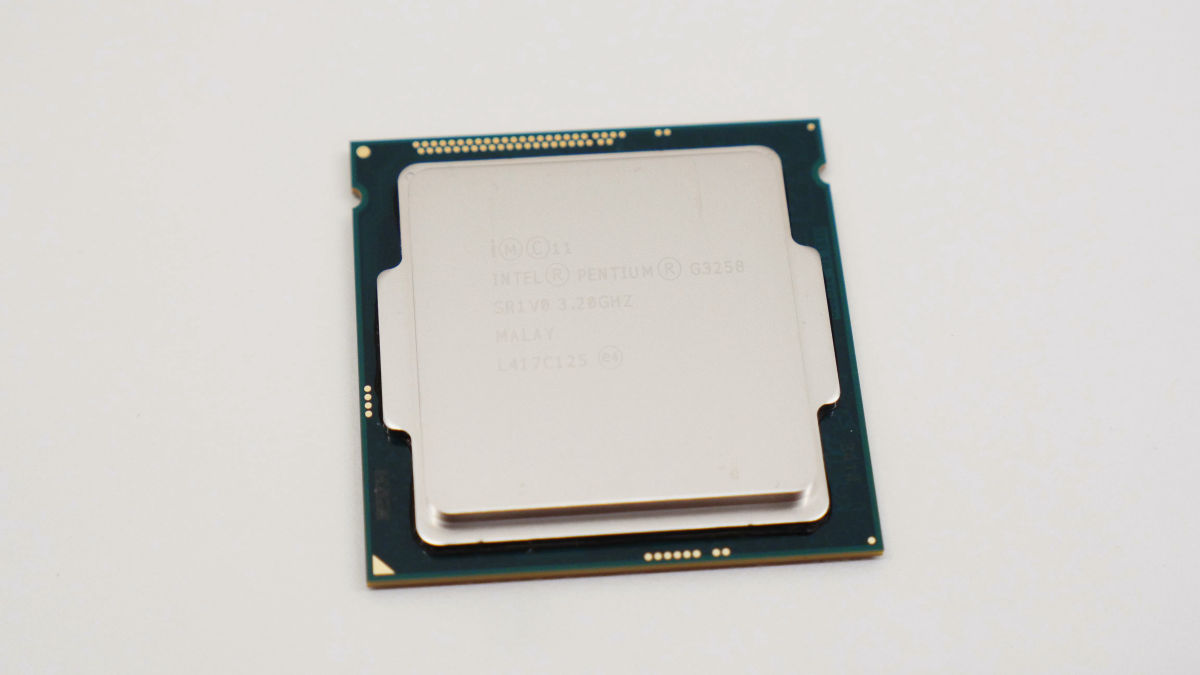
This is CPU. Silver parts protect the CPU coreHeat spreader.
The lot number was "L417C125". The lot number is a measure to examine models with high OC resistance.
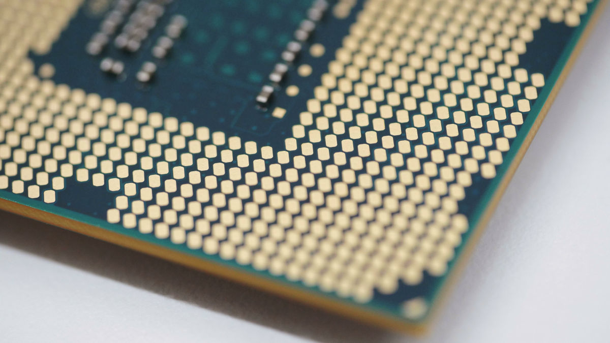
The back side looks like this. There are no pins, only contacts.
A fine pin of the motherboard comes into contact with this contact.
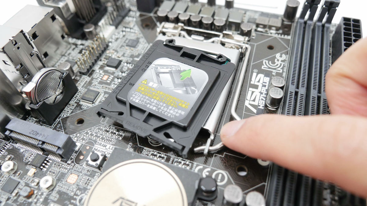
That's why CPU mounting work. First open the CPU socket cover of the motherboard ......
Gently place the CPU on the pins.
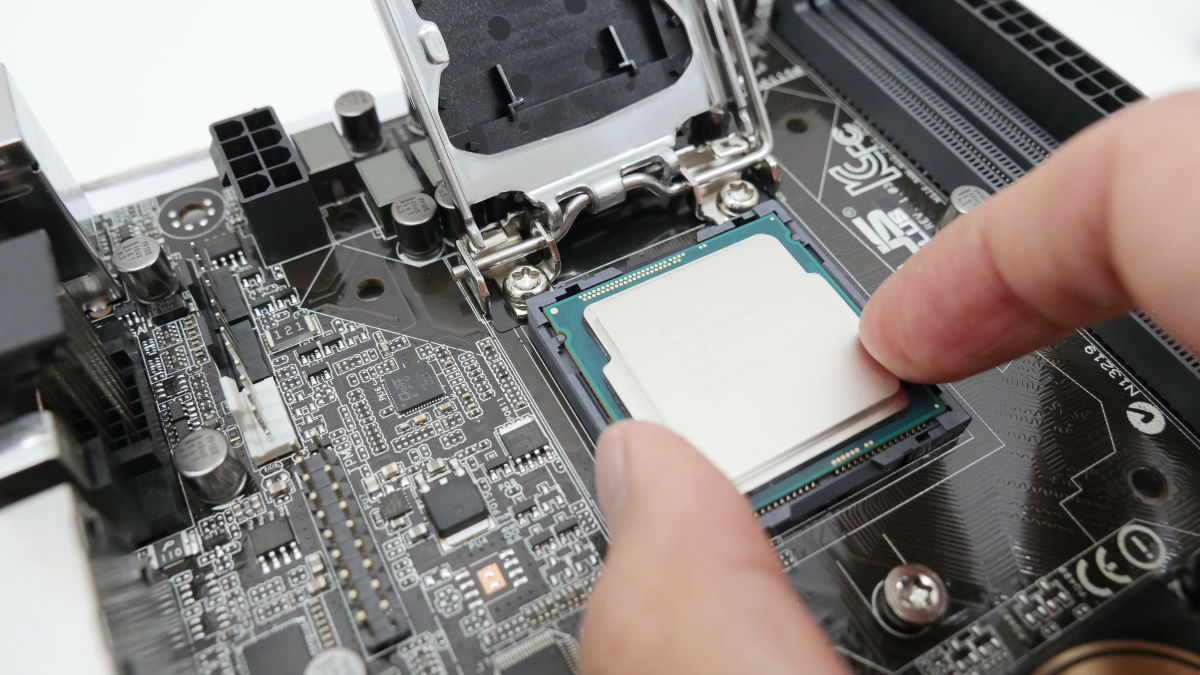
Since there is a direction, it is the point that matches "notch".
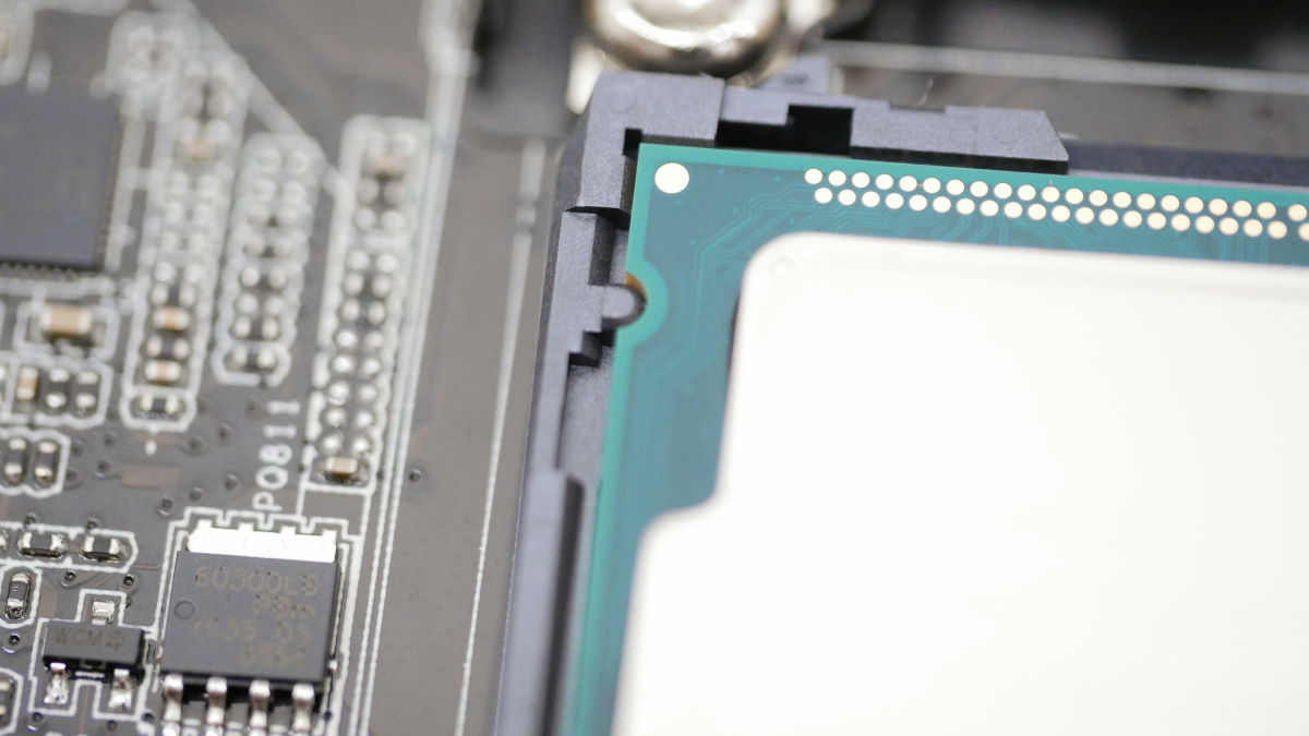
Close the socket cover, put the metal hook under the screw ... ....
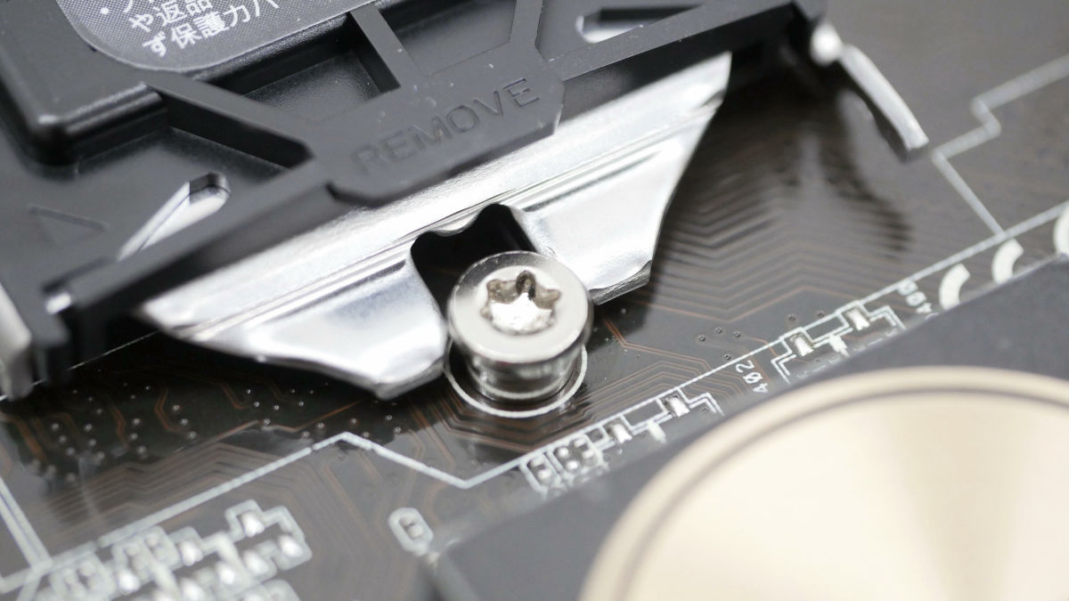
Lower the lever "A!" And lock it. Correct answer is that the click and the socket cover naturally disengage. The pins in the CPU socket make noise, but ignored completely.
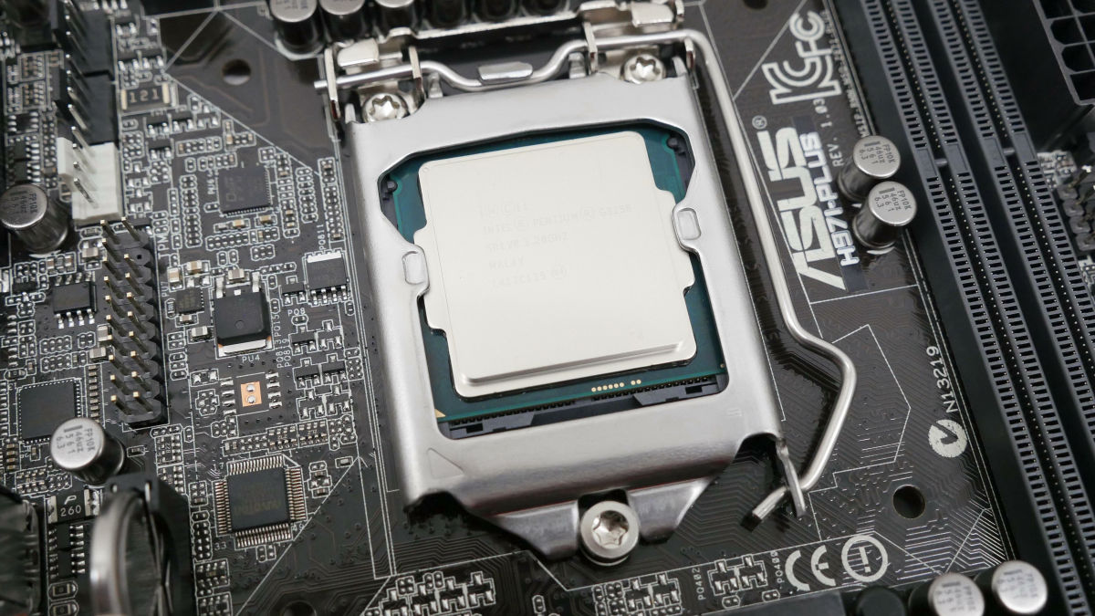
I was able to install the CPU. To prevent damage to the pins when changing the motherboard, it is important to keep the missing socket cover so as not to lose it.
Since the CPU generates heat, cool it with the CPU cooler. Intel genuine CPU cooler is a type that mounted a fan without a sleeve on an aluminum heat sink. The fans were made by DELTA.
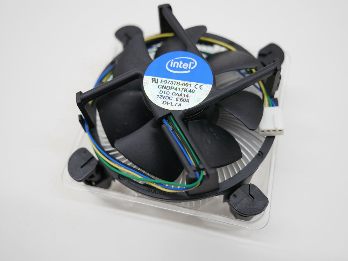
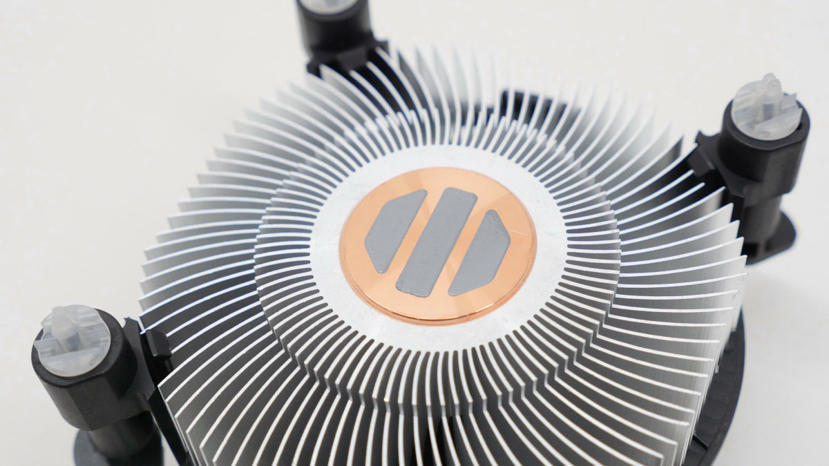
Gray grease has already been painted on the copper core on the back. Although this grease is solid, it melts and spreads when you start the PC for the first time so that it fits into the heat spreader.
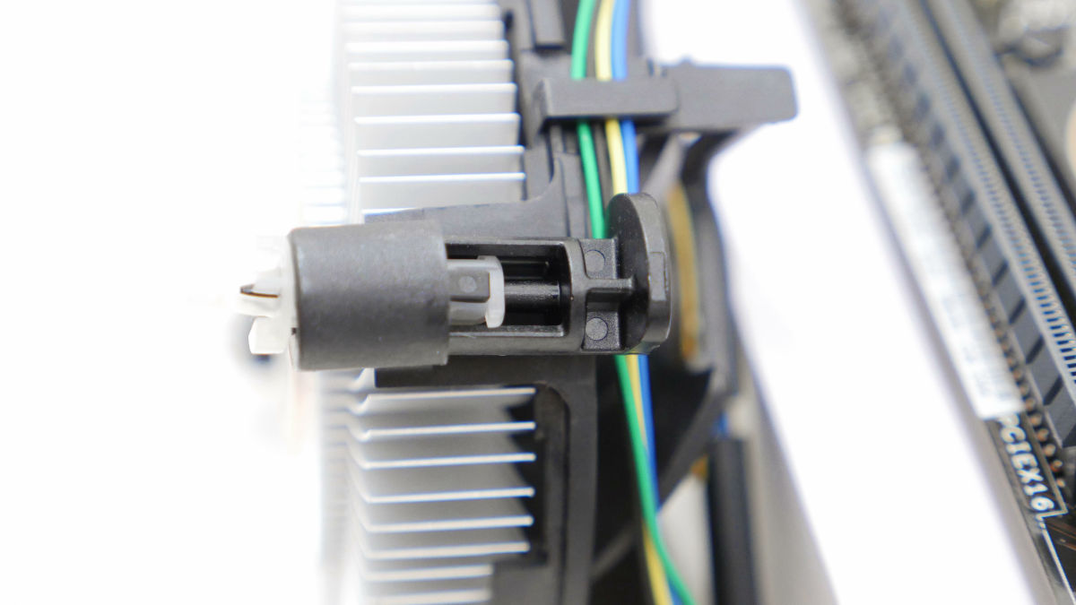
Intel genuine CPU cooler is a bush pin type. It is unpopular that it is difficult to understand how to remove it.
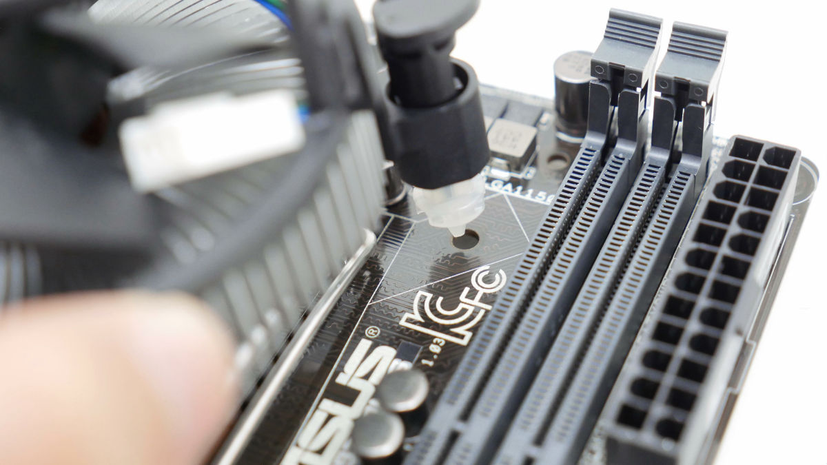
However, mounting itself is very easy. Firstly, insert the tip of the bushing pin into the hole at the four corners around the CPU socket.
Looking like this from the back of the motherboard.
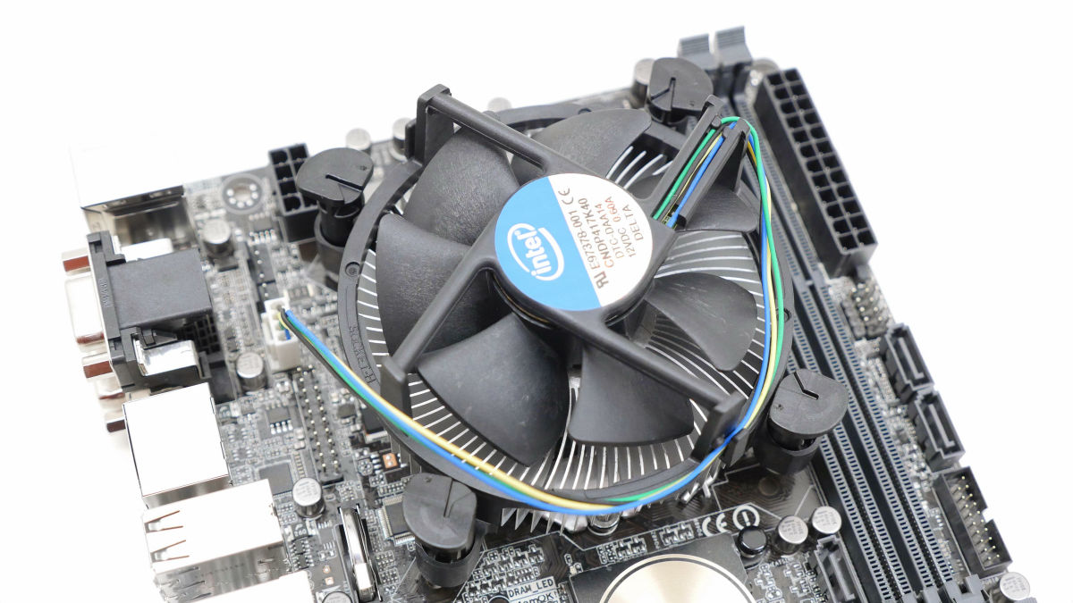
Also keeping the direction in advance so that the fan connector of the CPU cooler can be connected to the fan connector of the motherboard makes handling easier.
Next, when it is confirmed that the notch of the bush pin faces the direction of the fan, push in the bush pin. Push it until you hear "snap" sound OK.
From the back side, a black pin appears from the tip of the bush pin and can be fixed. Once all four corners are fastened, the CPU cooler has been installed.
◆ Basic Part 3: Memory
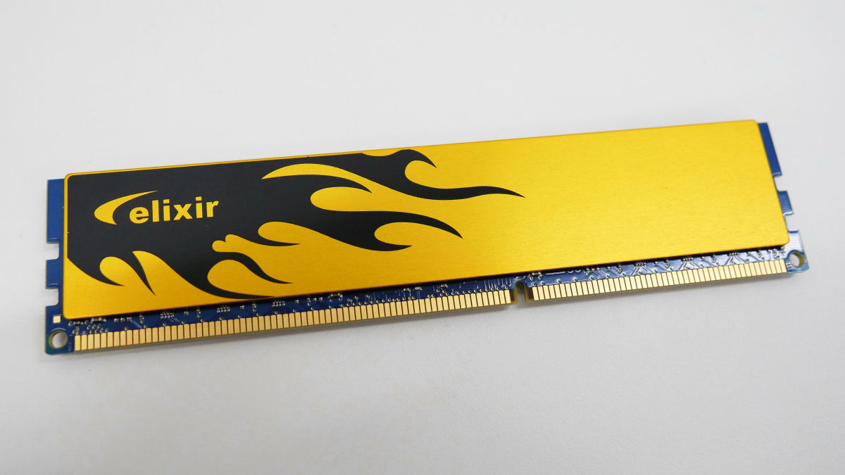
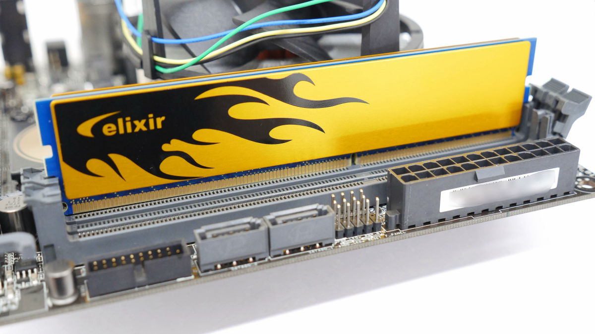
The H97I-PLUS supports DDR3 memory. This time, CFD ELIXIR's "W3U1600HQ-4G"use.
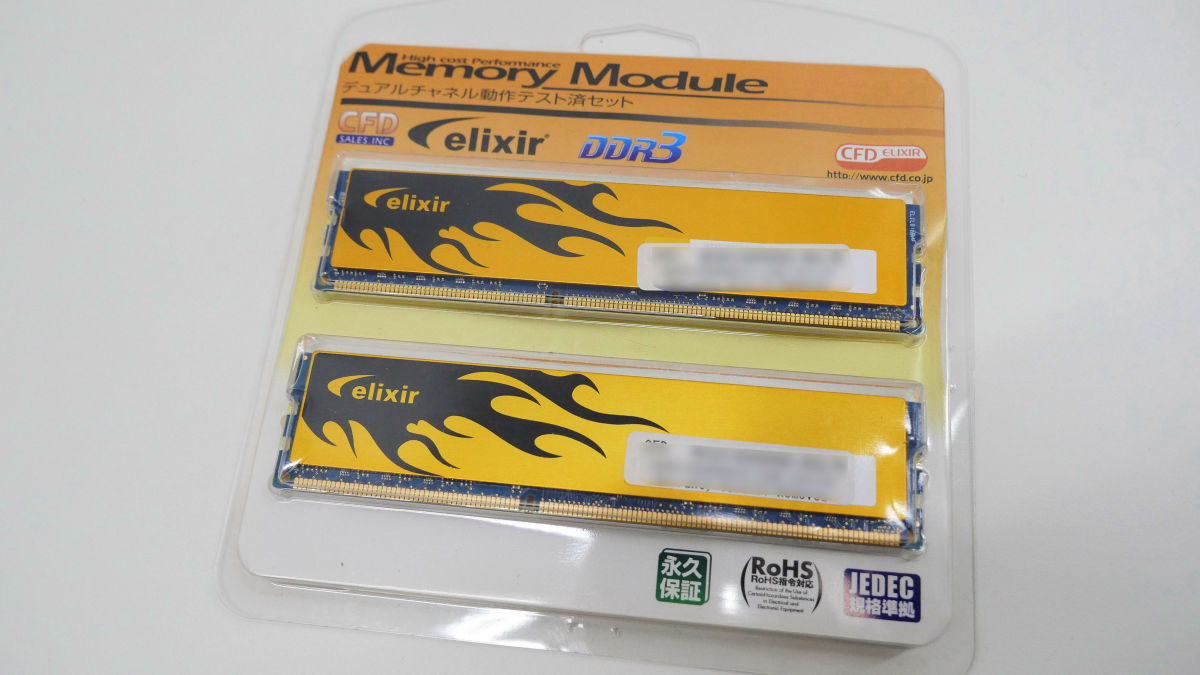
Because it uses two, it becomes 4GB × 2 = 8GB. The golden heat sink is super cool. I can not see it if I put it in a case, but maybe I should pay attention ....
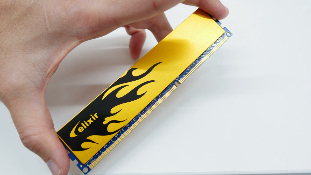
The point is to have the memory so as not to touch the gold contacts. Even having a heat sink is OK.
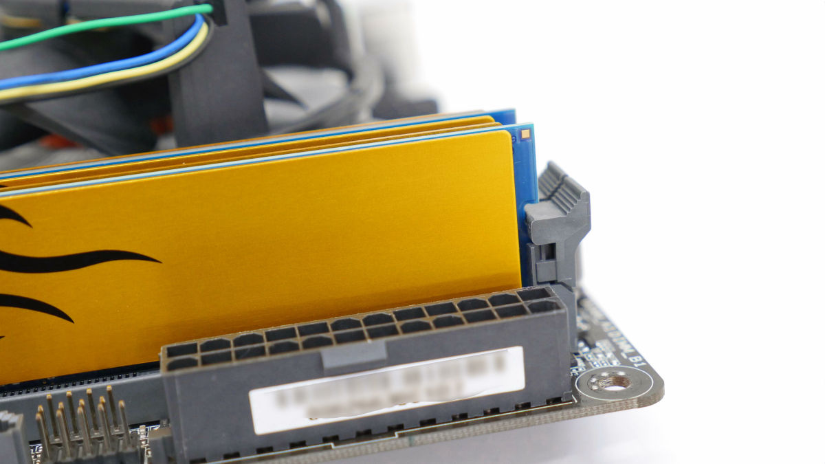
Release the memory slot lock outward. In addition, H97I - PLUS lock is only on one side. This is subtle because it is easier to remove the memory with locks on both sides ... ....

With the position of the notch (red frame) of the memory slot aligned, push it hard from the top OK.
It is a mechanism that the lock is fixed and returned to the inside naturally if it can be installed correctly.
◆ Basic Part 4: Power Supply
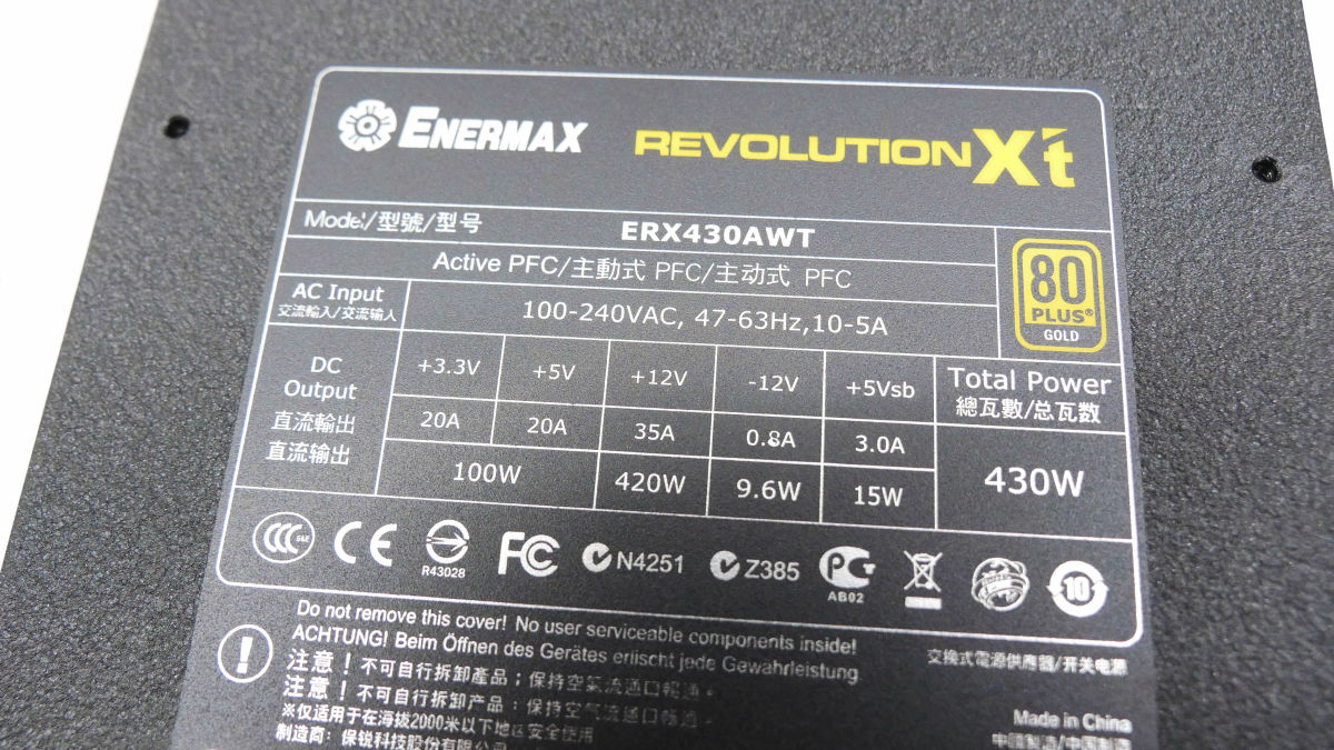
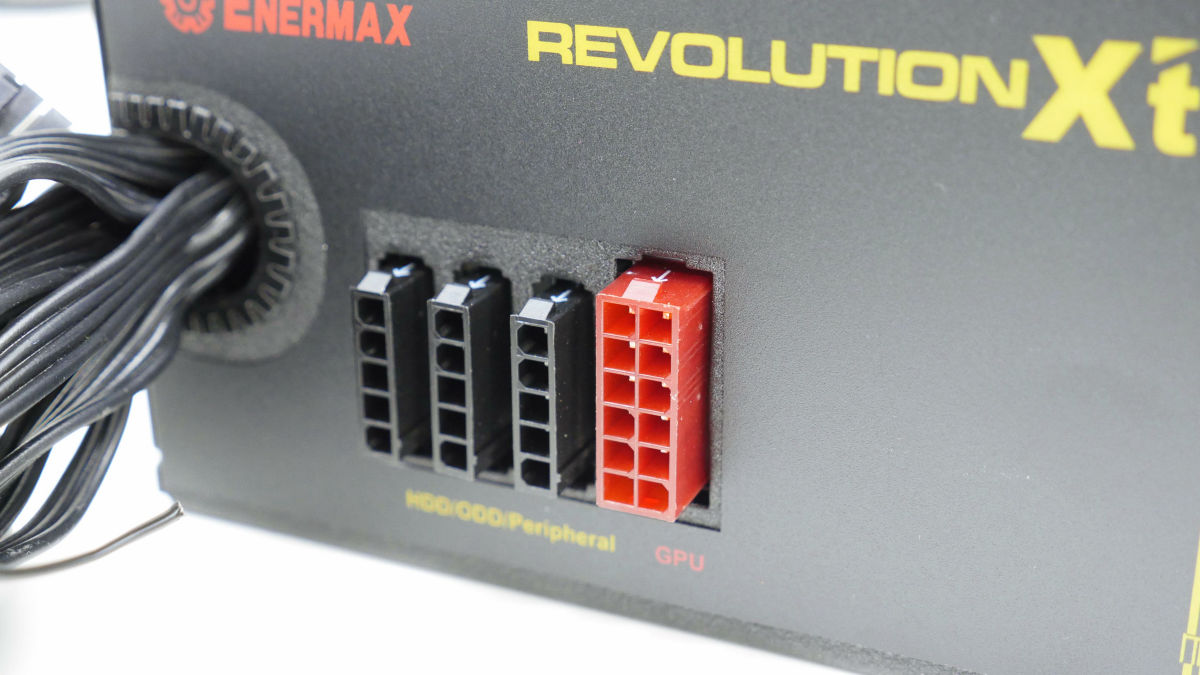
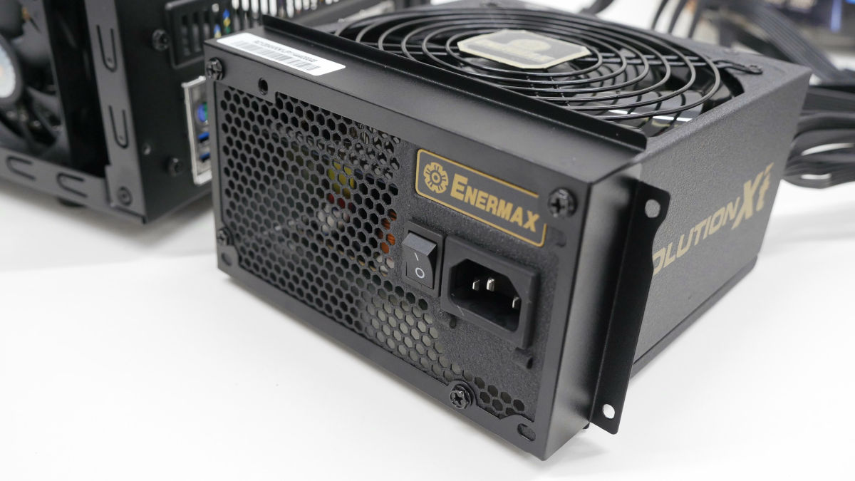
The fourth basic part is the "power supply" of the parts that supplies power to the PC. This time ENERMAX's "Revolution X't 430 W ERX 430 AWT"Is used.
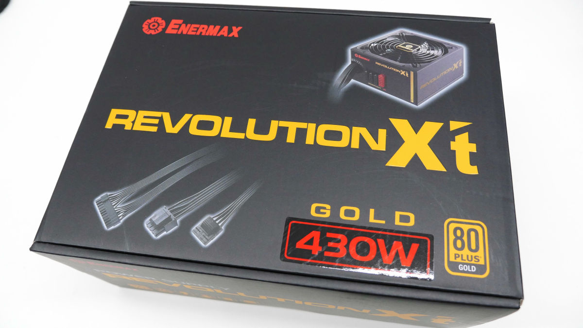
The inside of the box looks like this. Power supply main body and modular cable, power supply cable, instructions included.

"80 PLUS GOLD"Total 430 W specifications already acquired. As 12V is 1 lane (430 W), it seems to be compatible with CPU OC and high-end high-power graphic board.
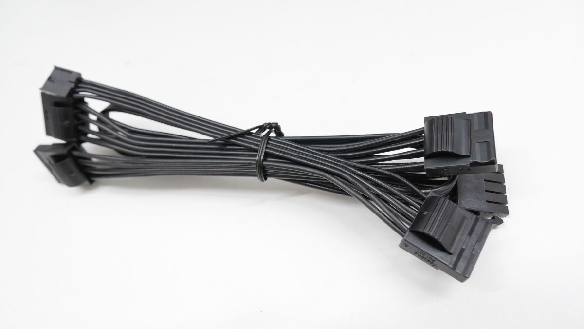
SATA power cable and peripheral power cable etc. are semi plug-in type to select individually and install them.
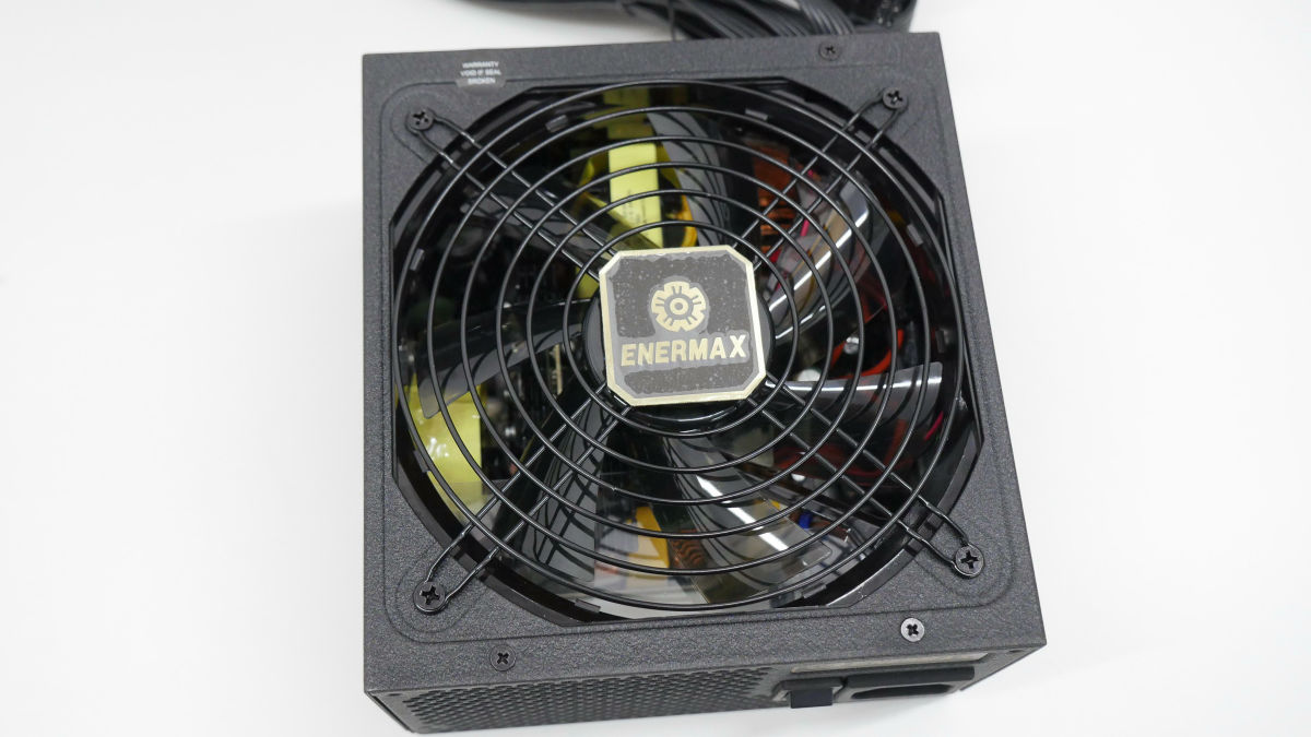
The cooling fan is 14 cm type.
◆ Start check in provisional state
Confirm startup when CPU / memory is mounted on the motherboard. It is very troublesome to remove it from the PC case again when trouble occurs that does not start after installing the motherboard or power supply to the PC case, so it is recommended to check the startup at this point.
(Note) This time we have a minimum configuration of 6 parts including PC case · storage so we do not have graphic board or optical drive.
Place the motherboard on the box and connect the power cable.
Also connect the auxiliary power cable for CPU. It also connects to the display.

Two pins surrounded by the red frame of the system panel connector are the pins for the power button. In other words, if you connect here, the system can turn on the power. So, if you connect the tip of a flathead screwdriver to these two pins ...

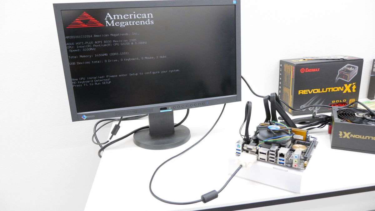
The fan of the CPU cooler rotated and succeeded in turning on the power.

Successfully, POST screen appeared, startup check was successful. If you do not start up at this point, either because it is incorrectly assembled or there is a problem with the PC part, you need to find the cause. When checking in such exposed state, because it is easy to find the problem part, it is recommended to check the activation at the temporary assembly stage before incorporating it in the PC case.
◆ Basic Part 5: PC Case
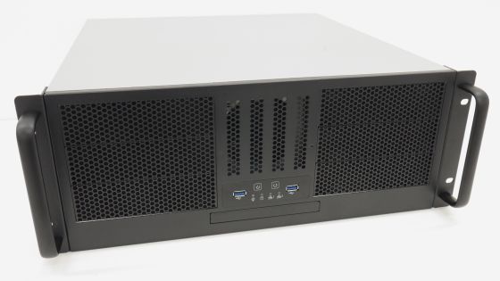
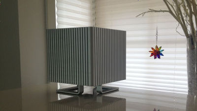
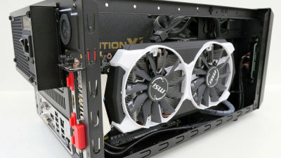
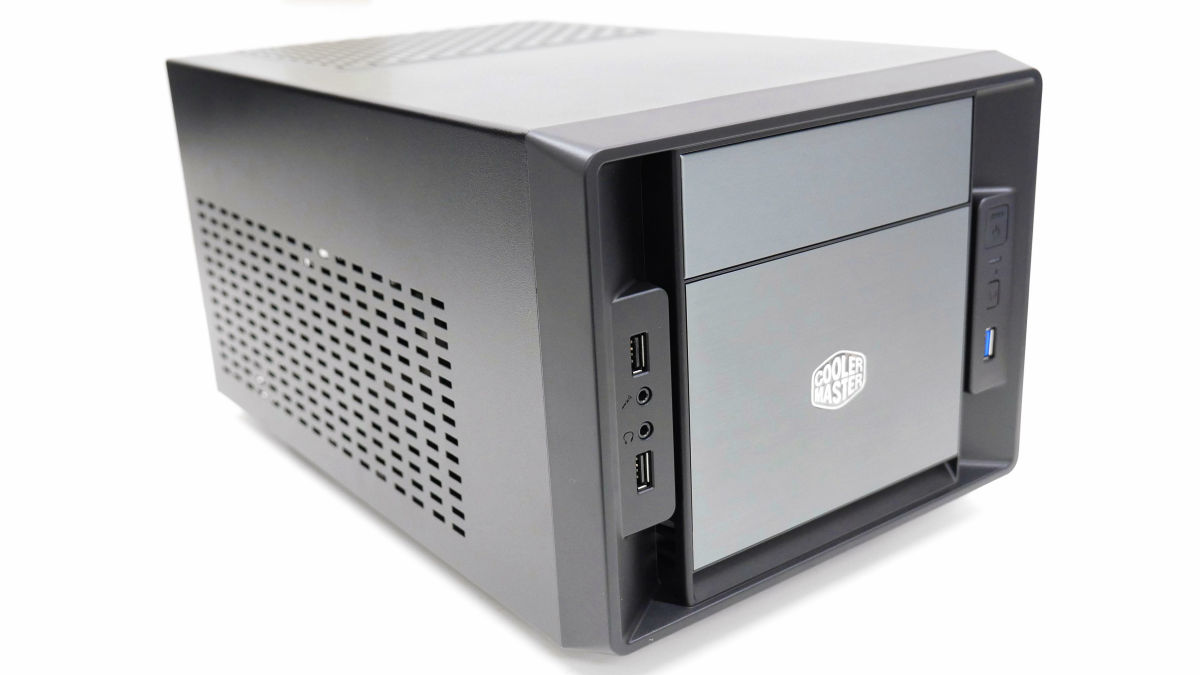
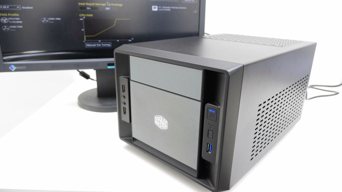
Being able to use a case of my favorite design is a big advantage of my own PC. This time Cooler Master's "Elite 120 CubeI will try to make a small PC. Although it is compact, full-size graphic board can be inserted, so it is also possible to make gaming PC.
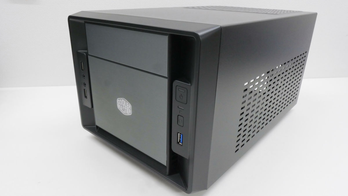
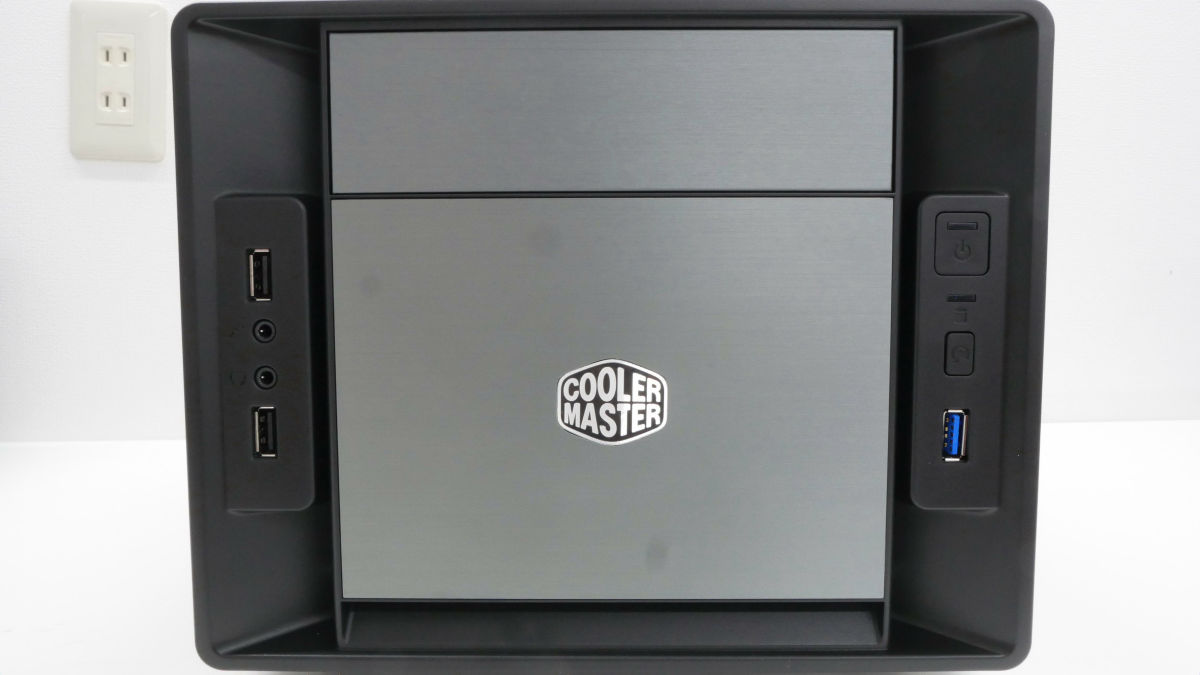
5 inch bay at the top center. DVD or Blu-Ray optical drive can be installed. USB2.0 port on the left, power button on the right, reset button, USB 3.0 port.
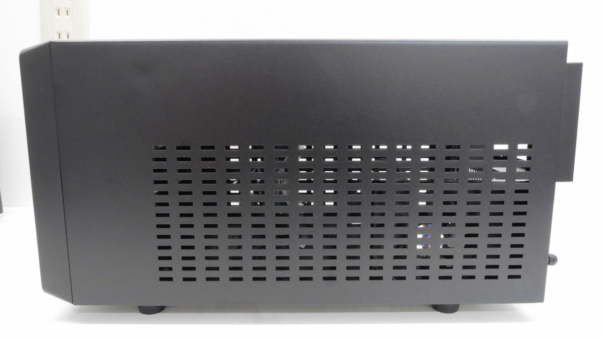
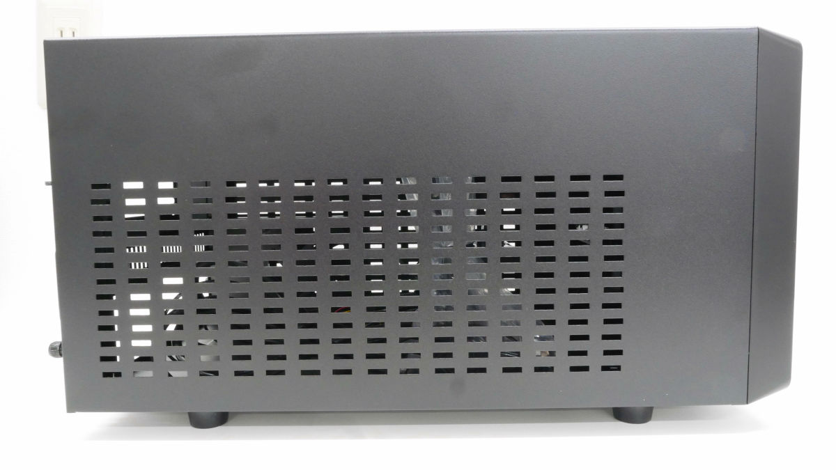
Left side is slit for supply / exhaust.
The back is like this. Power is supplied to the part of the hole which is opened up and the back plate of the motherboard is fitted to the part of the hole underneath.
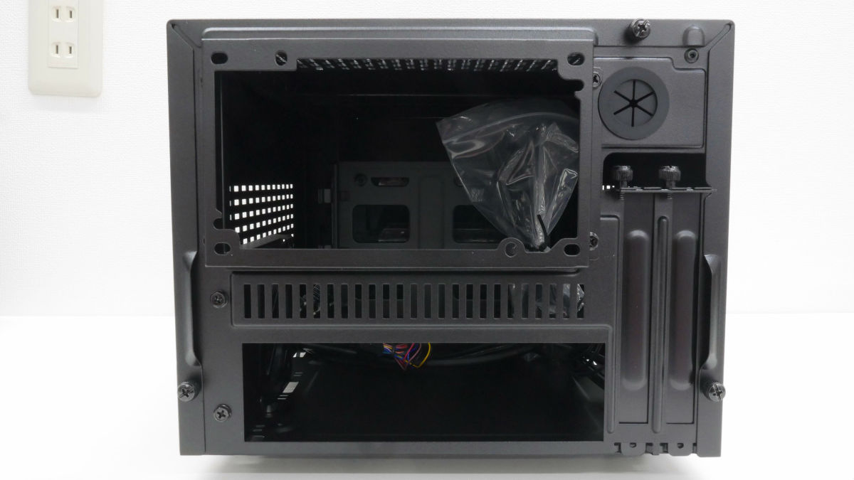
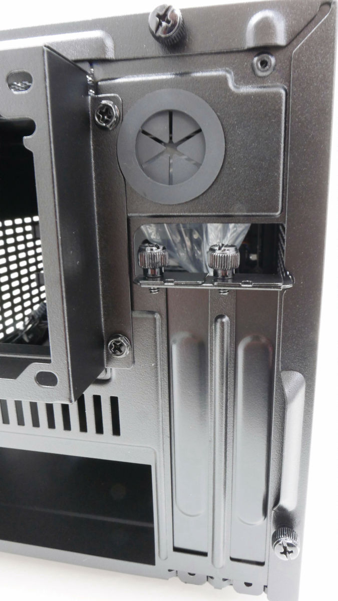
On the right side there is also a hole for water hose removal hose and expansion slot.
The bottom is like this. The screw at the upper right of the photo is for fixing the holder of the fan.
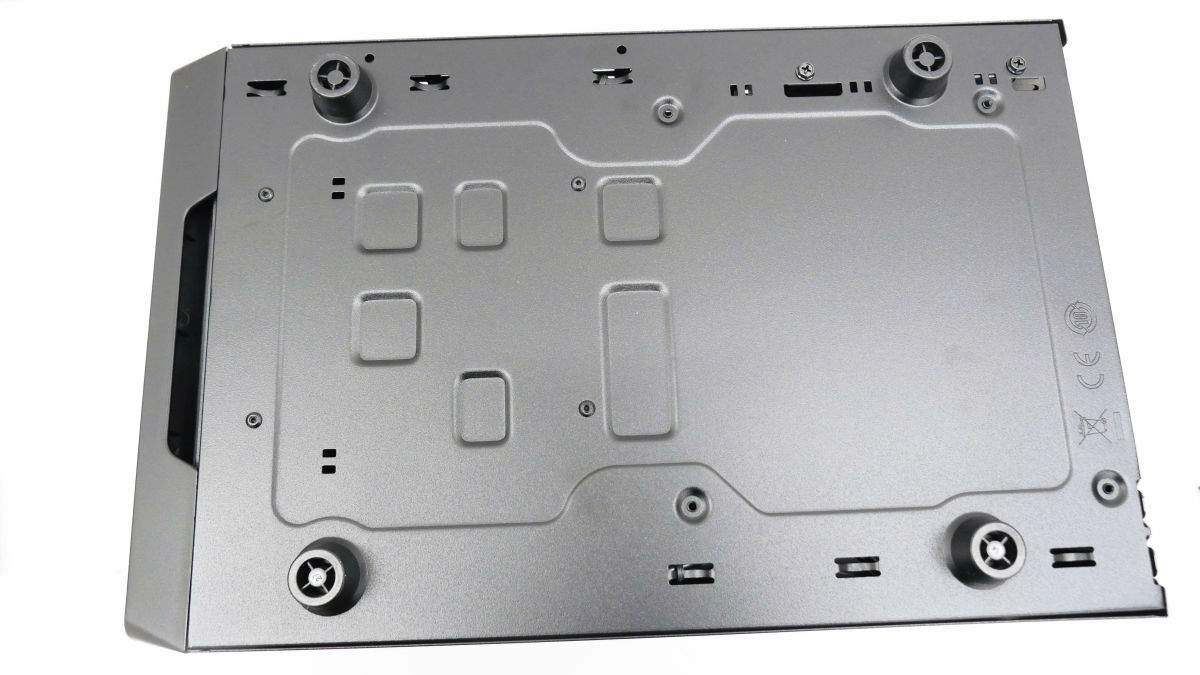
The right side is the slit which corresponds to the air intake when carrying the graphic board.
If you remove the three thumbscrews on the back ... ...
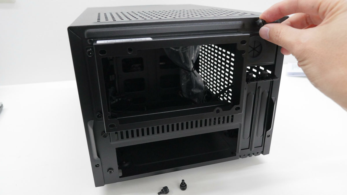
You can remove the cover in the shape of a U by pulling it out in the backward direction.

Inside is like this. Please remove the plastic bag because it contains accessories such as screws and tie wraps.

5 inch bay space. If you place an optical drive, install it here.
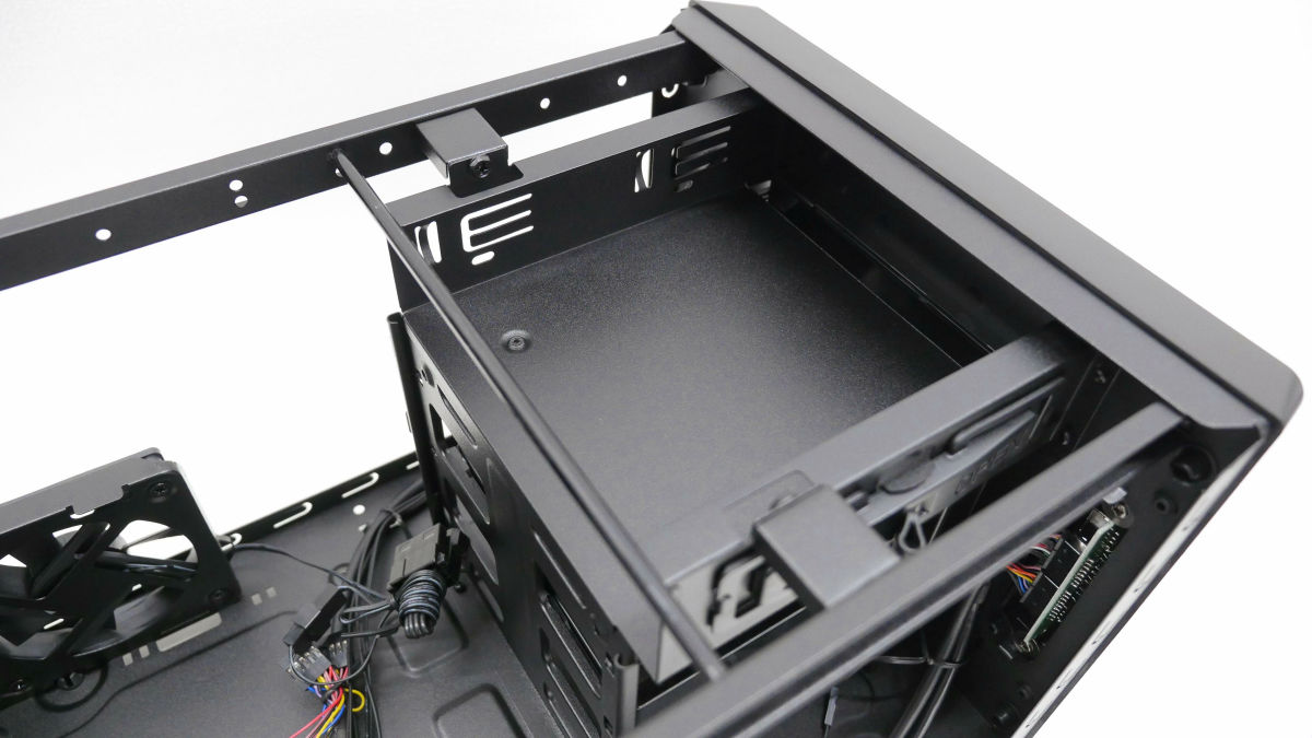
Below 5 inches bay is 3.5 inches bay. Drives such as HDD (hard disk) and SSD are installed here.
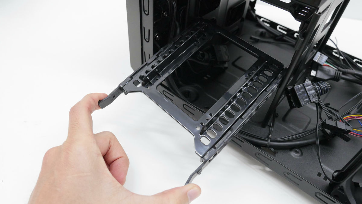
3.5 inch bay holder can be removed without tools.
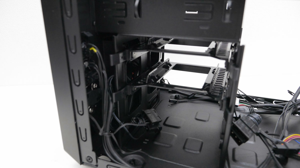
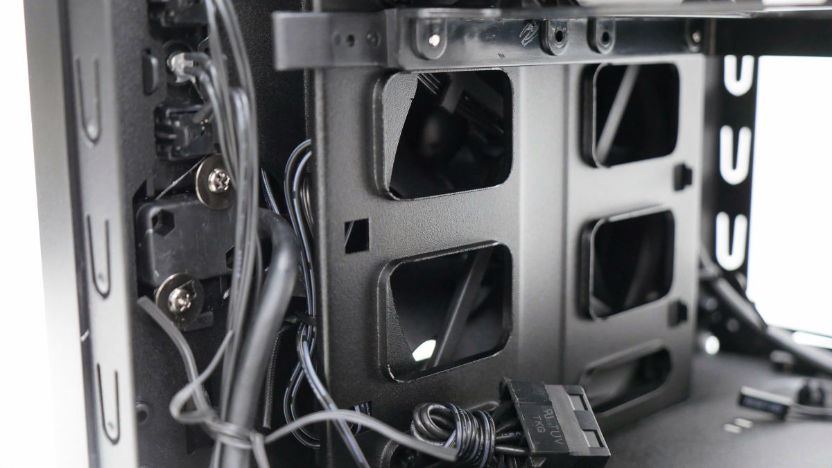
3.5 inch bay A partition plate that can mount a 12 cm fan behind. In addition, a 12 cm fan for suction is already installed in the back of the partition plate.
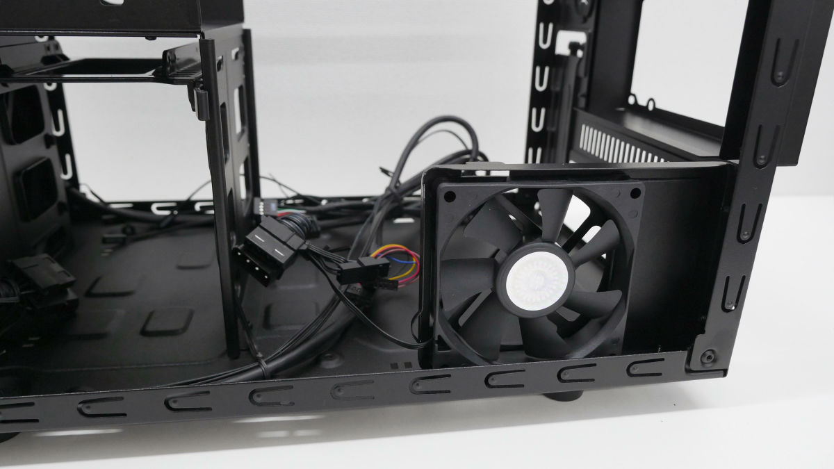
8 cm fan on the left side. In the default condition, the fans were installed in the direction of the air intake.
◆ incorporate various parts into the case
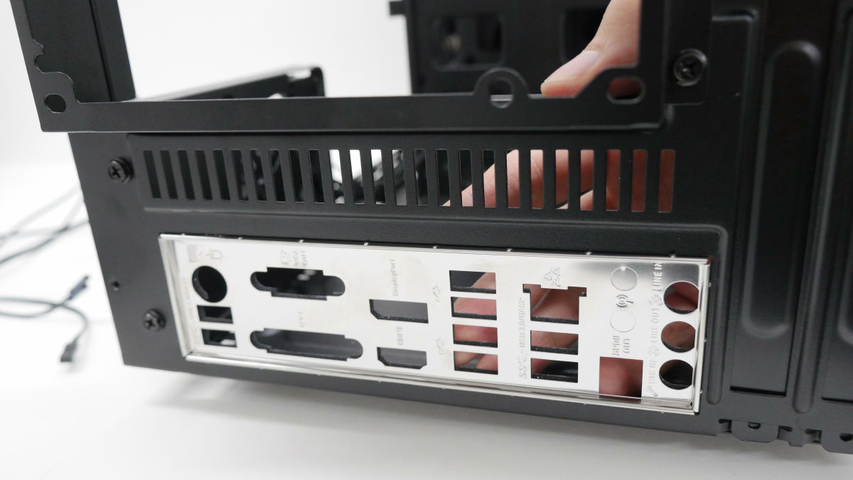
Finally, we will install the parts in the PC case. First of allThe first thing you need to do is "Install the back panel of the motherboard" task. If you forget this work, you will definitely forget to forget that you will be redone from scratch.
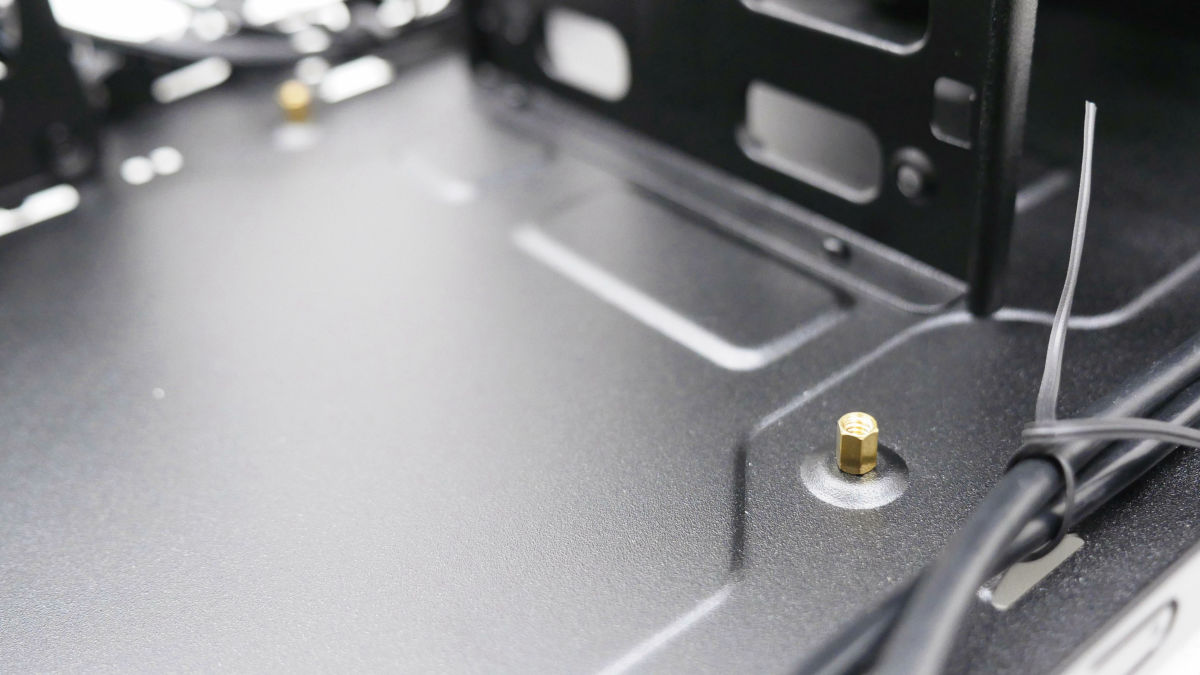
Next attach the spacers that fix the motherboard to four places.
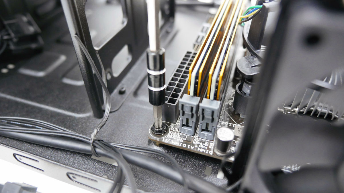
Fix the motherboard in four places along the spacer with an inch screw.
After installing the motherboard, do various wiring work. All power supply button, reset button, system lamp, system panel connector for HDD lamp are installed. Pin placement is described in the motherboard instruction manual.

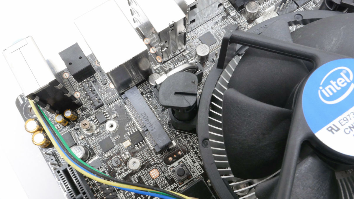
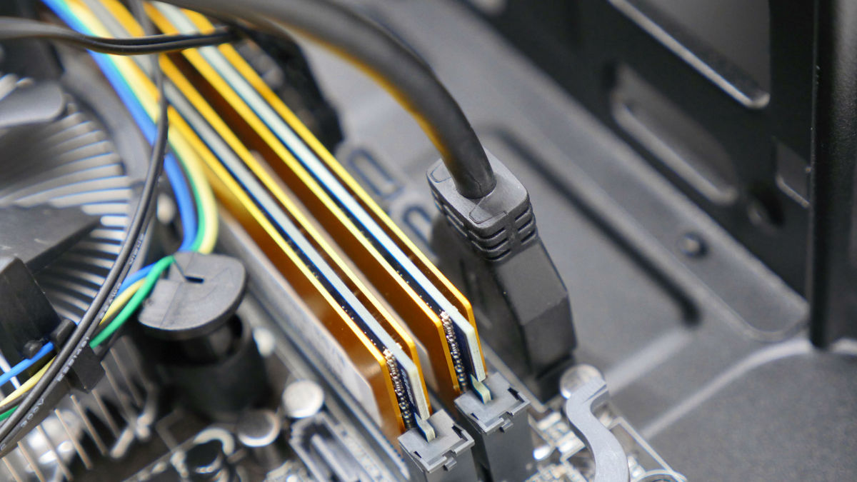
This is the USB 3.0 cable on the front of the PC case.
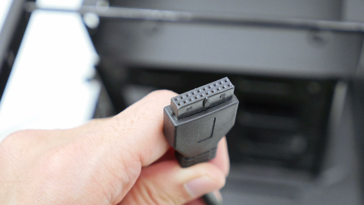
Insert in the connector mouth next to the memory.
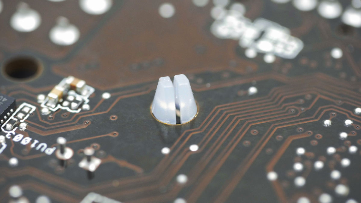
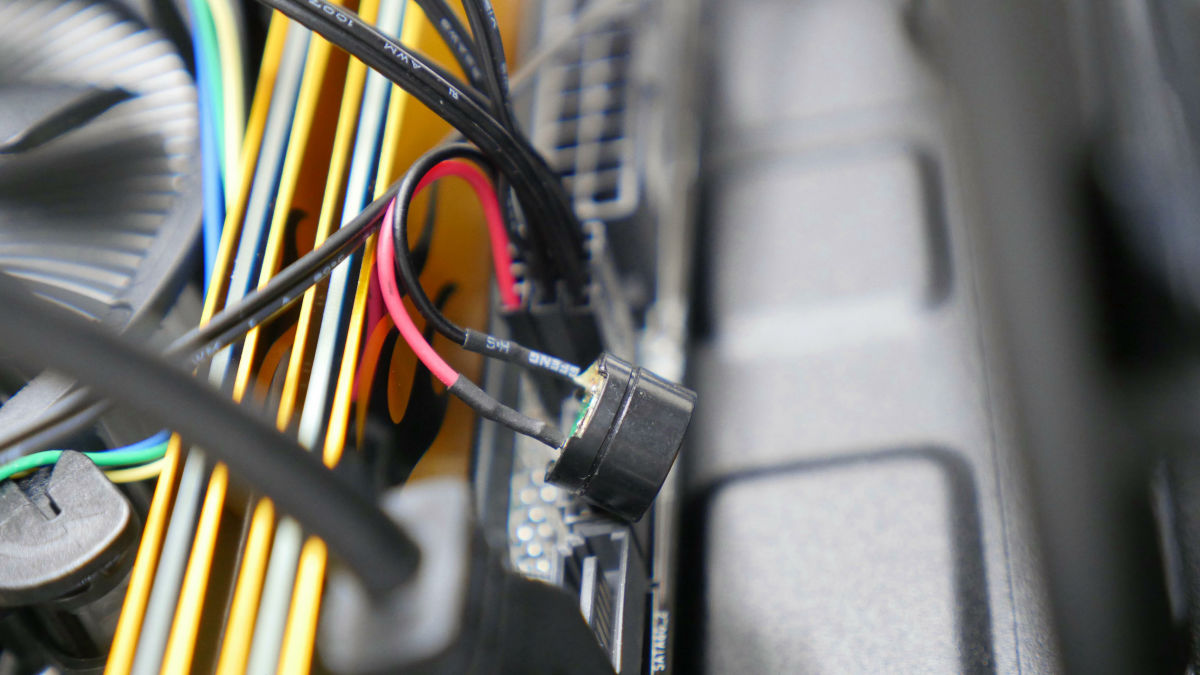
This is a speaker that beeps. It is called "Pi" which sounds when the PC starts up.
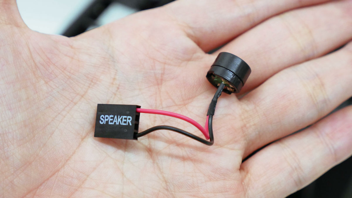
Whether or not to install depends entirely on taste. This time it installed. This pin arrangement is also described in the motherboard instruction manual.
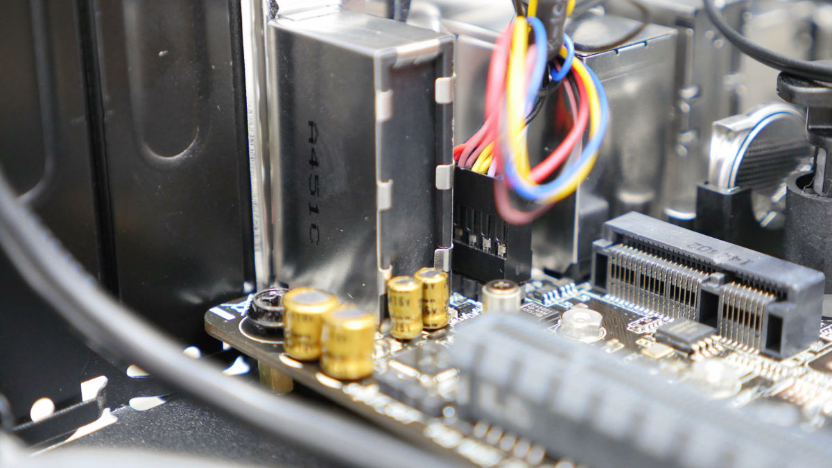
Audio connectors ......
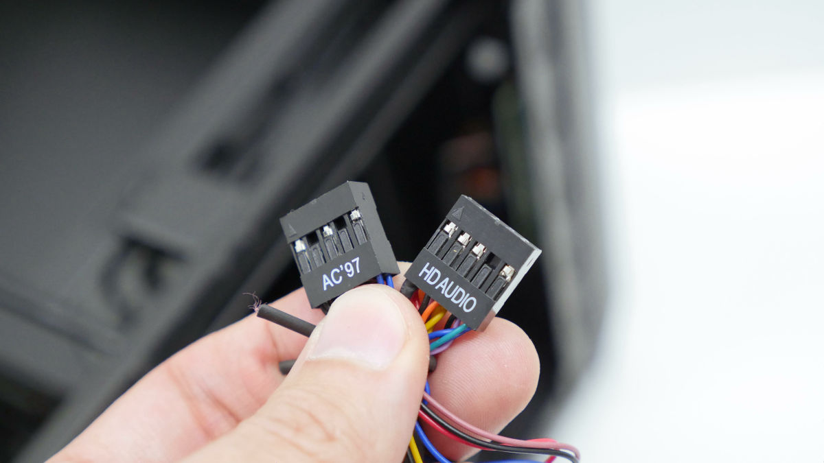
Installed in the clearance of the I / O port.
USB 2.0 connector on the front of the PC case ......
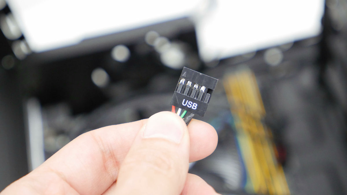
Attached to the pin next to PCI - Express.
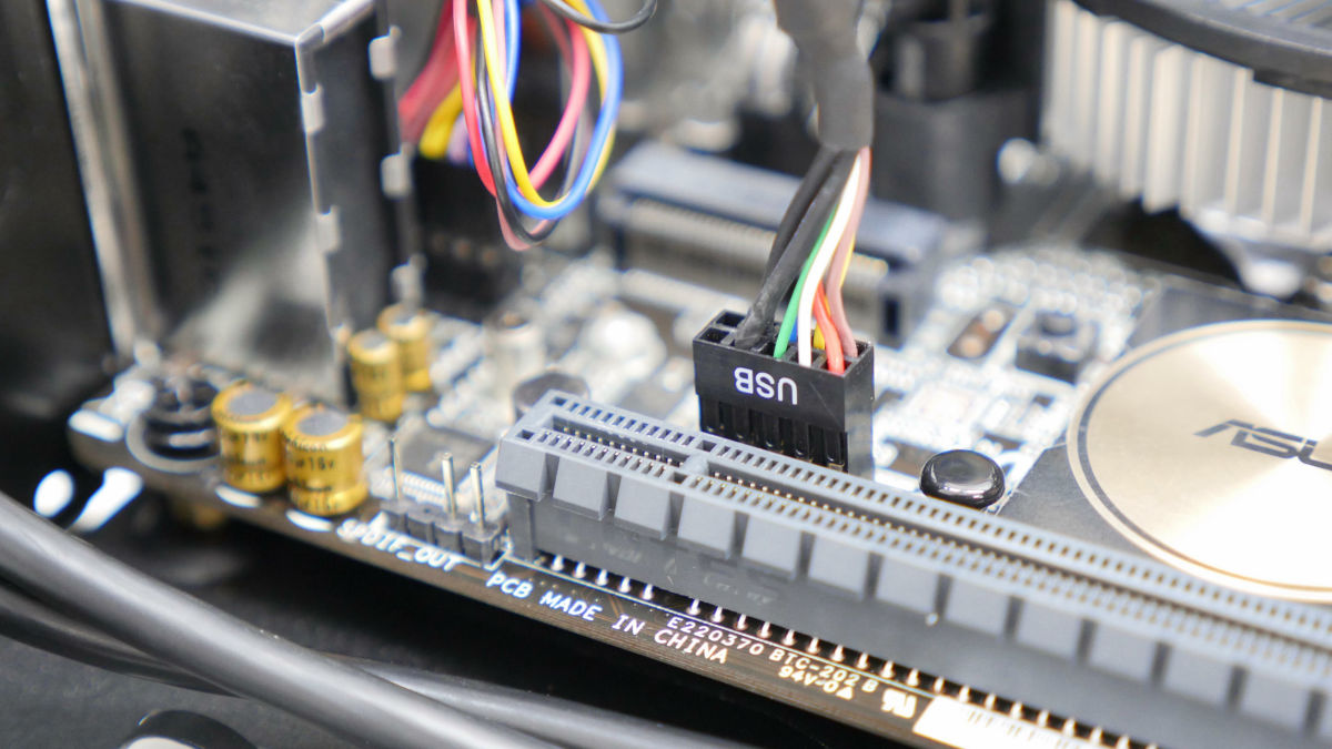
Fig. The cable is cluttered, but I will handle it later.
◆ Basic Part 6: Storage
Storage of data such as systems and files is storage. Storage for the system is roughly divided into two types, HDD and SSD. For a system I'd like to use SSDs that I'd love to use because I can make a comfortable environment crisp. This time Toshiba's "CSSD-S6T128NHG6Q(128 GB) "is used.

Contents are SSD and 3.5 inch conversion mounter.
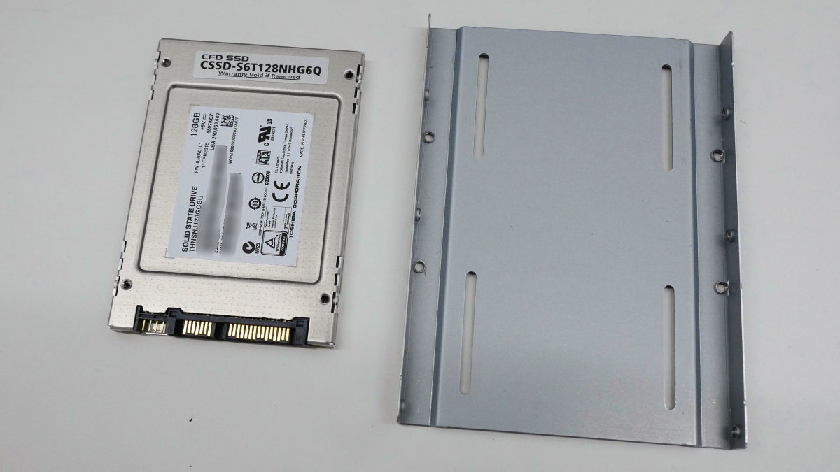
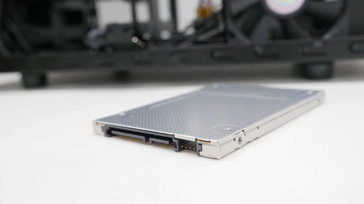
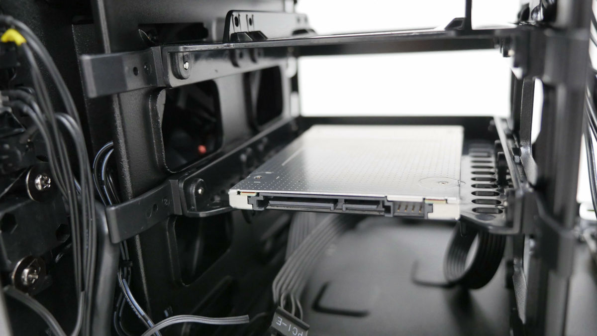
The SSD is 2.5 inches in size and 7 mm thick. The form factor isSATA 3.
Attach the SSD to the 3.5 inch bay holder of the PC case Elite 120 Cube.

It is OK if you fix 4 places with millimeter screw attached to the case from the back.
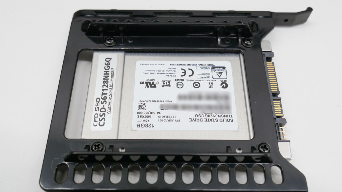
The installation work of the SSD is completed like this.

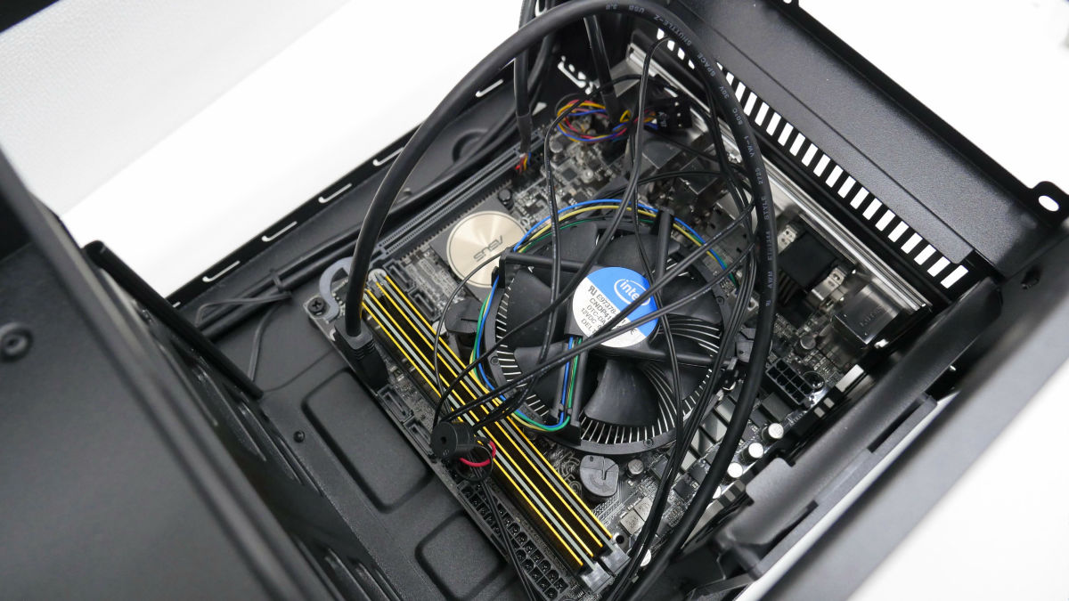
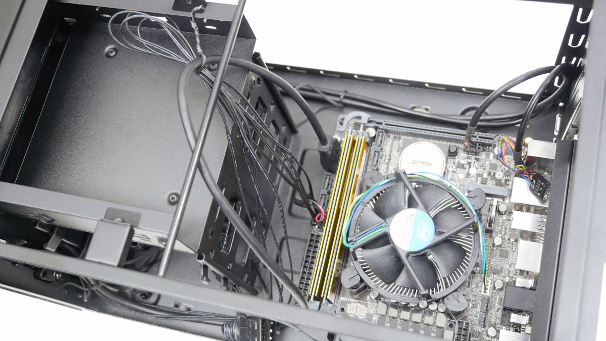
Next is power supply installation work. Before that, pull the cables together into the 5-inch bay section to make the top of the motherboard clearer.
Remove the 4 inch screws behind the case and take out the power holder ......
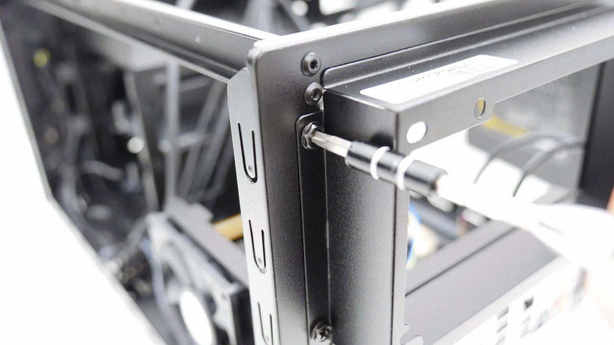
Fix the power supply holder to the power supply using the removed inch screw.
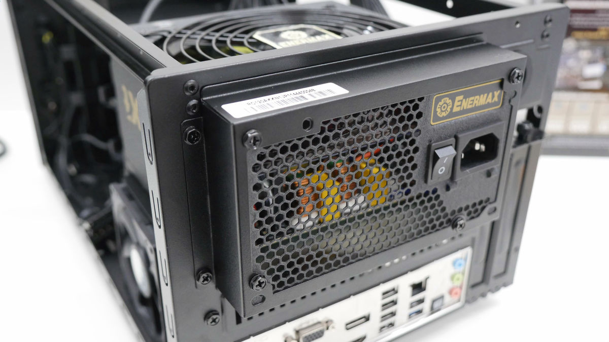
Fit the power supply and fix it to the PC case with the inch screw attached to the PC case. This time it was mounted so that the 14 cm fan of the power supply faced upward.
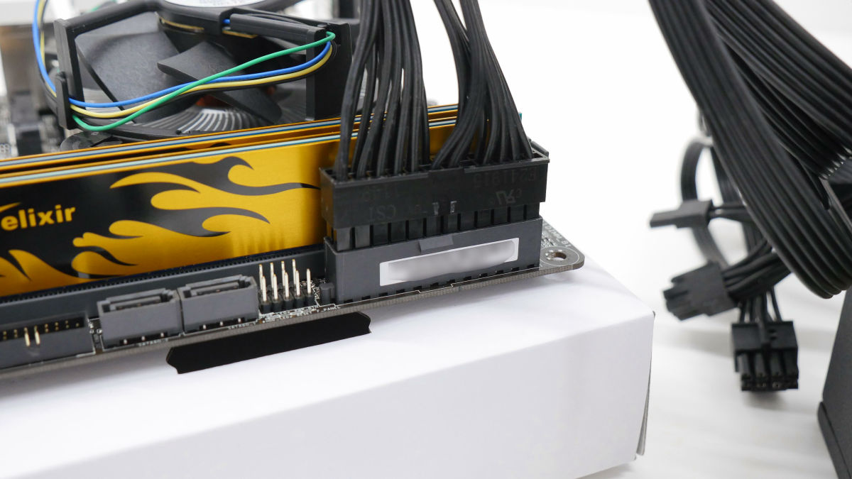
First insert the power cable (24 pin) into the motherboard.

It is necessary to remove the fan to connect the auxiliary power cable for the CPU. Two inch screws behind the PC case ......
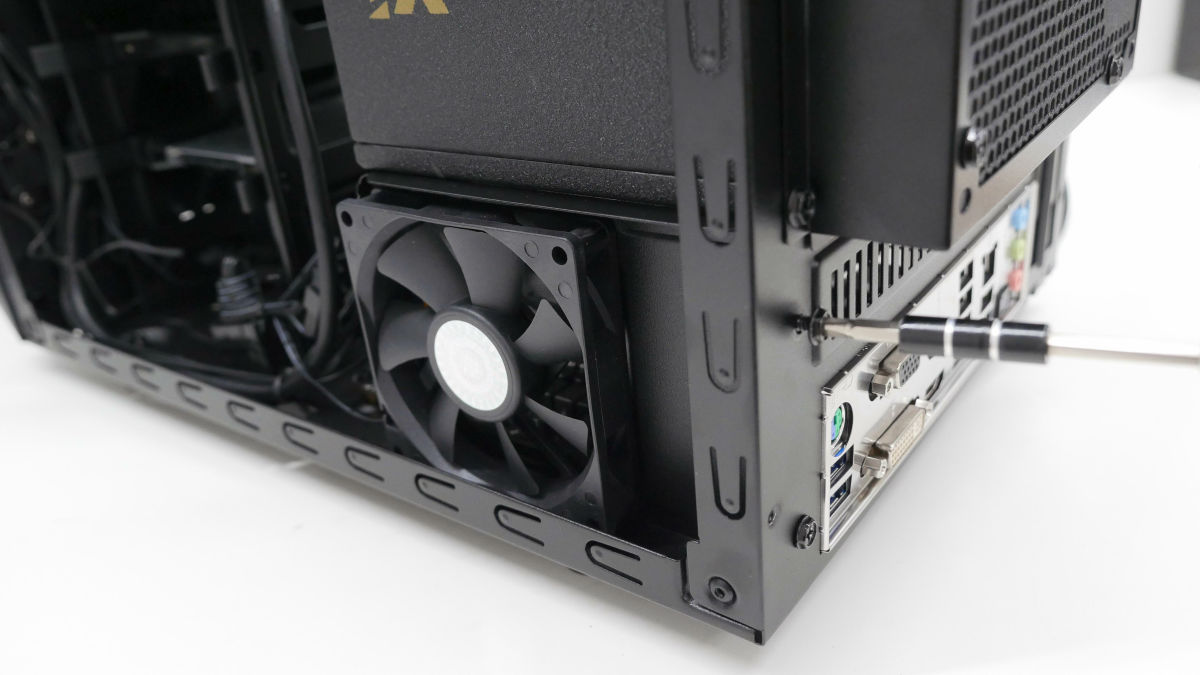
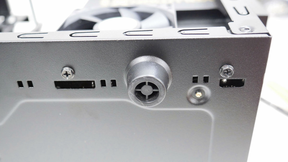
If you remove the two inch screws on the bottom of the PC case, you can remove the holder with the 8 cm fan.
This made it easy to connect the auxiliary power cable for the CPU.

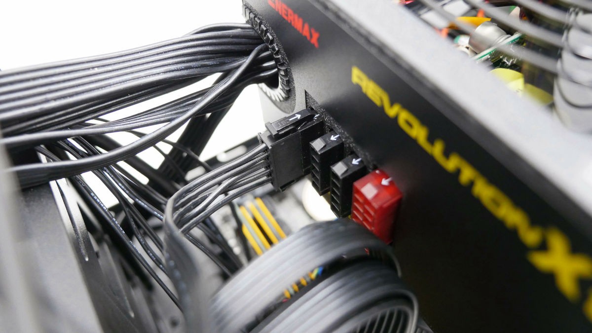
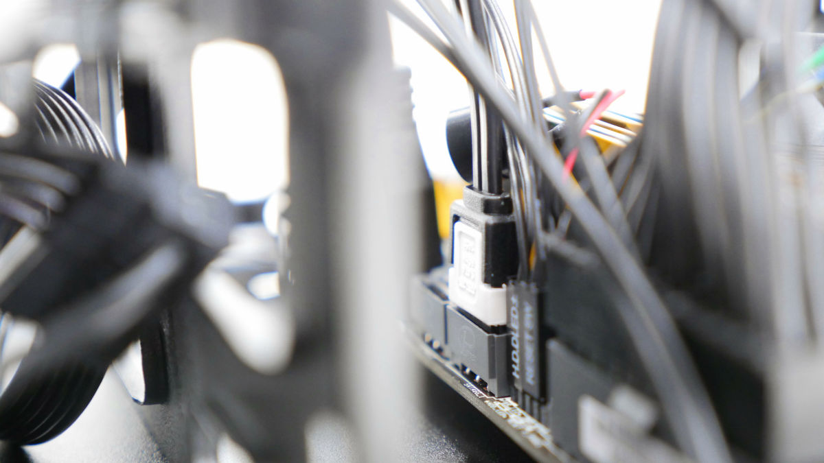
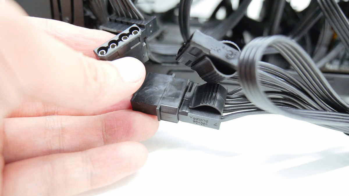
Next, attach the power cable for SATA that was attached to the power supply.
This connector ......
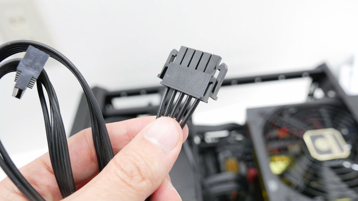
Insert the power supply so that the arrow can be seen.
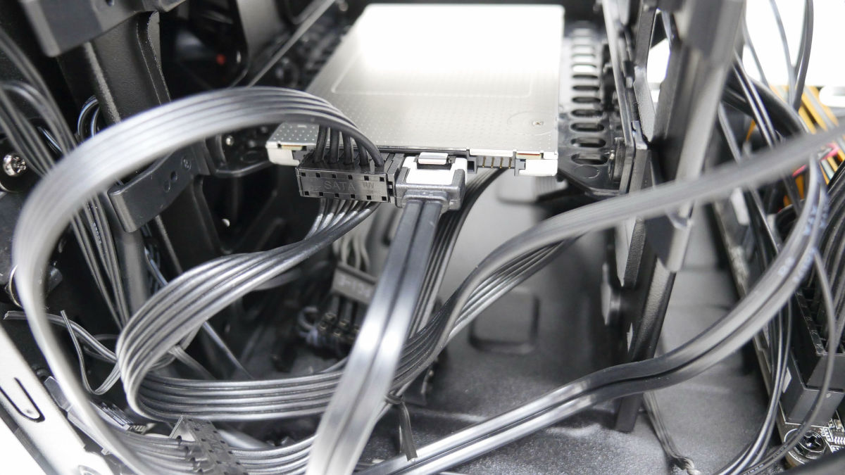
Power supply connector (female) ......
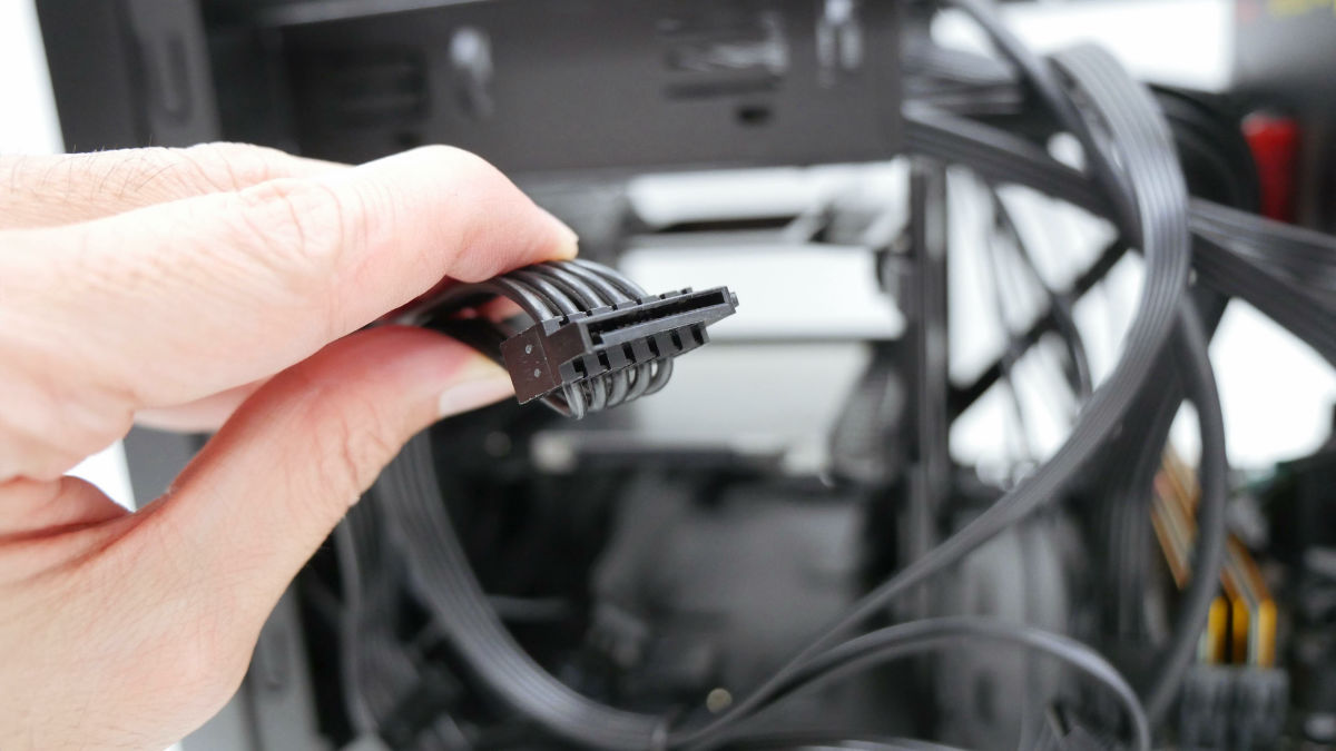
Attach it to the power connector (male) of the SSD. Be careful of the direction as it is L-shaped.
This is the insertion completion.
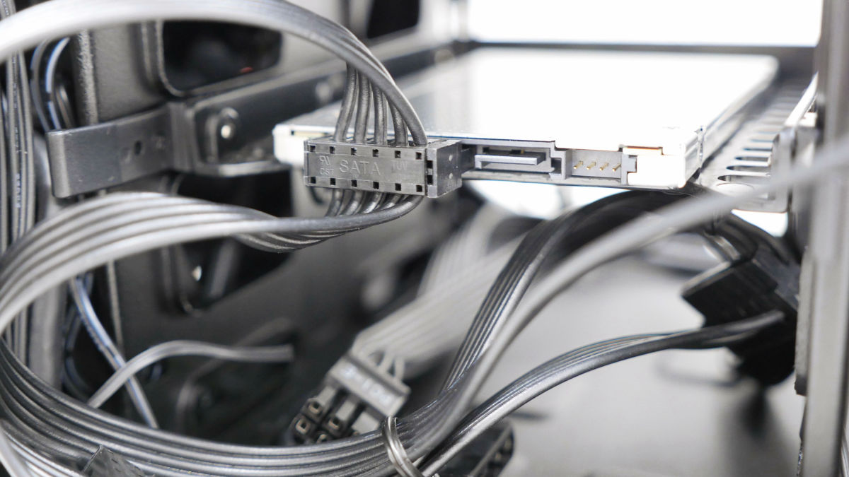
Next, take out the SATA cable attached to the motherboard ... ...
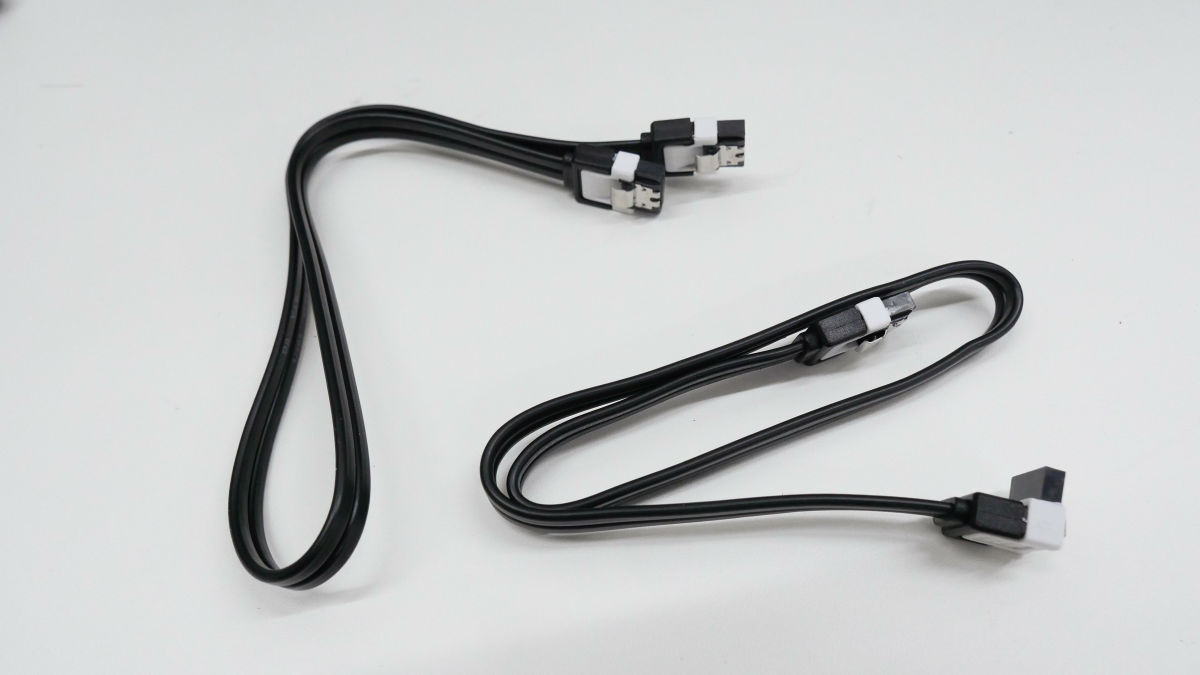
Attached to the SATA connector of the motherboard.
If you attach the other to the SSD, the connection between the SSD and the motherboard is completed.
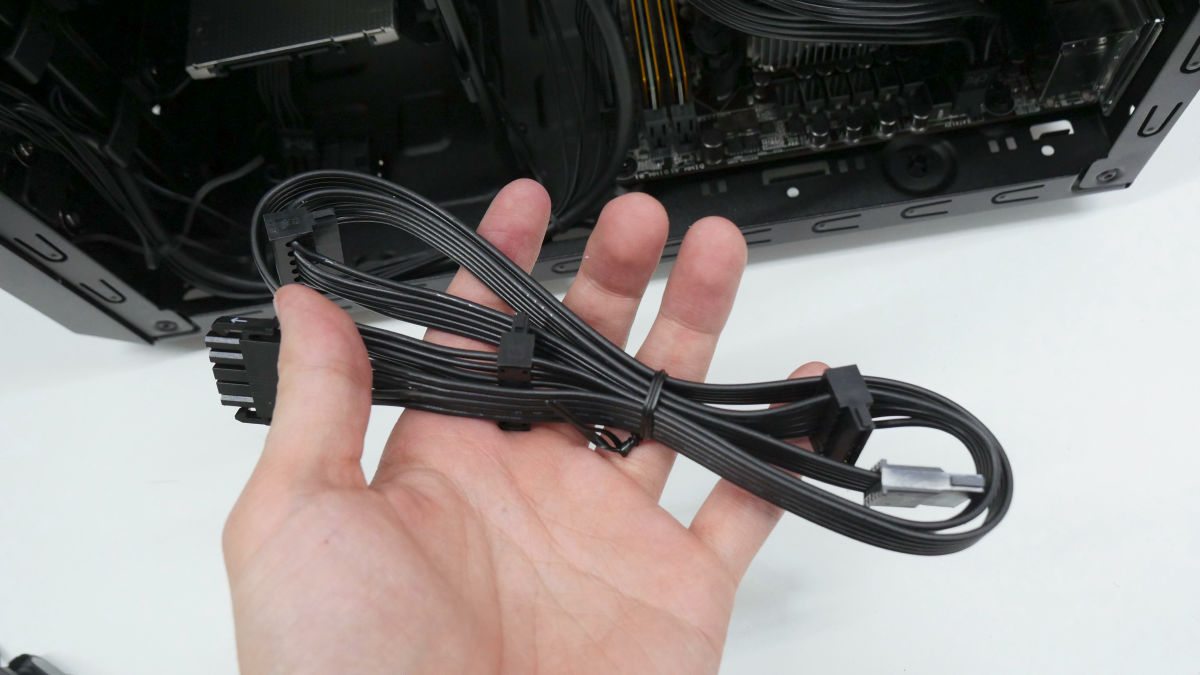
Finally install the power cable for the fan. Attach the peripheral type cable to the power supply modular.
Connect with the front 12 cm fan peripheral connector.
If you also connect the rear 8cm fan connector, all wiring is completed.

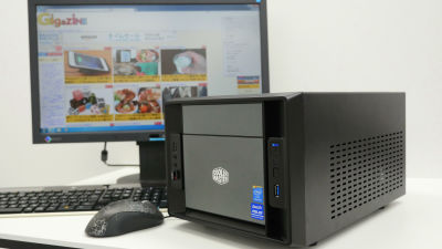
Finally, if you install a U-shaped cover, you can complete your own personal computer.
If you have one driver + PC you can make it with a feeling of plastic model. This is the end of how to make your own PC (hardware version). After that, complete the software setting such as installation of Windows 7 as your own PC software version, and complete "life" on your own PC.
· Continued
Guide for easy creation of original PC even for beginners 【Software installation】 - GIGAZINE
Related Posts: