Arduino module kit "ARDUINO CODING KIT" appeared in modular electronic circuit "little Bits" so I tried programming experience
The electronic circuit can be assembled by sticking the module snappy with a magnet "Little Bits (Little Bitz)", The microcomputer board"ArduinoModule has appeared. We did not need any breadboards, soldering or troublesome wiring, so we could assemble electronic circuits and experience Arduino programming, so we immediately assembled the circuit and programmed it.
ARDUINO CODING KIT product information - littleBits
http://jp.littlebits.com/kits/arduino-coding-kit/
◆ opening & exterior check
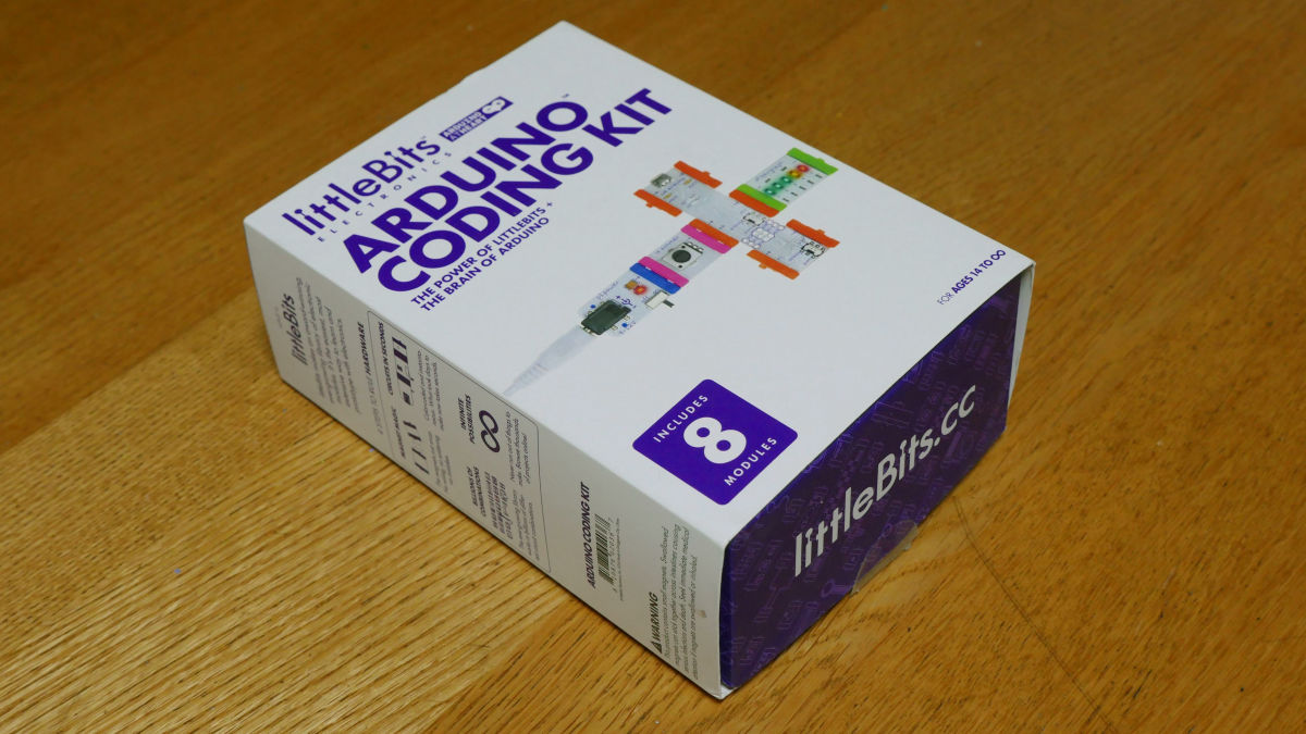
This is "ARDUINO CODING KIT". "The world of little Bits" "Arduino world" collaborated products.
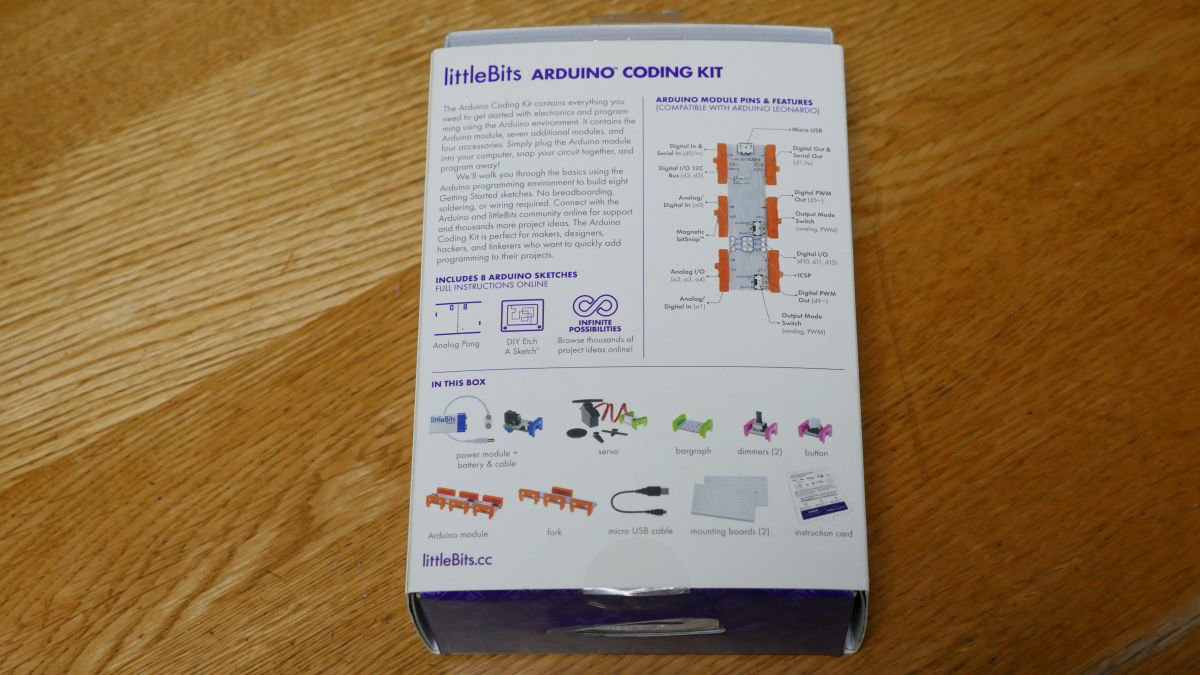
A brief description on the back. Breadboard, soldering, wiring etc are all unnecessary.
Slide the box and check the contents ......
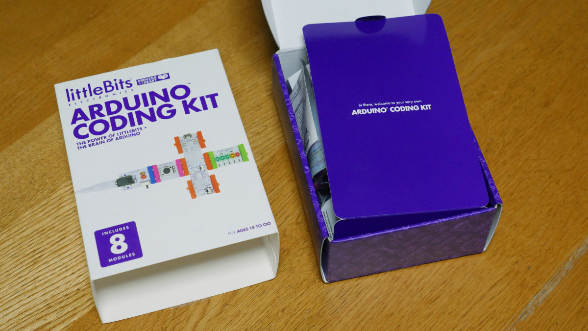
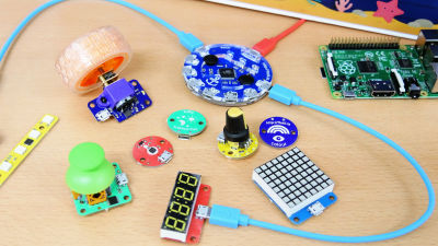
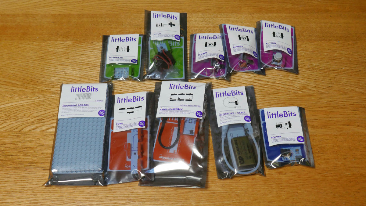
Many modules were packed up.

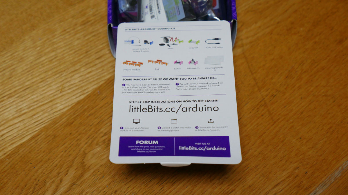
On the backside of something like a medium pig, the URL for Arduino's online manual is stated.
From the left, "bargraph", "servo", "dimmer" × 2, "button" from the top. The lower row shows "mounting board", "fork", "Arduino module", "battery & cable", "power" from the left.
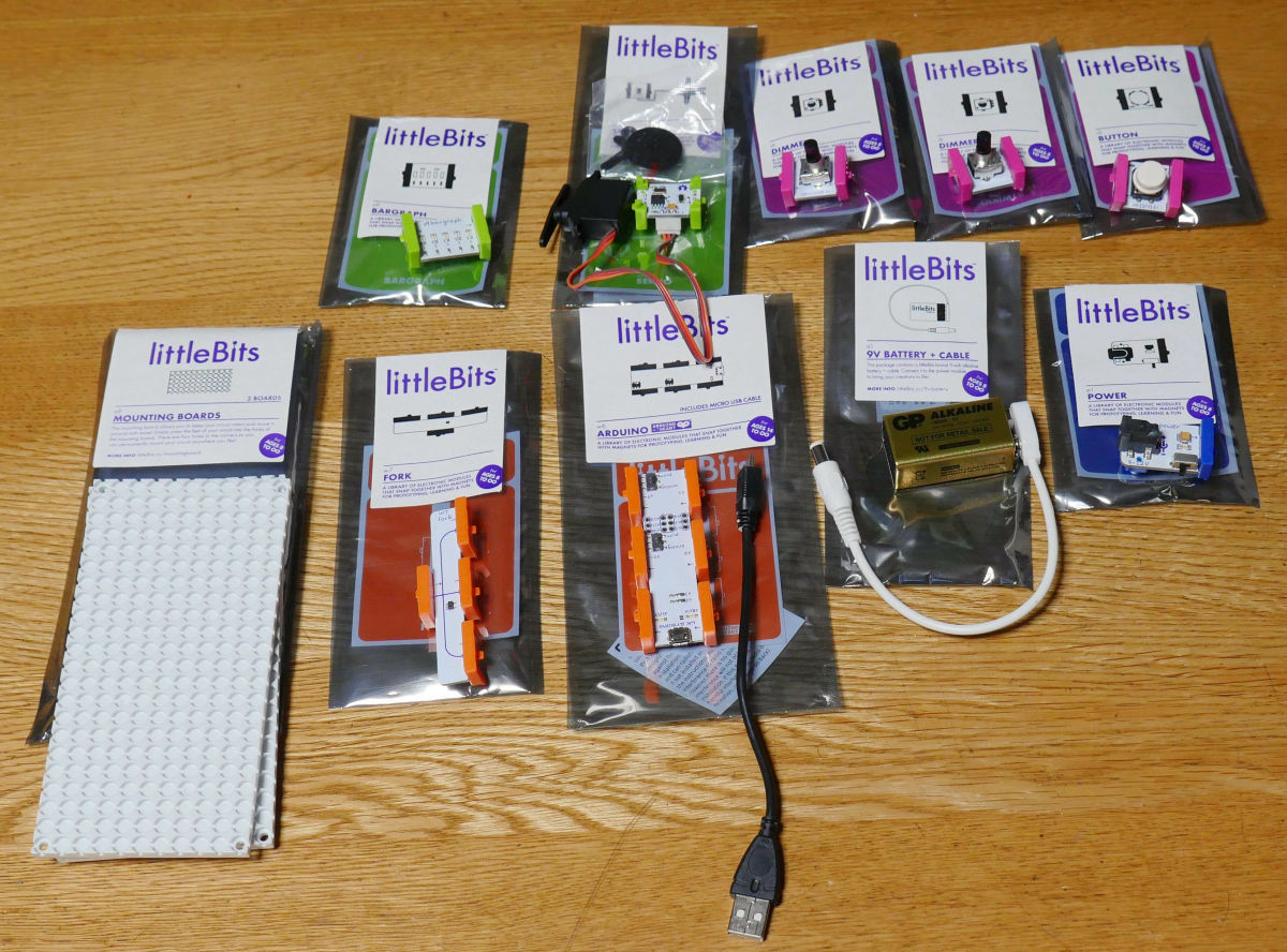
Taking out the module from the antistatic bag is like this. The mounting board on the bottom left of the image is a new part that was not in the little Bits kit so far, so I am wondering how to use it.
◆ Building an Arduino programming environment
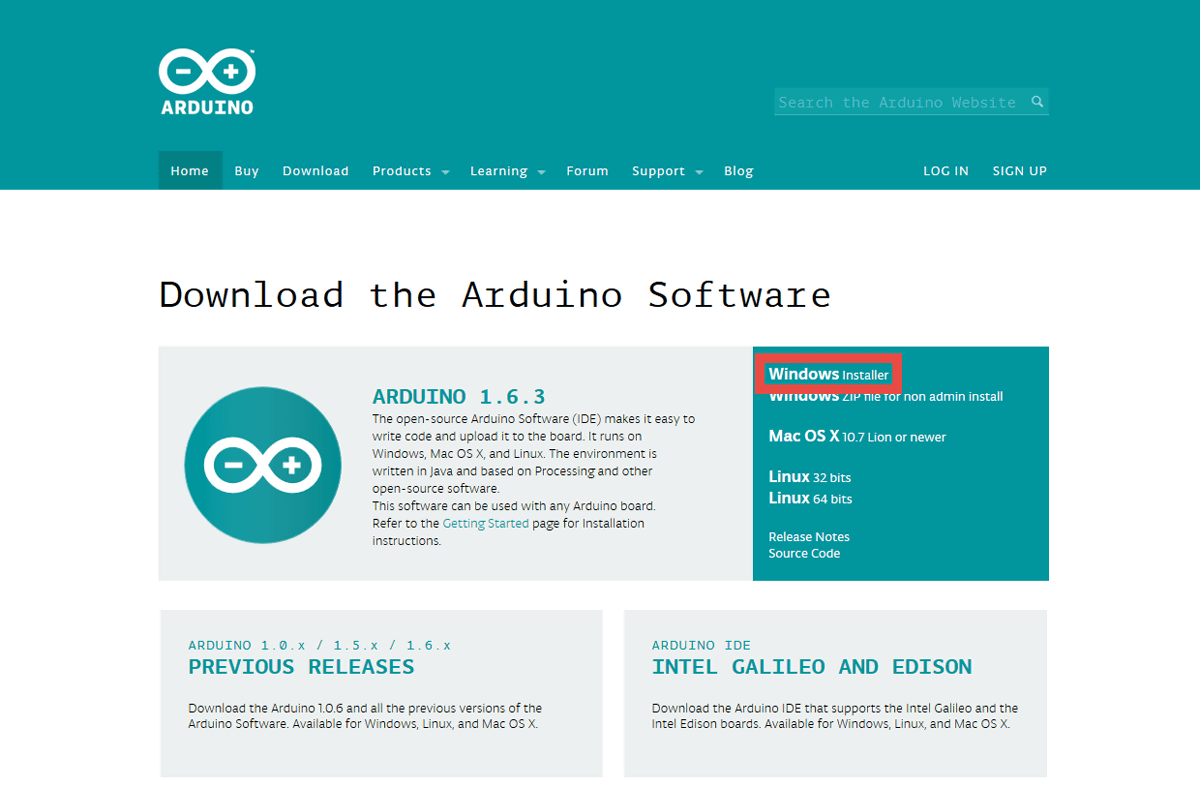
First, download the Arduino development environment (Arduino IDE).
Arduino - Software
http://arduino.cc/en/main/software
Since this time I will create a sketch (program plan) using a Windows machine, click "Windows Installer" at the above site.
Click "JUST DOWNLOAD".

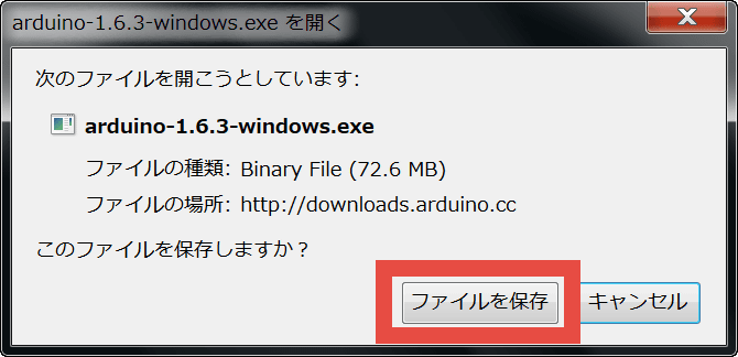
Click "Save file".
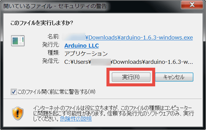
If security warning is displayed, click "execute".
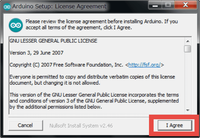
Click "I Agree".
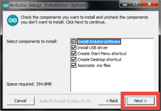
Click "Next".
Click "Install".

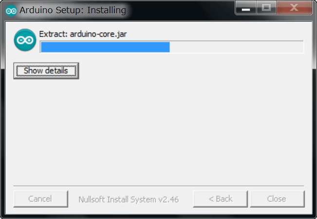
Installation begins.
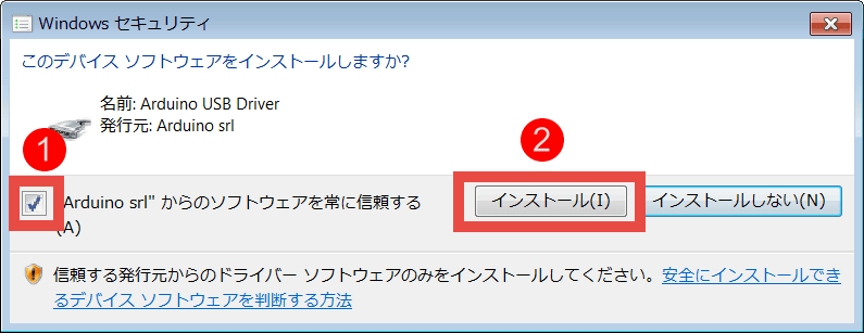
Since a security alert will appear on the way, please click on "Install" after checking.
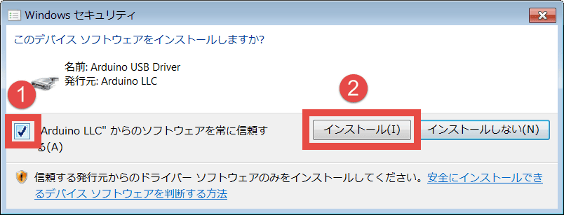
As you can ask again with the same feeling again, please check the same way and click "Install".
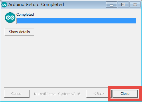
Once installation is completed click "Close" and close the window OK.
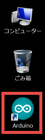
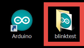
Double-click the "Arduino" icon on the desktop to launch "Arduino IDE".
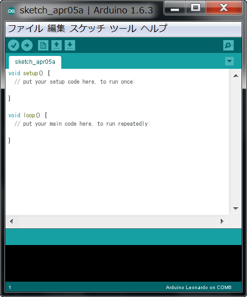
If such a screen is displayed Arduino IDE launched successfully.
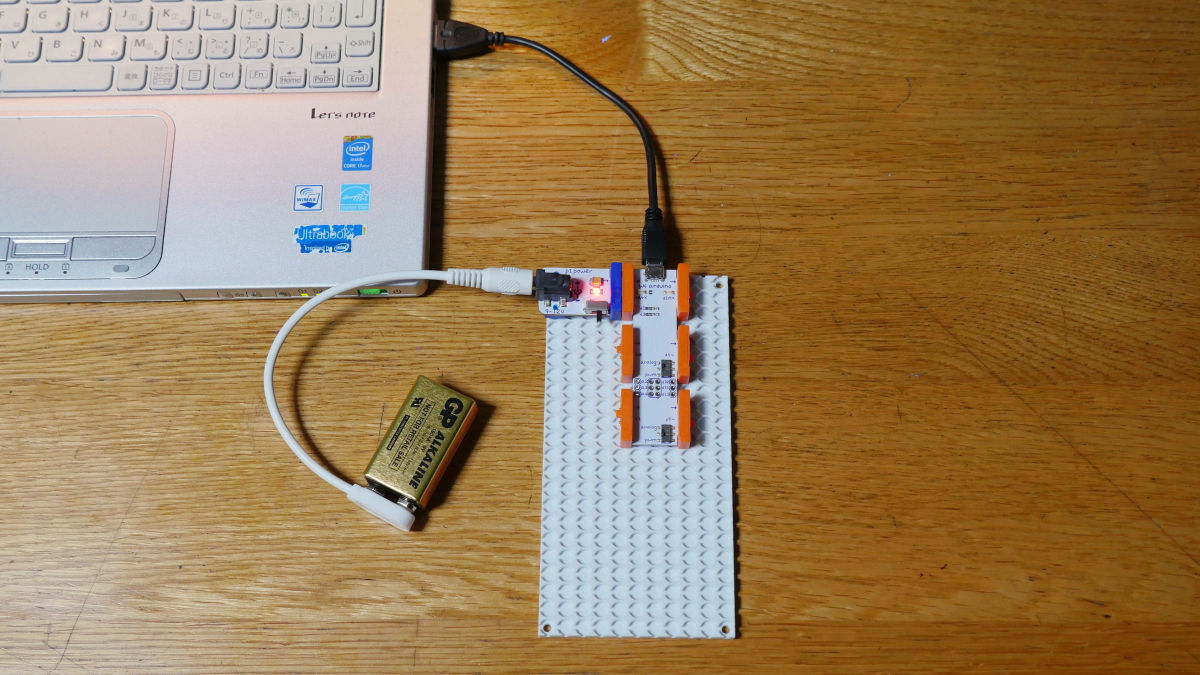
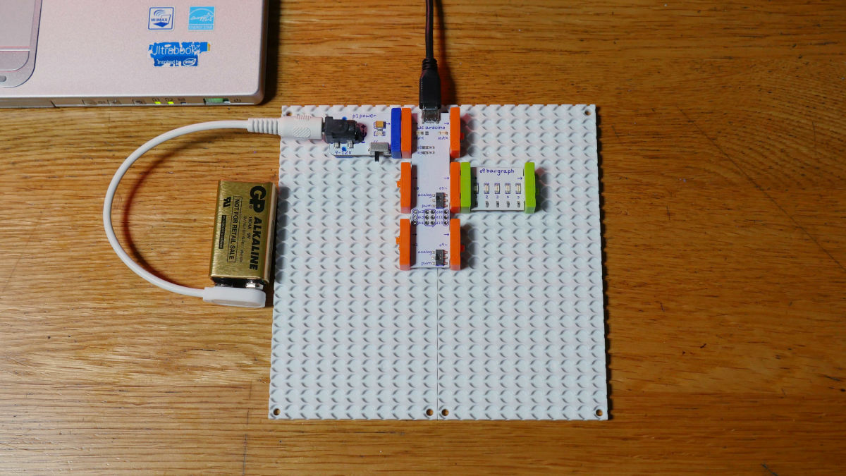
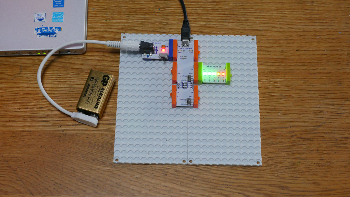
Next, connect Arduino to the PC using a USB cable. The new module "mounting board" functions as a base for firmly fixing Arduino and various modules. Unlike ordinary Arduino, Arduino of littlebits must be powered separately, so please be careful as PC can not recognize battery module unless you connect it like photo.
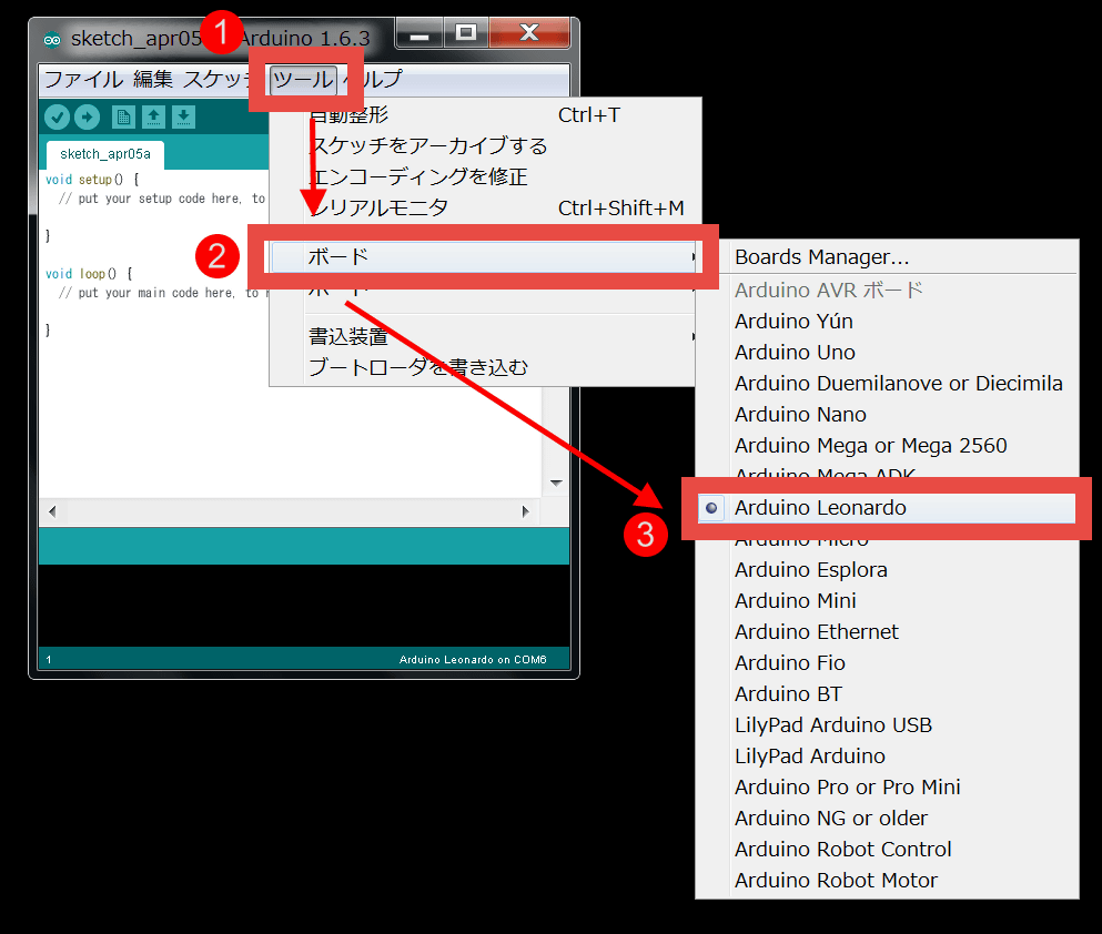
When connection with the PC is completed, select "Tools" → "Board" → "Arduino Leonardo" in the Arduino IDE menu bar.
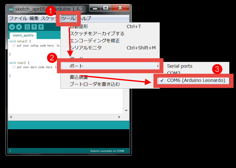
Further, select "Tools" → "Port" → "COM 6 (Arduino Leonardo)". If COM 6 (Arduino Leonardo) is not displayed here, connection has failed, so you need to reconnect the Arduino and PC. Once you have set up so far, quit Arduino IDE once.
At last the writing of the program to Arduino.LittleBits official websiteThere is a sample code that can be used with Arduino Coding Kit, so let's try this first.
Arduino Sketches
http://littlebits.cc/arduino-sketches
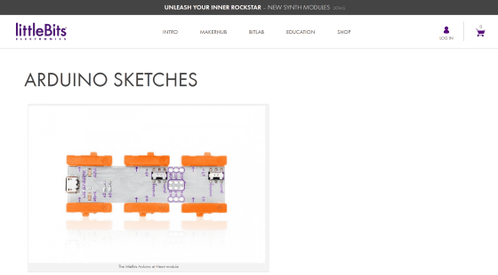
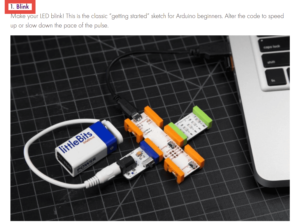
◆ Program to flash the LED light
Try using the sample code "Blink" on the above page. Click "Blink".
Since the pages change, click "Blink" in "ADDITIONAL FILES".
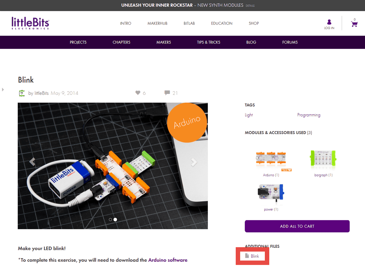
Check "Save file" and save the file "blink.ino" in a suitable place such as the desktop.

Next, connect the green "bargraph" as a module for Blink to Arduino.
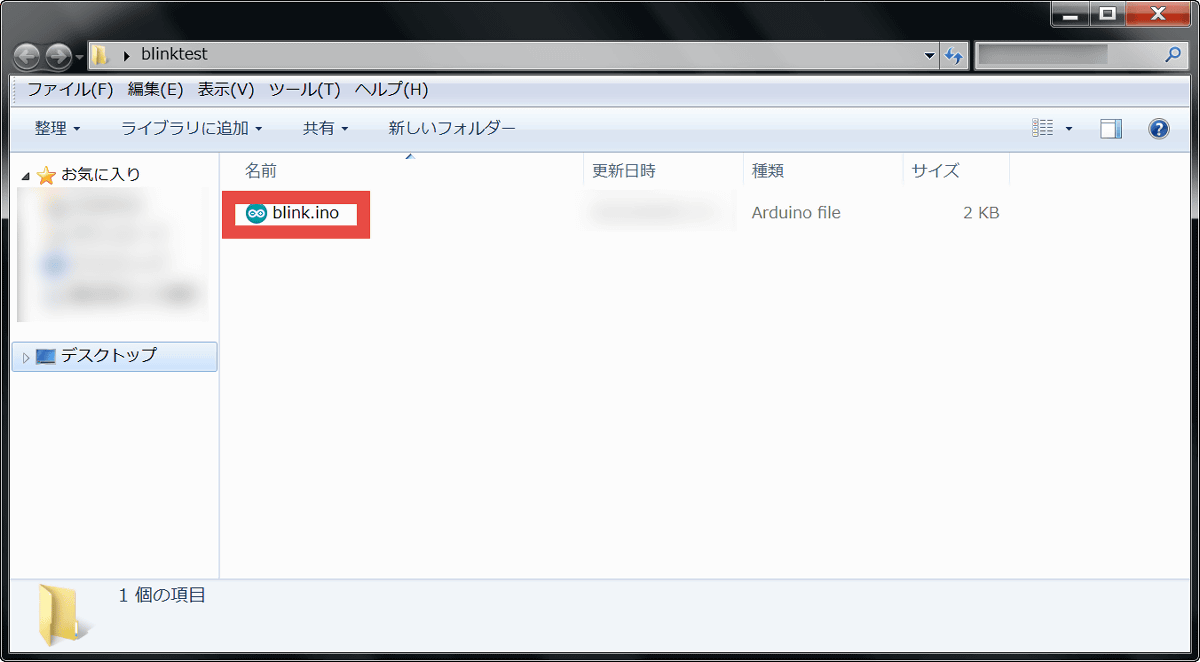
After connecting the module, create a folder called "blinktest" on the desktop, and copy blink.ino into it.
Run blink.ino in the folder.
Click "OK".
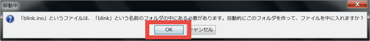
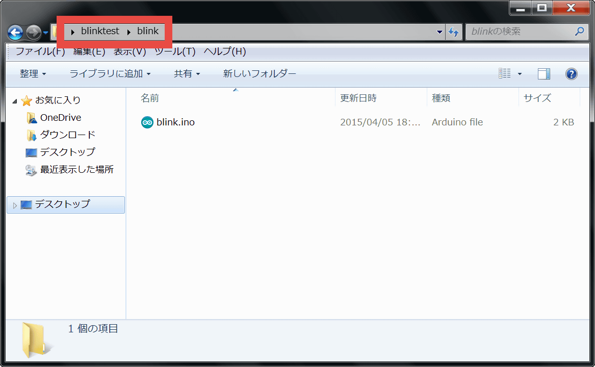
Then a folder named "blink" was newly created in blinktest's folder, and blink.ino was automatically stored in it.
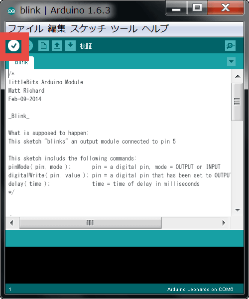
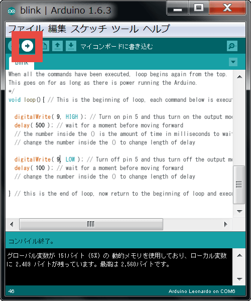
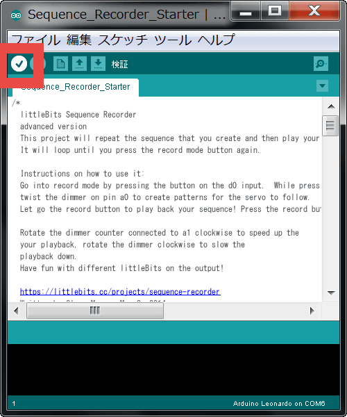
When this screen is displayed, click the "check button (verification button)" at the bottom of the menu bar.
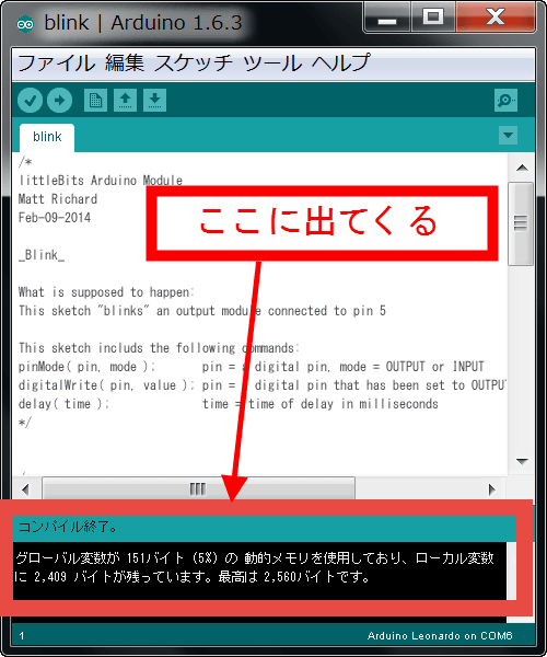
If there are no errors, the end of compilation is displayed on the bottom console screen.
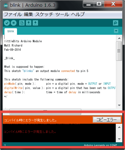
If there is a syntax error etc., an error is displayed on the console screen, so you need to rewrite the program.
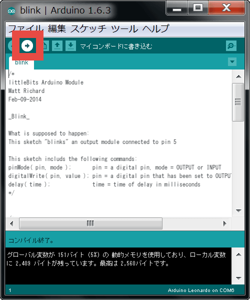
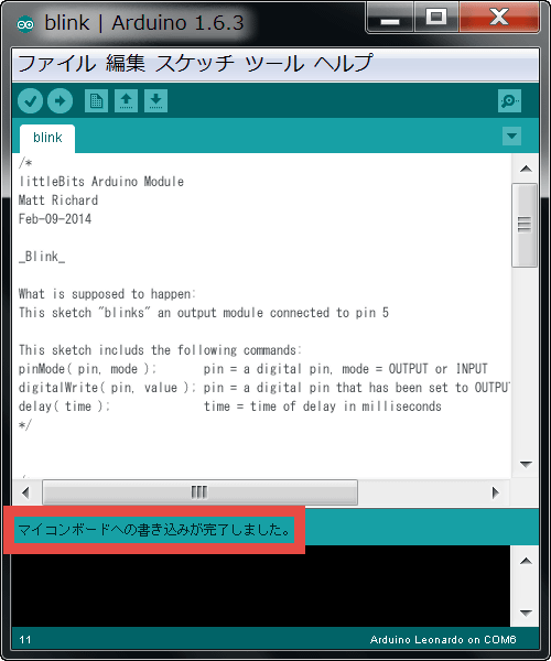
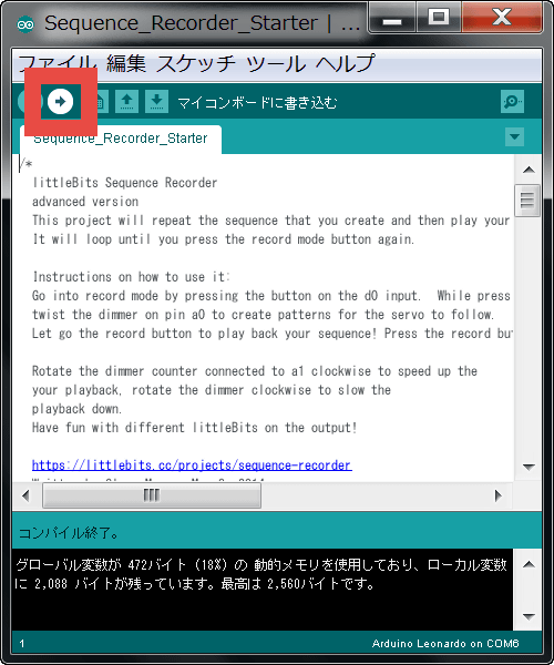
Next I write the compiled program to Arduino. Click the "write button" in the red frame.
Successful writing if "Writing to the microcomputer board is completed" is displayed.
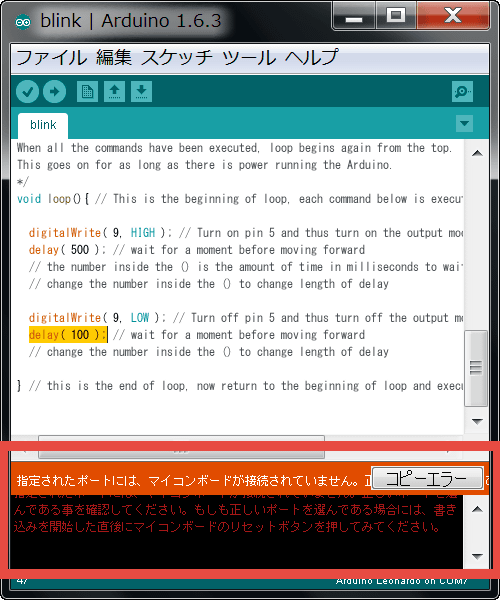
In addition, if writing fails, an error will be displayed, so you need to reconfirm the Arduino connection.
The following movie shows you what kind of change will occur in the sample code "Blink".
Try the sample program "Blink" with little Bits "ARDUINO CODING" - YouTube
The bargraph module flashed. The sample program "Blink" seems to have written the command "Flashes the bargraph module". In this way, by writing your sketch as a program design drawing yourself, you can issue instructions to Arduino.
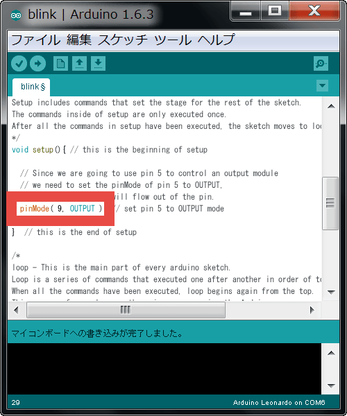
Next, I will rewrite the contents of sketch Blink. The place called "pinMode (5, OUTPUT);" on the 29th line of the program ... ...
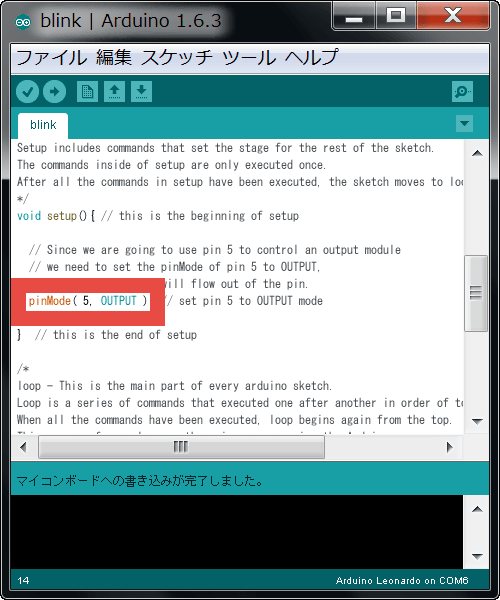
Changed to "pinMode (9, OUTPUT);".
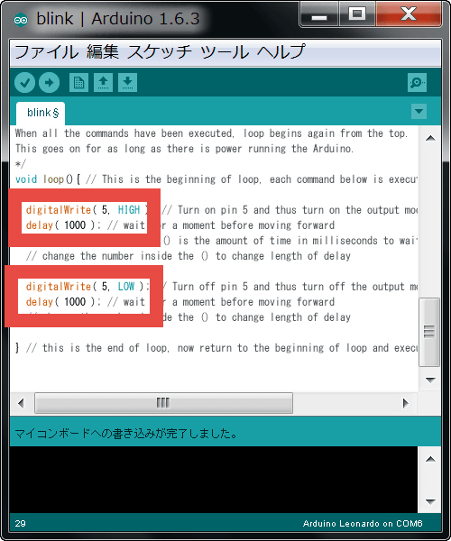
"DigitalWrite (5, HIGH);" "delay (1000);" "digitalWrite (5, LOW);" "delay (1000);" in the program line 41 to line 47 ......
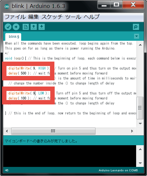
"DigitalWrite (9, HIGH);" "delay (500);" "digitalWrite (9, LOW);" "delay (100);
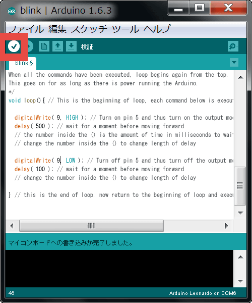
After clicking "Verification button" just as before ... ...
Click "Write button".
You can see changes in program contents in the following movies.
Modify program "Blink" with little Bits "ARDUINO CODING" to change flashing behavior - YouTube
The position of the target pin (module terminal) of the instruction to blink is changed from "5" to "9", and the blinking interval has also been changed. In this way, by watching the sample program frankly, changing the numerical value in the middle is a mechanism whereby the meaning of the parameter gradually becomes known and the programming skill is up while the program is rewritten and executed.
◆ Program for operating the servomotor
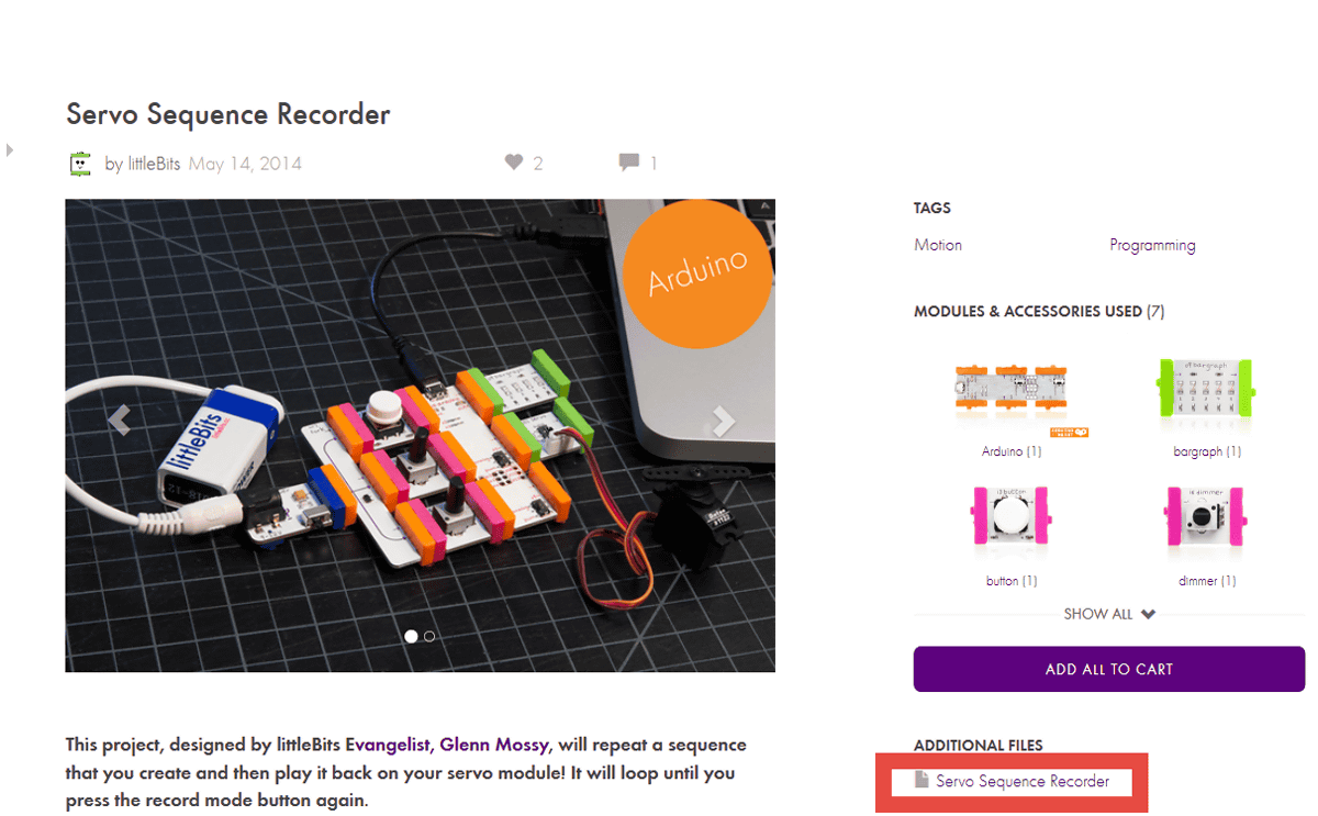
Next, let's run a more complicated program. Click the sample code "Servo Sequence Recorder" on the official site.

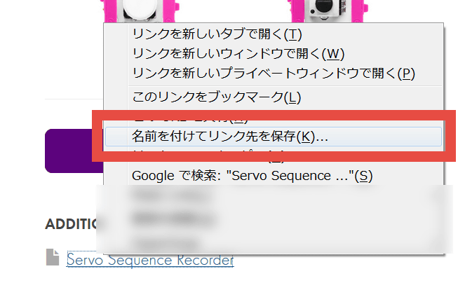
Right click "Servo Sequence Recorder" under ADDTIONAL FILES in the lower right ... ...
Click on "Save Link Target As". Save the file "Sequence_Recorder_Starter.ino" wherever you want, such as the desktop.
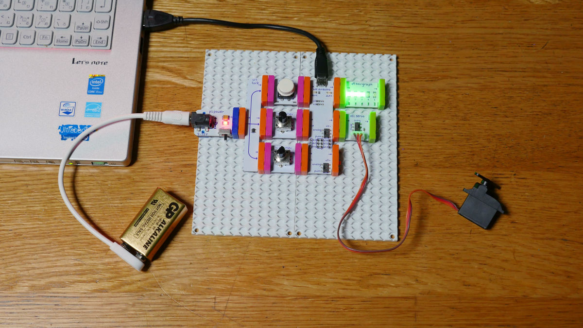
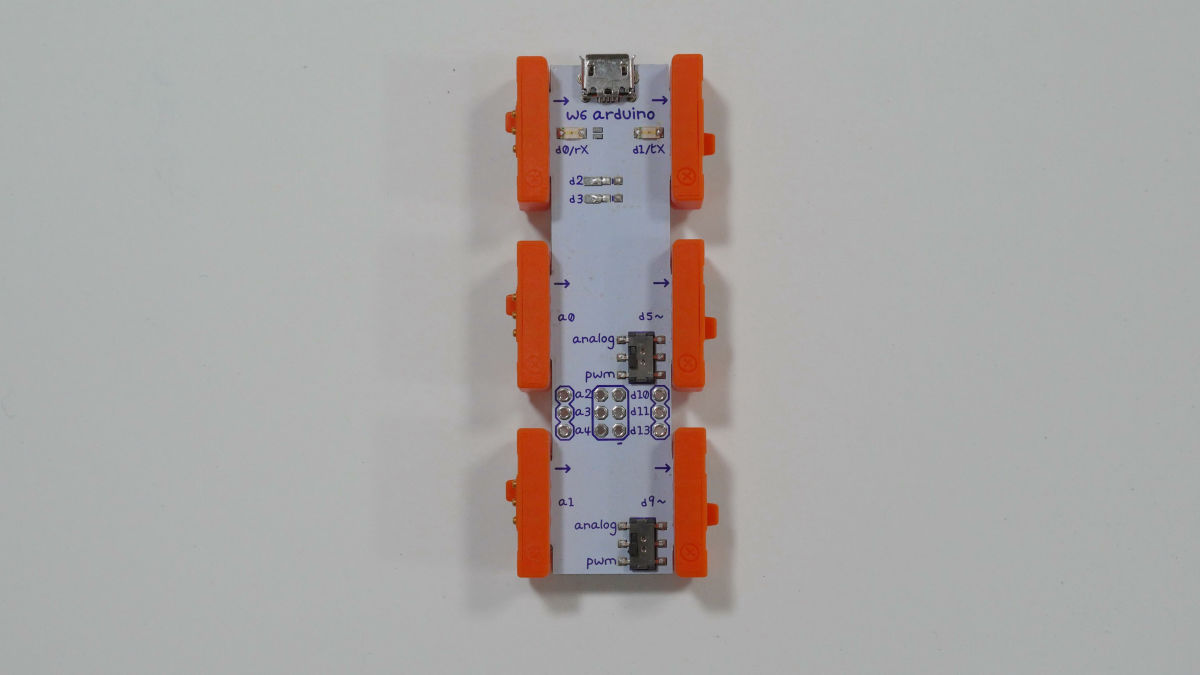
After saving the file, attach "dimmer" "button" "bargraph" "servo" to Arduino.
Double click on Sequence_Recorder_Starter.ino that you saved earlier and click "OK".

Click the Verify button.
Click the write button.
You can check the motion in this state with the following movie.
Sample code 'Servo Sequence Recorder' does not work properly with littleBits + Arduino - YouTube
Because somehow it does not work properly, we found out the cause and found that the remaining capacity of the battery is insufficient. Therefore, I decided to remodel so that little Bits messing can be done without worrying about the remaining battery level by making AC adapter instead of Power module + battery. I used what I used to purchase "Clever AC adapter DC 9 V 1.3 A (WN - 09130 P)".

By making AC adapter, program Servo Sequence Recorder can be moved safely. The behavior of the dimmer attached to the a 0 pin is recorded only while the button is pressed and the behavior showing that the recorded contents are reflected on the servomotor when the button is released can be confirmed with the following movie.
I tried writing sample code "Servo Sequence Recorder" with littleBits + Arduino - YouTube
In addition to the a 0 pin dimmer, you can also change the input of a 1.
So, let's change the program at once. The part commented out by "/" in line 113 to 115 in the program ......
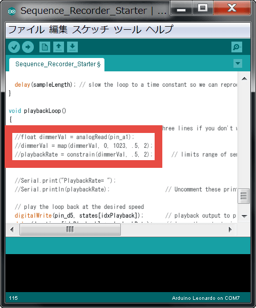
Remove "/" and activate it. By doing this, the input of the pin connected to a1 turns ON, and turning the dimmer of a1 can speed up or slow down the movement recorded on the servomotor.
Click the Verify button.
Click the write button.
The movement after the program change can be seen in the following movie.
Servo Sequence Recorder "sample code of little Bits to adjust servo movement - YouTube
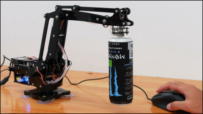
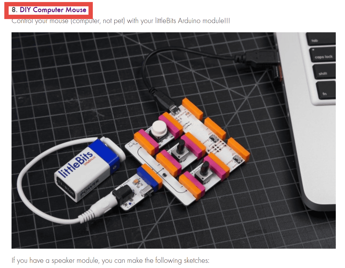
◆ Program that manipulates the mouse
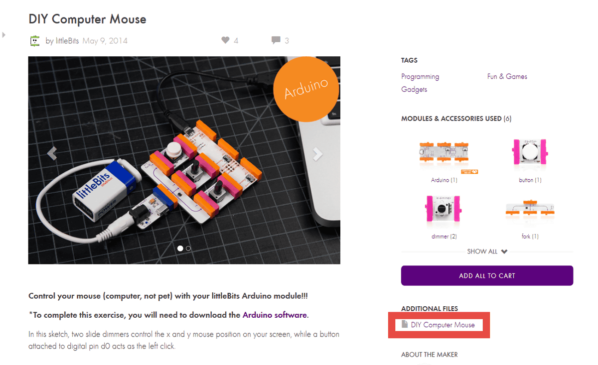
Next time I will make a more practical PC device. Click on the little program "DIY Computer Mouse" of the little Bits official site.
As the page switches, click "DIY Computer Mouse" under ADDTIONAL FILES in the lower right.
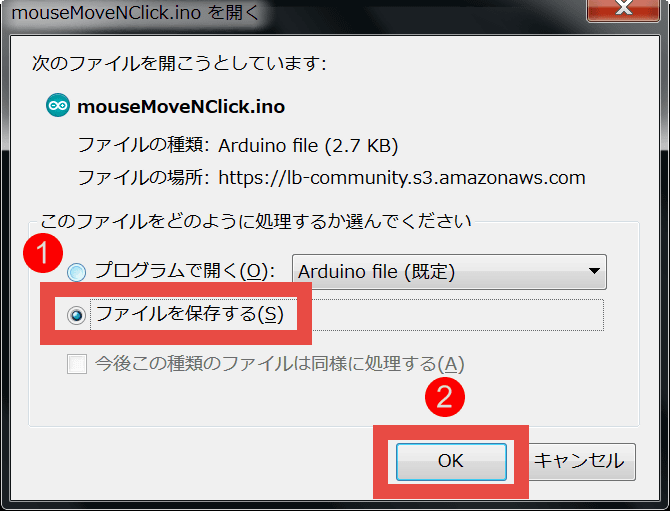
Check "Save file" and click OK to save the file "mouseMoveNClick.ino".
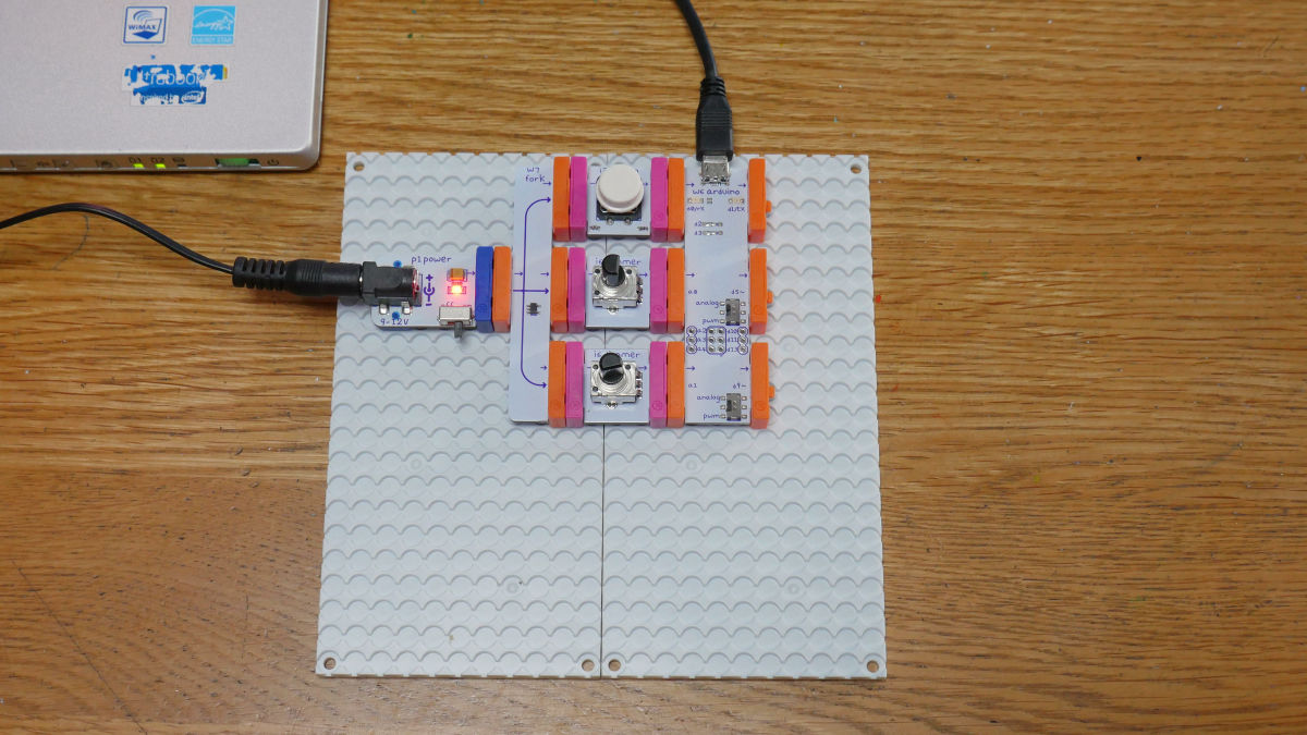
Before writing the program, install "dimmer" "button" "Arduino module" in Arduino and connect it with the PC with the USB cable.
When you start up the saved file mouseMoveNClick.ino with double click, you will be asked if you want to create a folder automatically and click "OK".

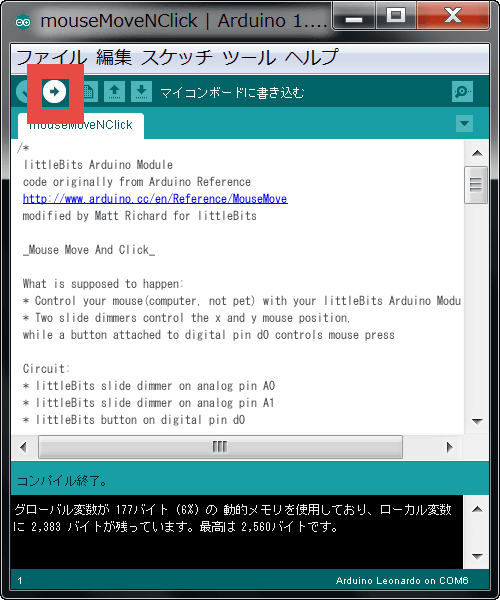
Click "Verify Button" → "Write Button" in this order.
You can now move the mouse cursor with a dimmer or click with the button.
How to operate Windows machine instead of mouse with littleBits + Arduino - YouTube
It is also possible to monitor mouse operation. First delete the comment-out "/" in line 49 to 51 of the mouseMoveNClick.ino program and activate it.
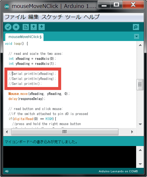
Click "Verify Button" → "Write Button" in this order.
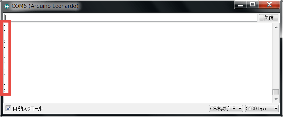
Click the serial monitor button.
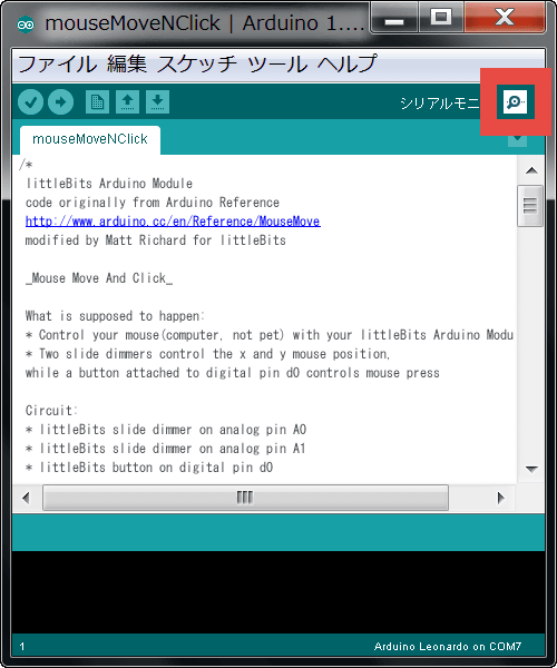
Then, the monitoring screen in which the numbers "0" are arranged like this is displayed like this.
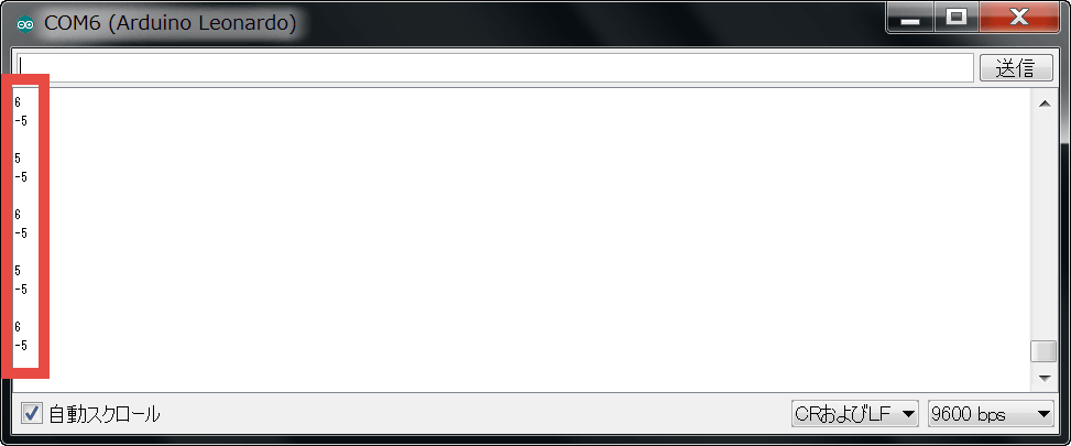
Move the dimmer for testing and the value will change accordingly. Since the numerical value is a small number such as "-5" or "6", it seems that it indicates the relative position with the mouse cursor as the center point instead of directly specifying the screen coordinates.
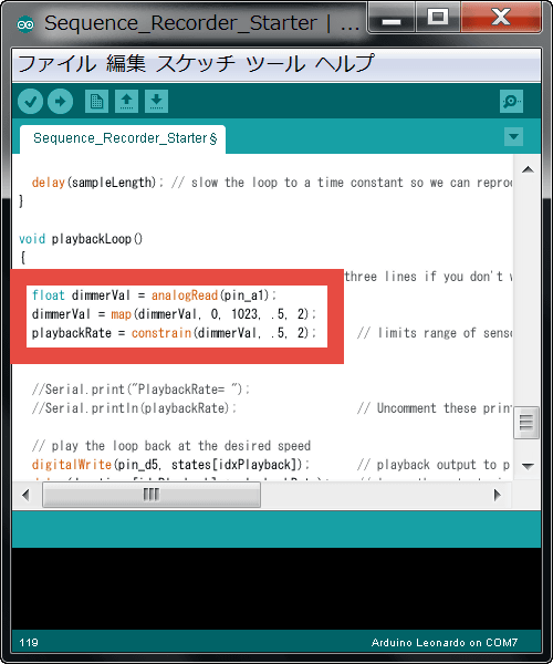
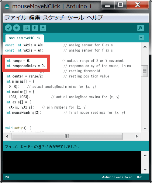
You can also change the cursor movement amount and reaction speed by rewriting the numerical values like the image below.
◆ Processing program
Finally, visual design "ProcessingLet's challenge the program using.
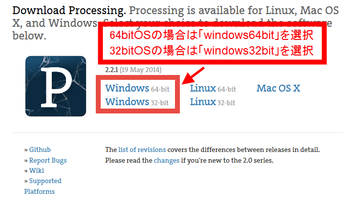
Download \ Processing.org
https://processing.org/download/?processing
Download Processing corresponding to the OS used from the above site to the desktop or any other place you like.
Download the downloaded file as "ExplzhExtract it with "processing.exe" in the folder.
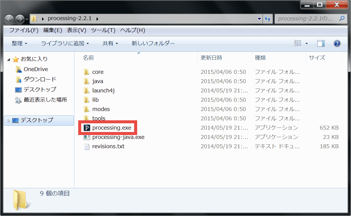
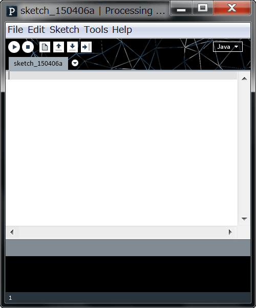
When this window opens, click "X" to exit the window. The adjustment of the environment variable is completed with this. You can open the pde file used for Processing from anywhere.
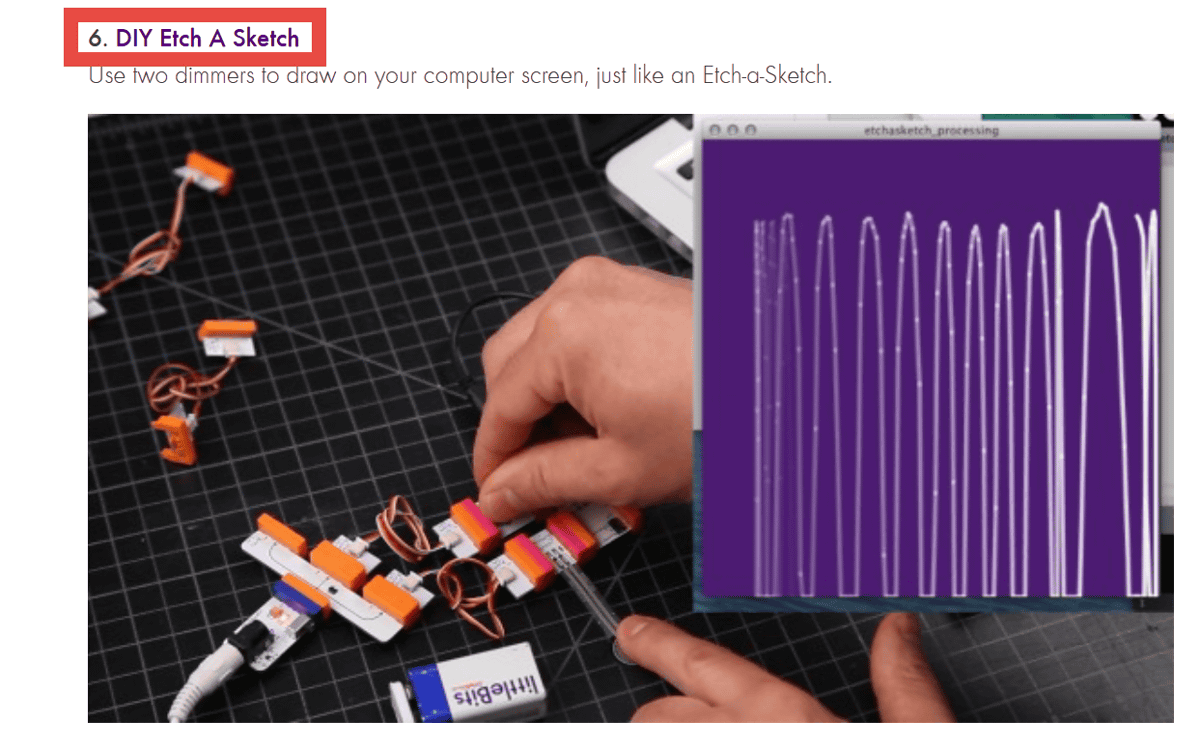
Little bitOfficial pageTry the sample code "DIY Etch A Sketch" at
Click "DIY Etch A Sketch".
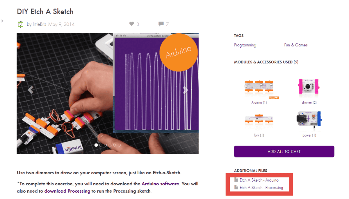
As the page moves, click "Etch A Sketch - Arduino" and "Etch A Sketch - Processing" under ADDTIONAL FILES in the lower right to save "etchasketch_arduio.ino" "etchasketch_processing.pde" respectively.
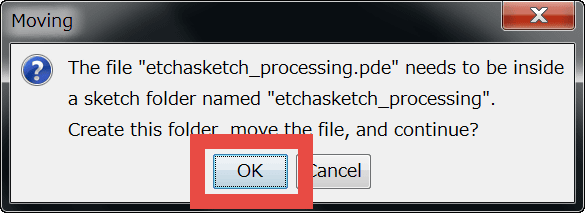
When you run etchasketch_arduio.ino, you will be prompted to automatically generate a folder, so click "OK".

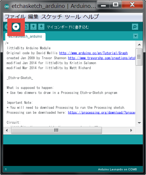
Click "Verify Button" → "Write Button" in this order.
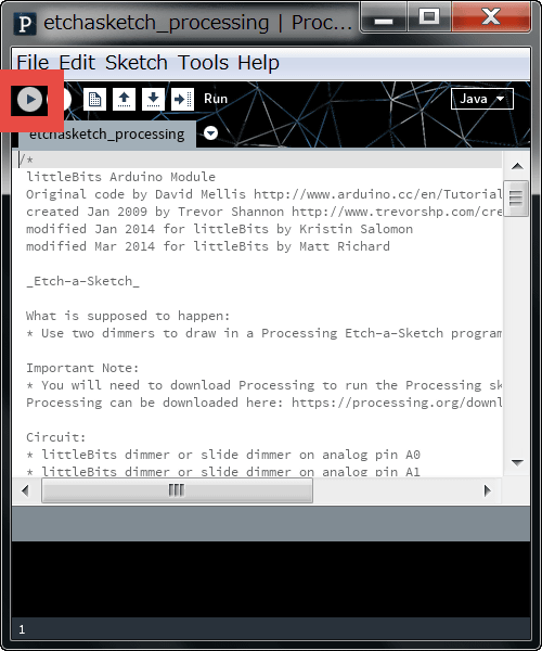
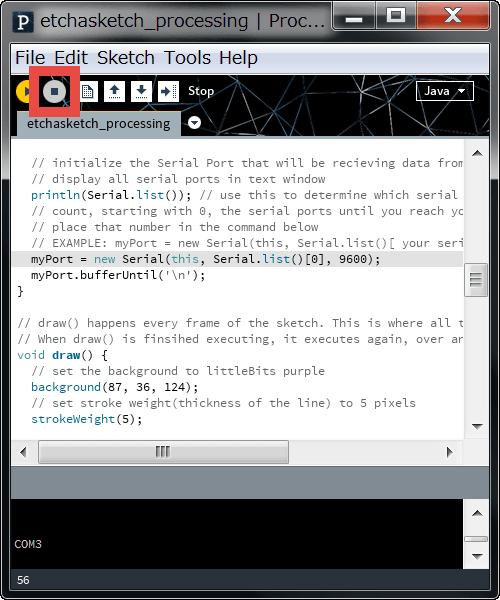
When you execute etchasketch_processing.pde, you will be asked if you want to create a folder automatically, so click "OK".
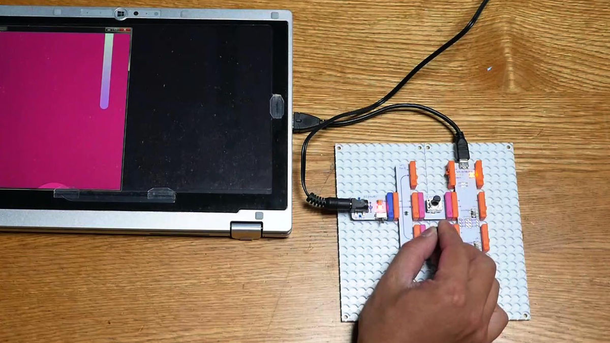
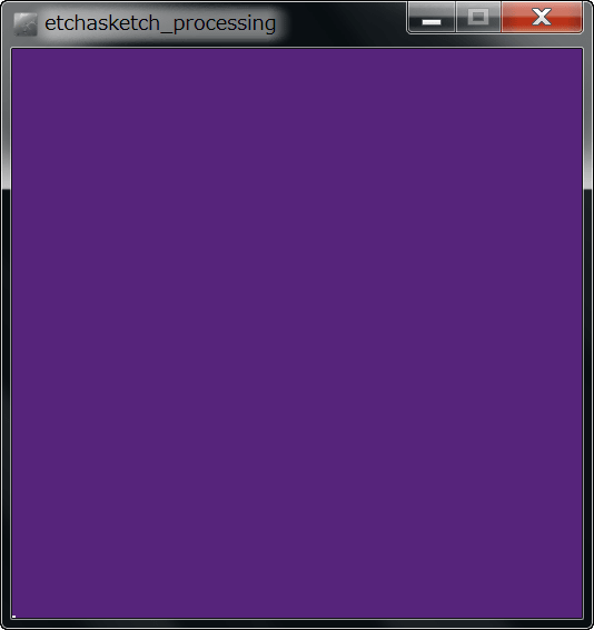
If you run it as it is ... ...
The screen turned purple, no response even if you manipulated the dimmer.
For now, click the "stop button" to stop the program.
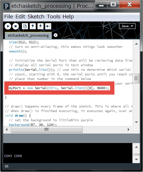
"MyPort = new Serial (this, Serial.list () [0], 9600);" in the 56th line of the program ......
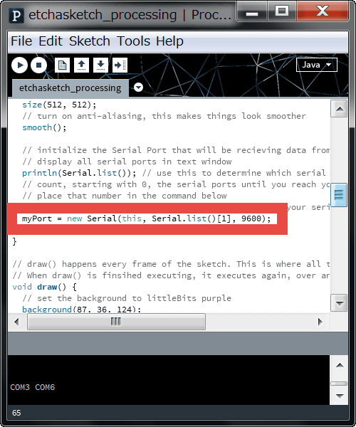
Change it to "myPort = new Serial (this, Serial.list () [1], 9600);" Please note that the numbers in brackets [] are connected to the COM port on the PC, so if you change the number according to your environment it is OK.
Run the program again.
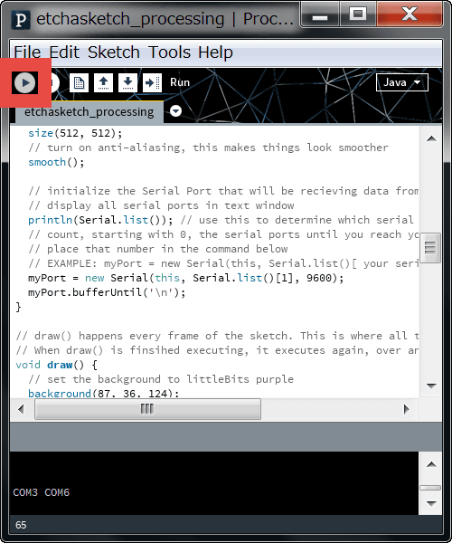
In this way, you can "paint on" purple canvases by manipulating the dimmer.
Run Processing program with littleBits + Arduino - YouTube
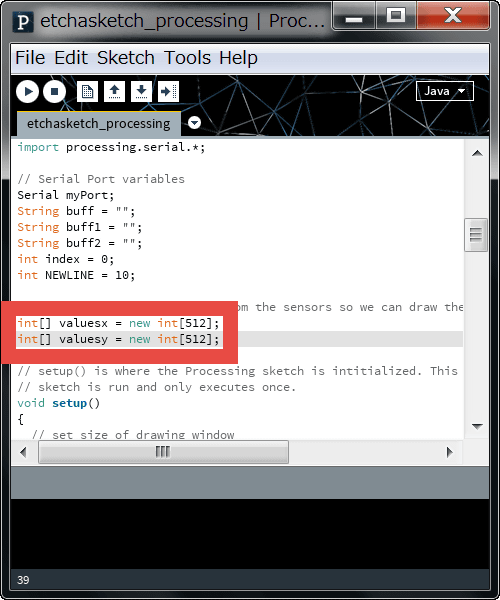
Also, "int [] valuesx = new int [256];" on the 38th line of the program and "int [] valuesy = new int [256];"
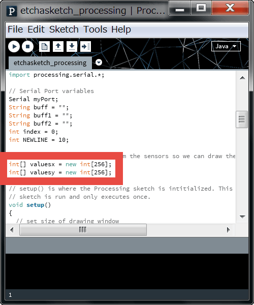
"Int [] values x = new int [512];", "int [] valuesy = new int [512];
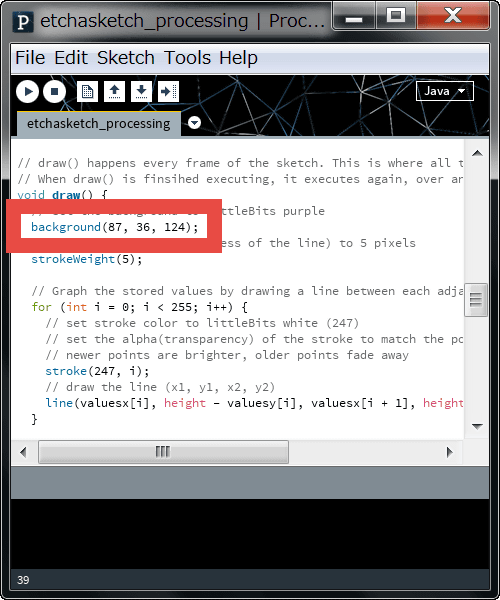
Delete "background (87, 36, 124);" on line 64. In addition, this part has RGB values of the background color.
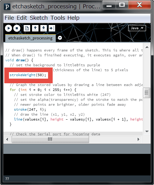
"StrokeWeight (5);" on line 65 ... ...
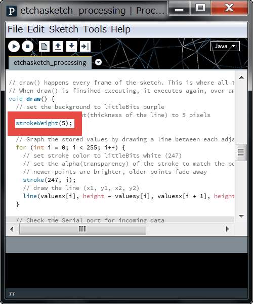
Changed to "strokeWeight (50);". This part specifies the thickness of the line to be drawn.
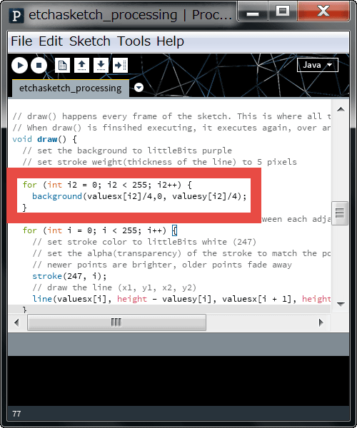
Furthermore, on line 66「for (int i2 = 0; i2 < 255; i2++){background(valuesx[i2]/4,0,valuesy[i2]/4);}」I will add it.
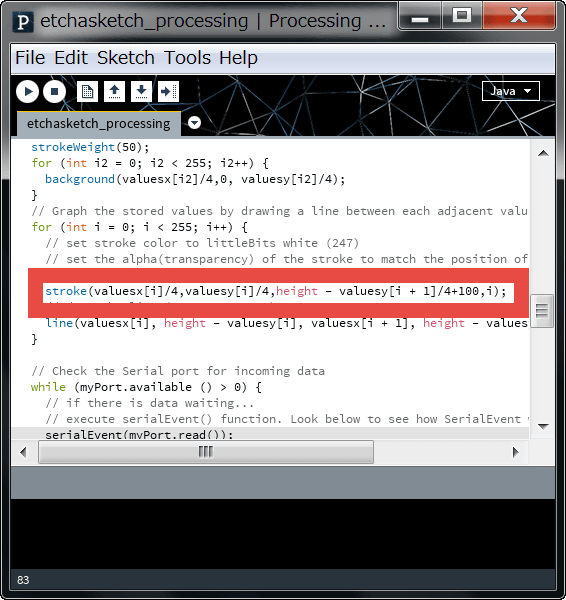
"Stroke (247, i);" on line 76 ... ...
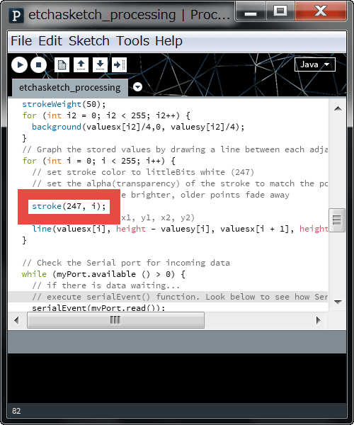
And change. This is the part that specifies the color (RGB) and transparency of the line.
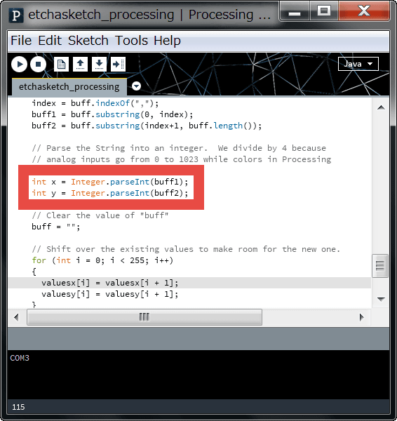
Then, "int x = Integer.parseInt (buff 1) / 2;" on the 109th line and "int y = Integer.parseInt (buff 2) / 2;" on the 110th line are ...
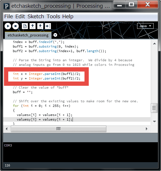
"Int x = Integer.parseInt (buff1);" "int y = Integer.parseInt (buff2);"
Now run the program.
In this way, the drawing window became bigger, the thickness of the line became thicker, it was able to change so that the color of the background and the color of the line change according to the movement of the dimmer.
Rewrite the sample code of Processing and change the background color · line thickness etc and draw with little Bits + Arduino - YouTube
Impressions
It was difficult to make circuits of electronic block type so far to make circuits other than specific circuits. When using Arduino Coding Kit, you can virtually create timer circuits and recording circuits with programs, Since it can be received as a numerical value, it seems to say that the possibility of assembling a circuit expands.
In addition, "little Bits ARDUINO CODING KIT" which is a set of 8 kinds of modules is 12,000 yen (tax included).
ARDUINO CODING KIT product information - littleBits
http://jp.littlebits.com/kits/arduino-coding-kit/
Related Posts: