I tried assembling "Robodanbo" that you can walk and dance and move freely
Robotized "Danbo" appearing in the manga "Yotsubato!", 11 different servo motors are mounted on the whole body, various expressions such as "walking" "dancing" and so on are available and can be controlled wirelessly using the controller "VS-CS 3" I decided to actually assemble the kit "Robodanbo" that I can steer and move it.
Robodanbo (Danboard the Robot) | Viston Corporation
http://www.vstone.co.jp/products/danboard/
◆ Photo review
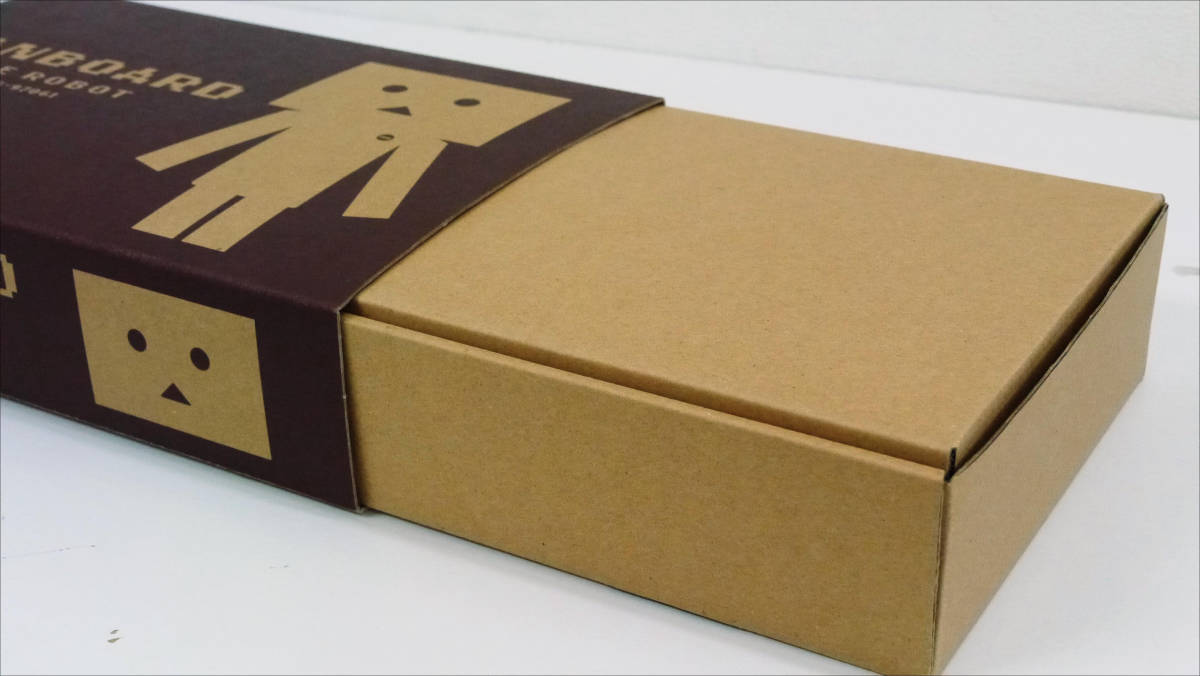
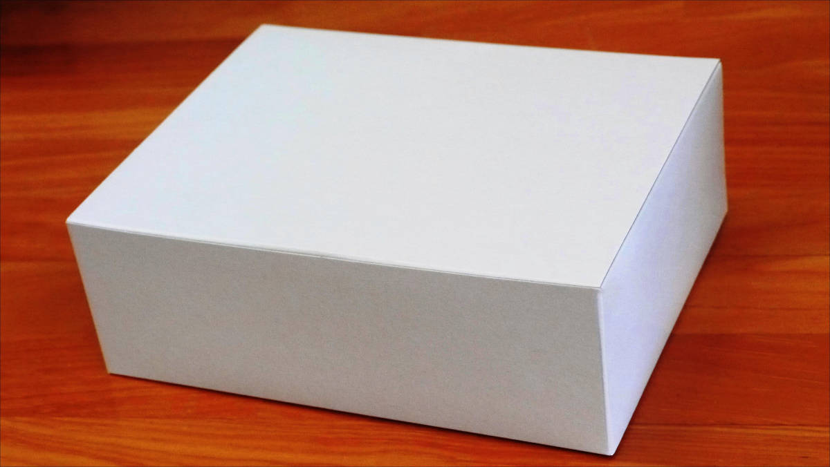
This is the box of Robodanbo.

Slide to open the box inside.
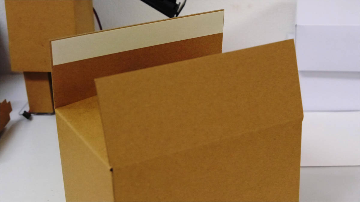
When you open the middle box and cardboard of the exterior part of Dan Bo ......
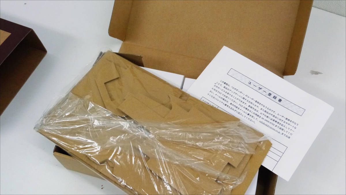
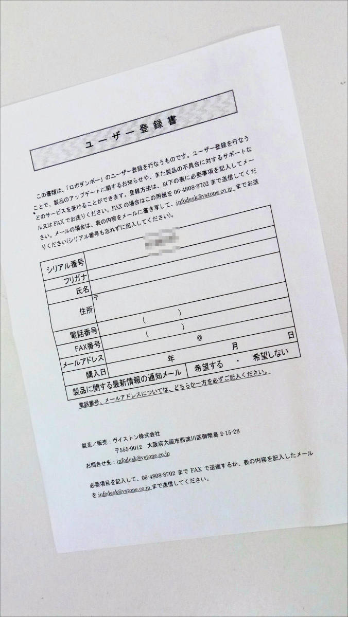
A user registration form is included.
Below that there are two white boxes.
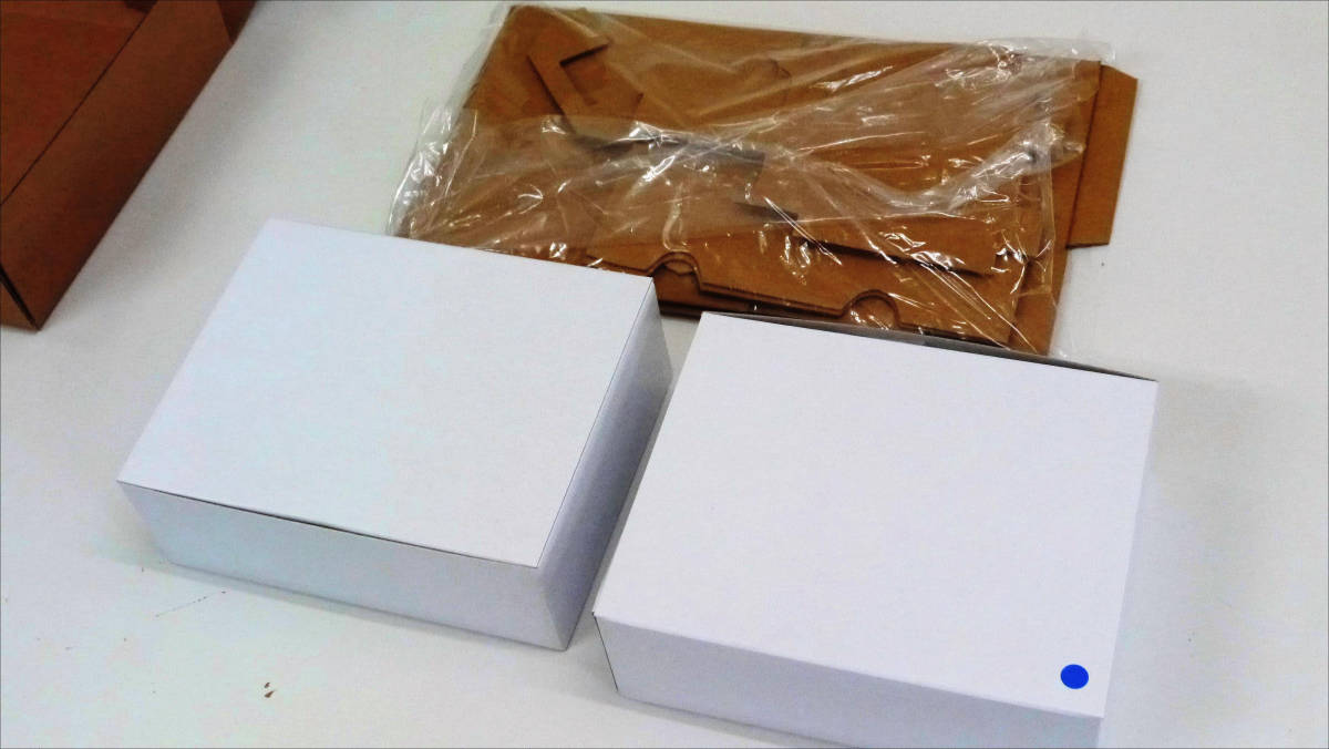
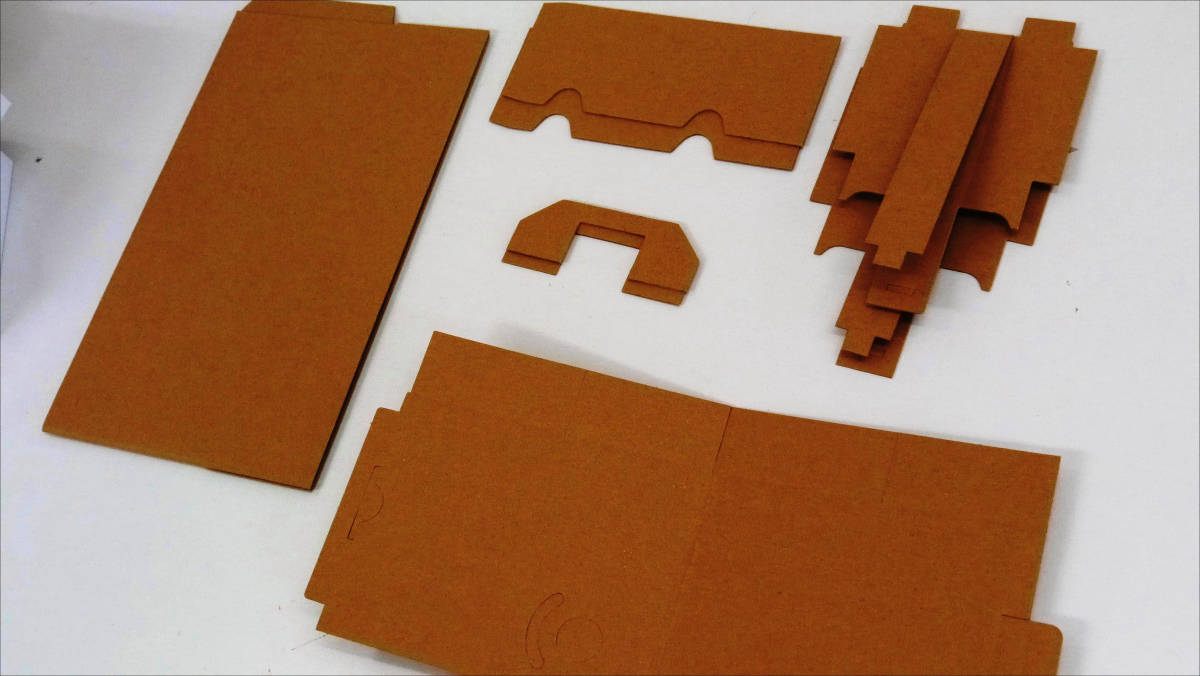
Expanding the exterior corrugated cardboard will look like this. There are not so many parts as I thought.
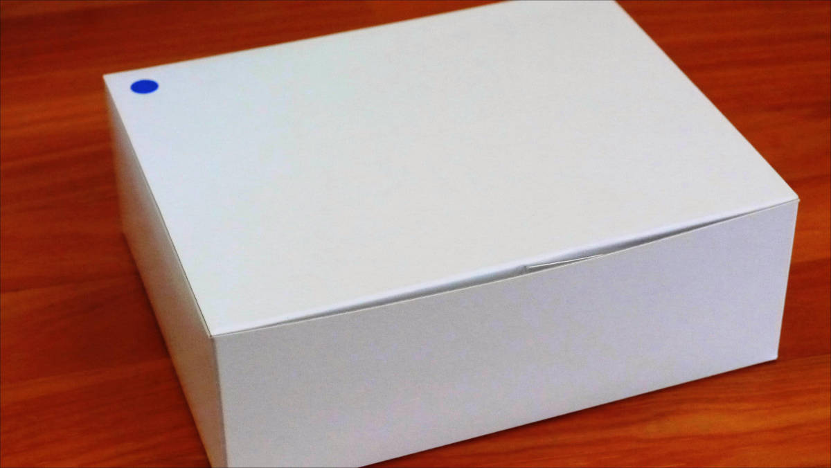
Then open the box with a blue seal.
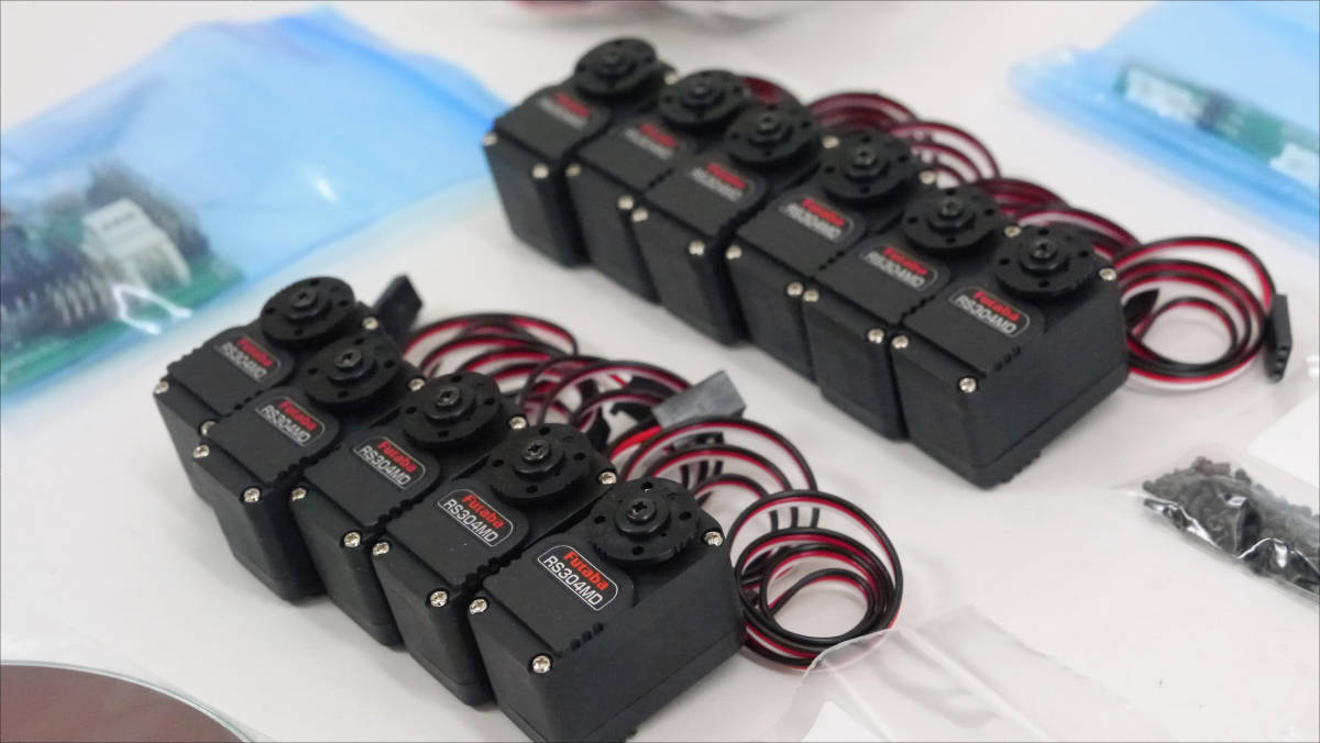
It is like this when arranging contents.
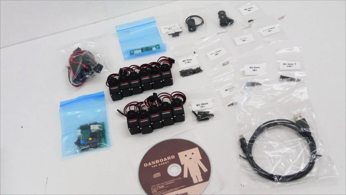
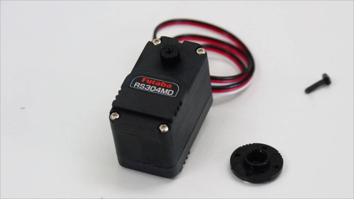
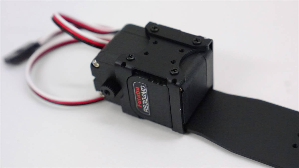
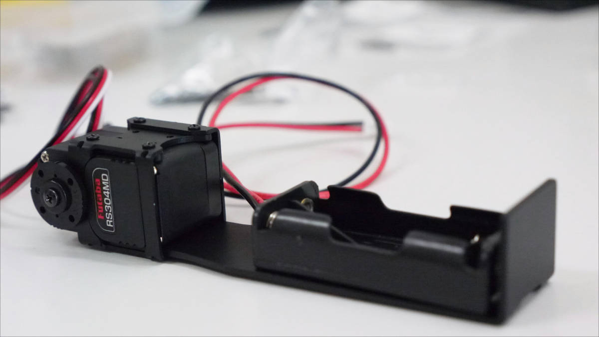
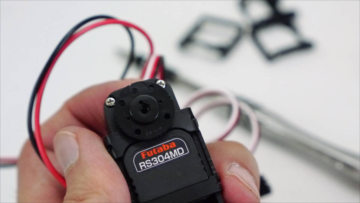
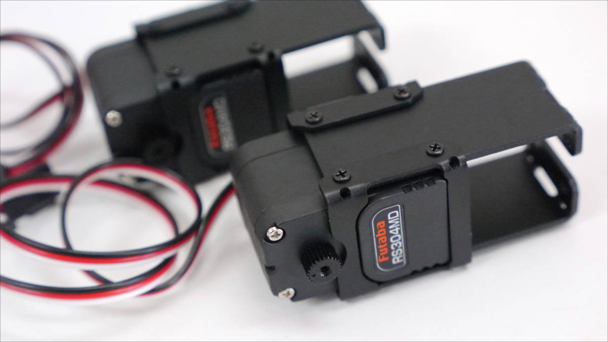
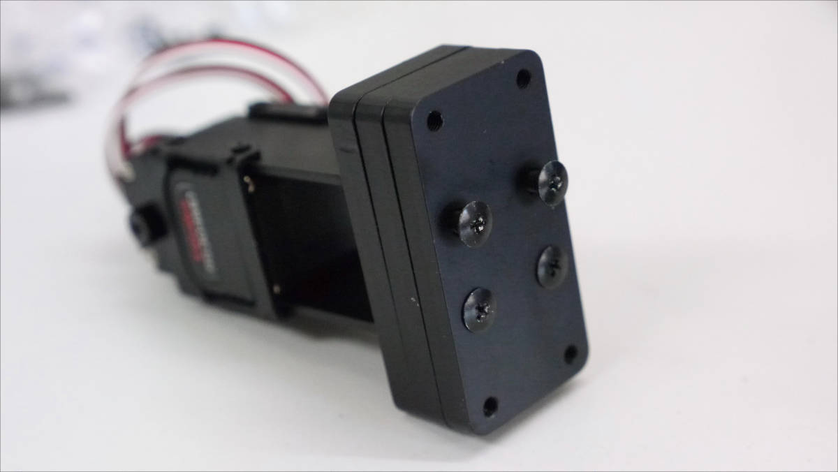
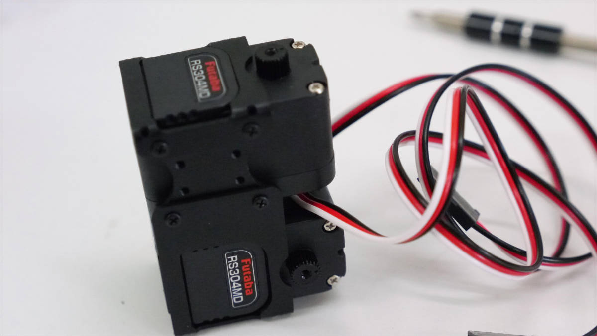
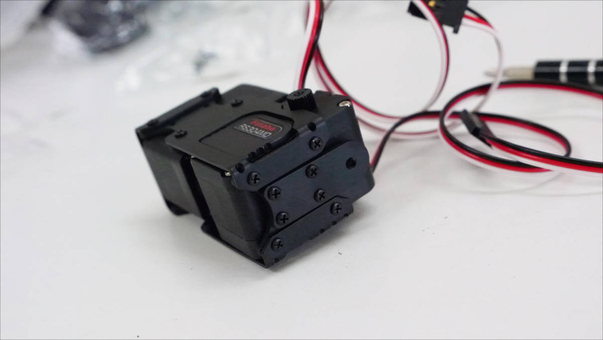
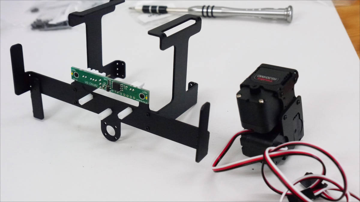
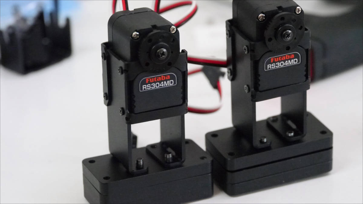
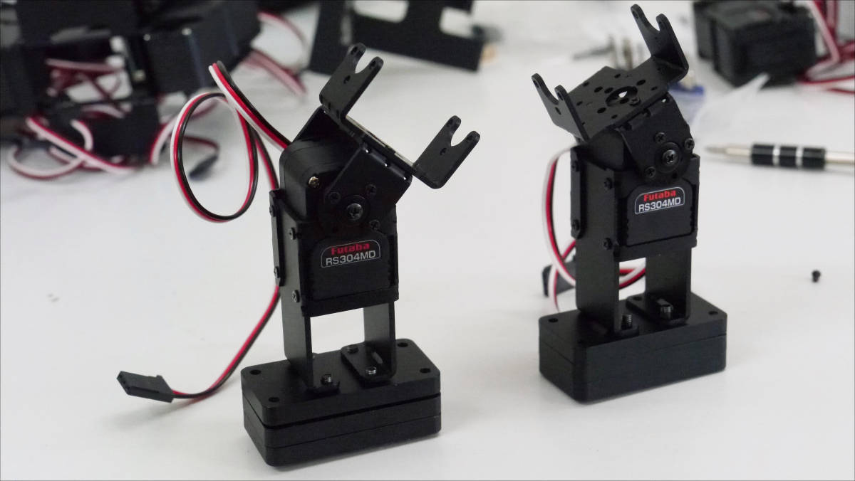
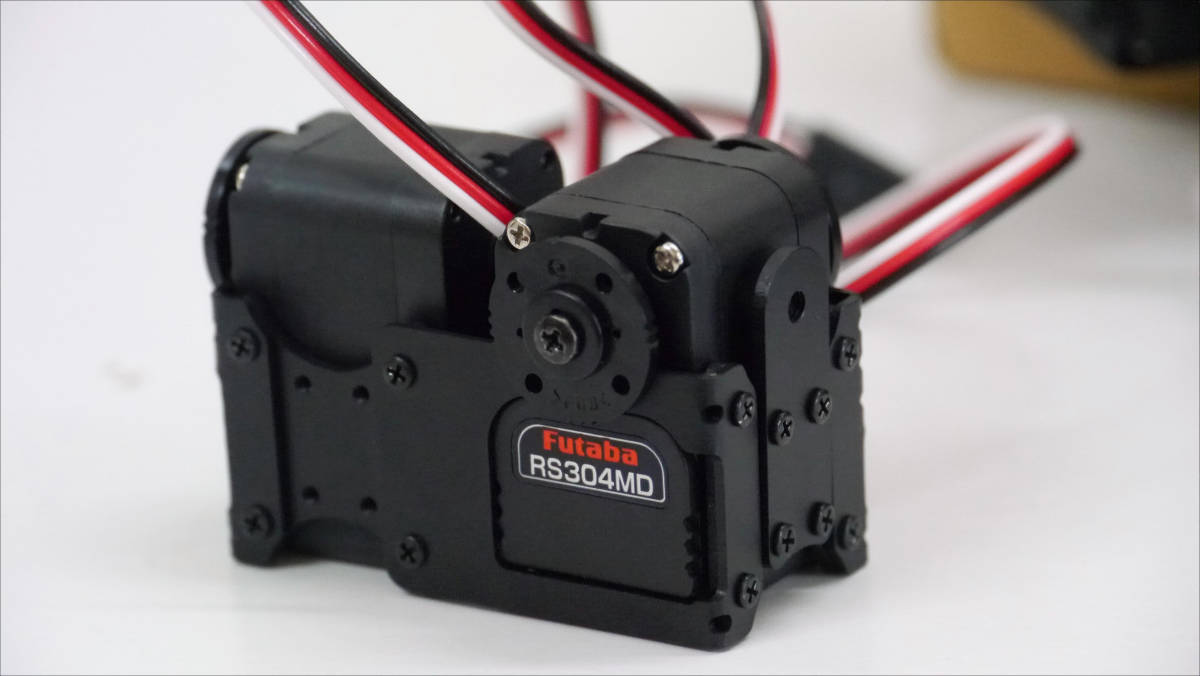
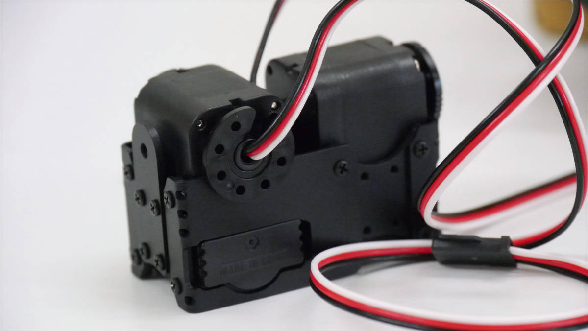
Servo is made by Futaba "RS304MD"is.
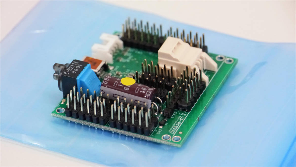
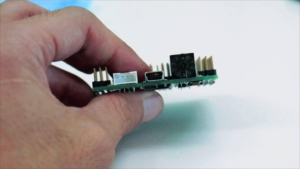
This is the CPU board at the heart of Robodanbo.
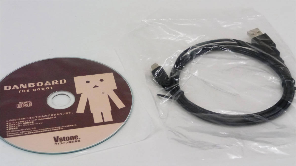
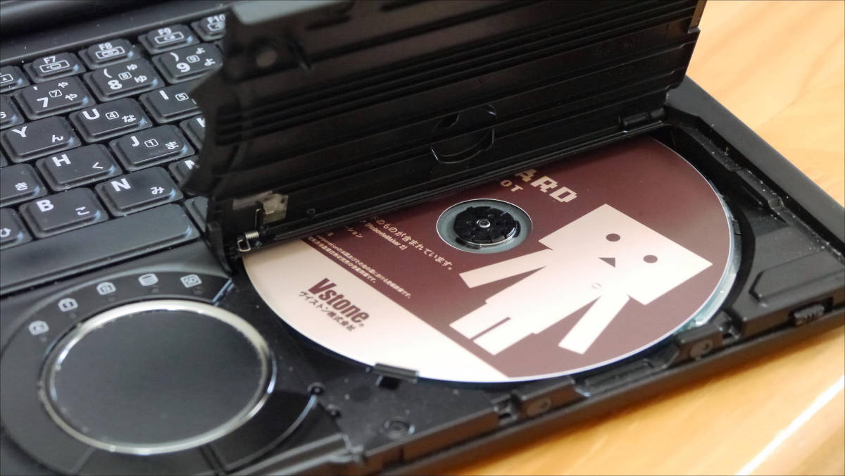
Here is a USB cable to connect the manual with Robo Danbo and manual. Assembly instructions are on DVD.
Opened another white box.
Metal parts are tightly packed.
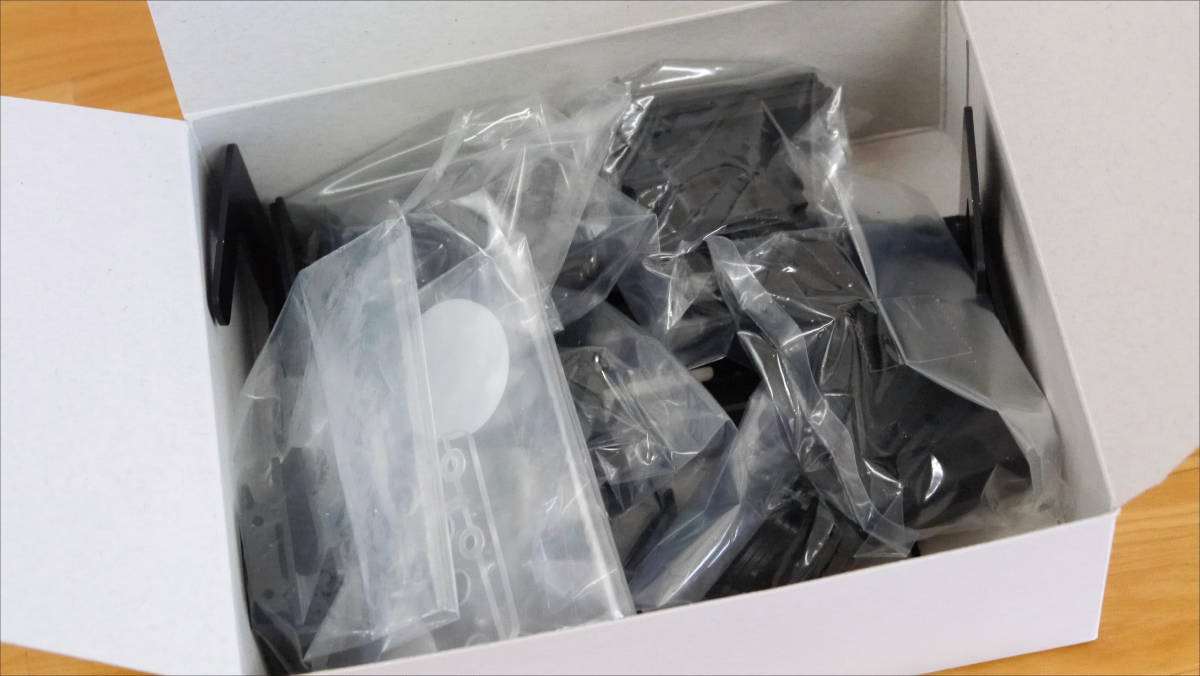
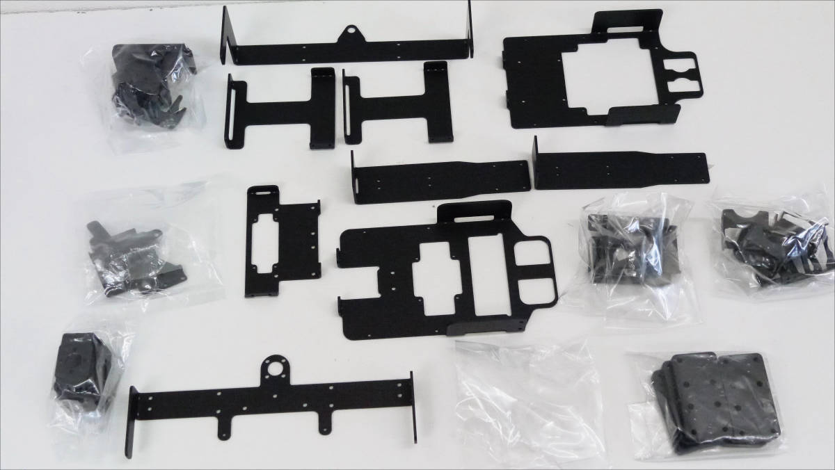
Taking out all this is like this.
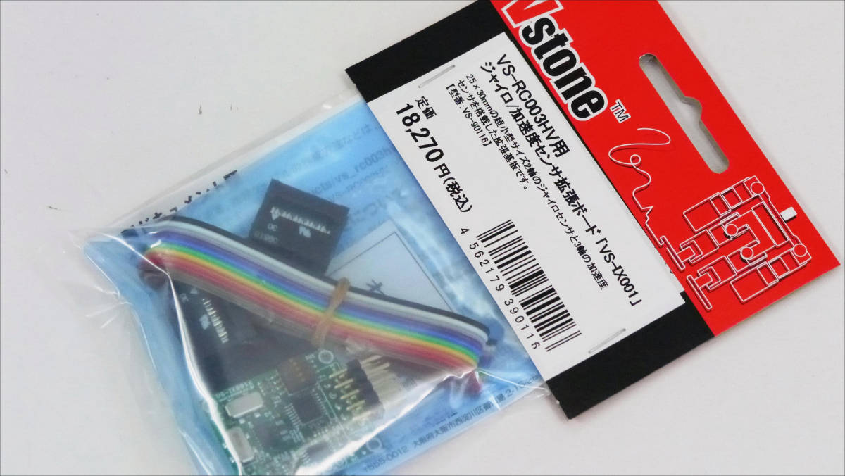
This is an optional item gyro / acceleration sensor "VS-IX001".
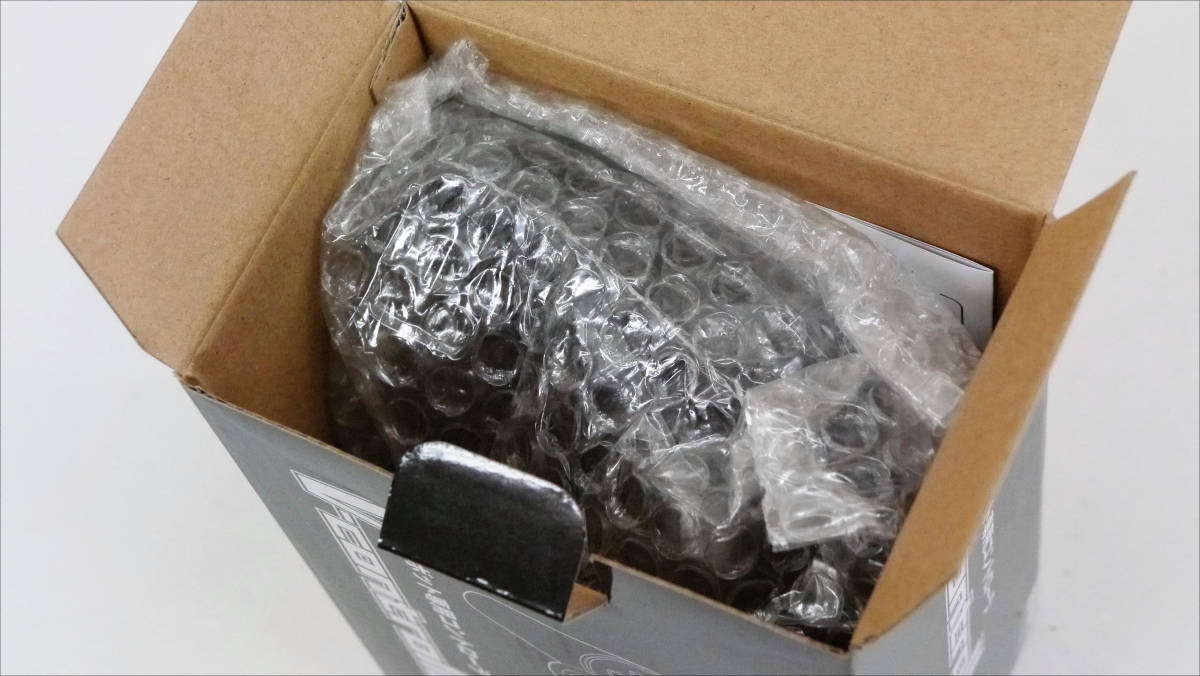
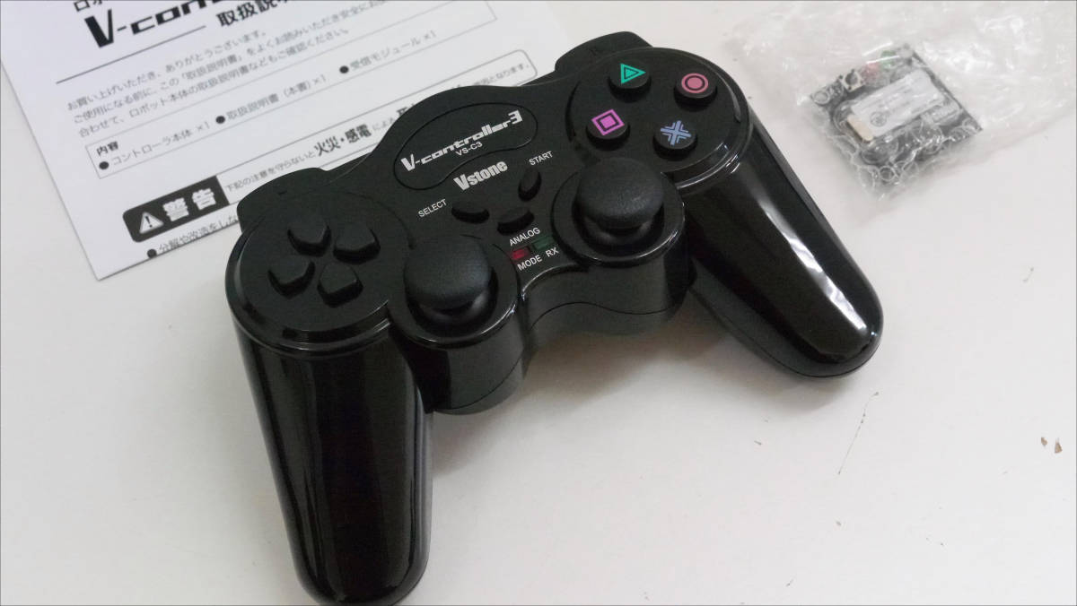
This is also an optional wireless controller "VS-C3".

When I opened the box ......
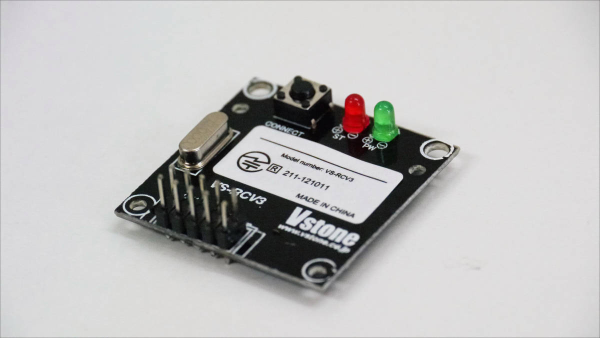
With the controller of a shape seen somewhere ... ...
There is a board.
◆ Assembly
Set the DVD to the PC, copy the RoboDambo Owner's Manual _ver1.00.pdf file, save it on the PC and open the manual file.
First of all, remove all servo tapping screws and servo horn for servo and store them. Be careful not to lose the servo horn and screws as they are used later.
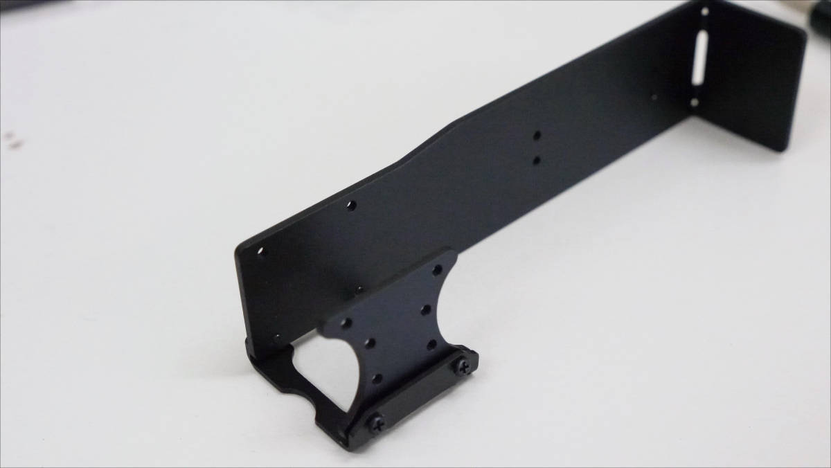
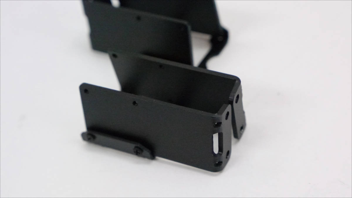
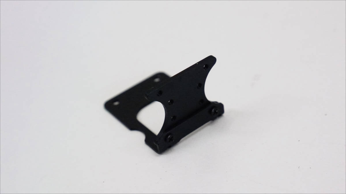
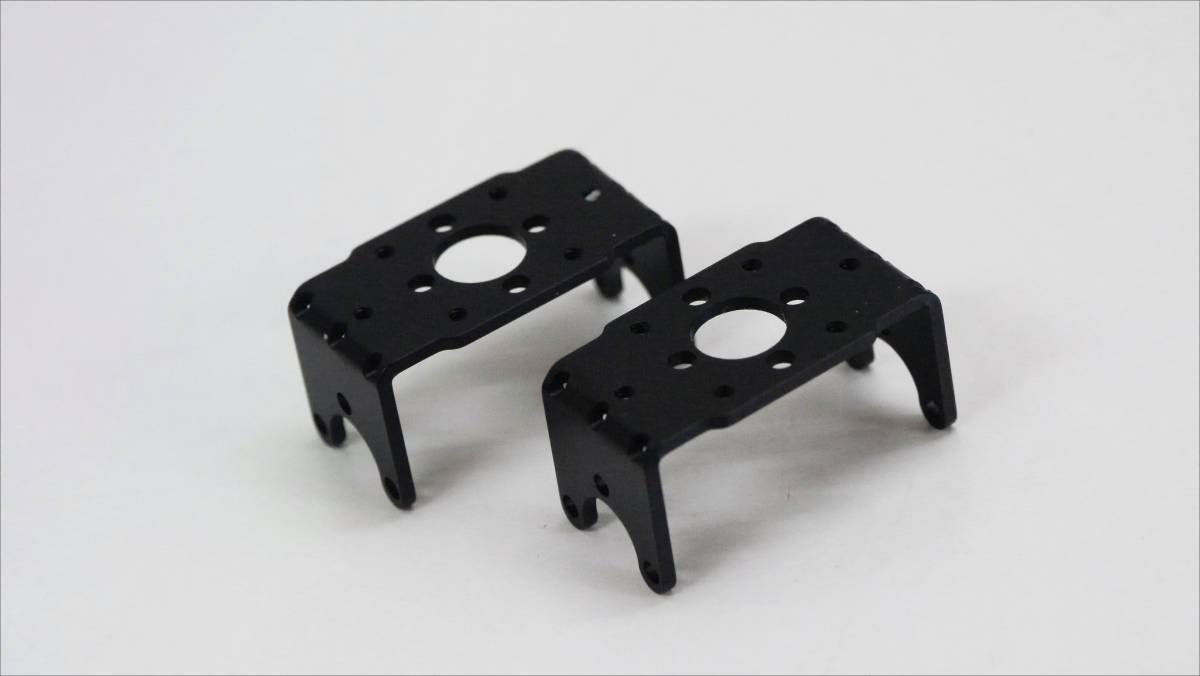
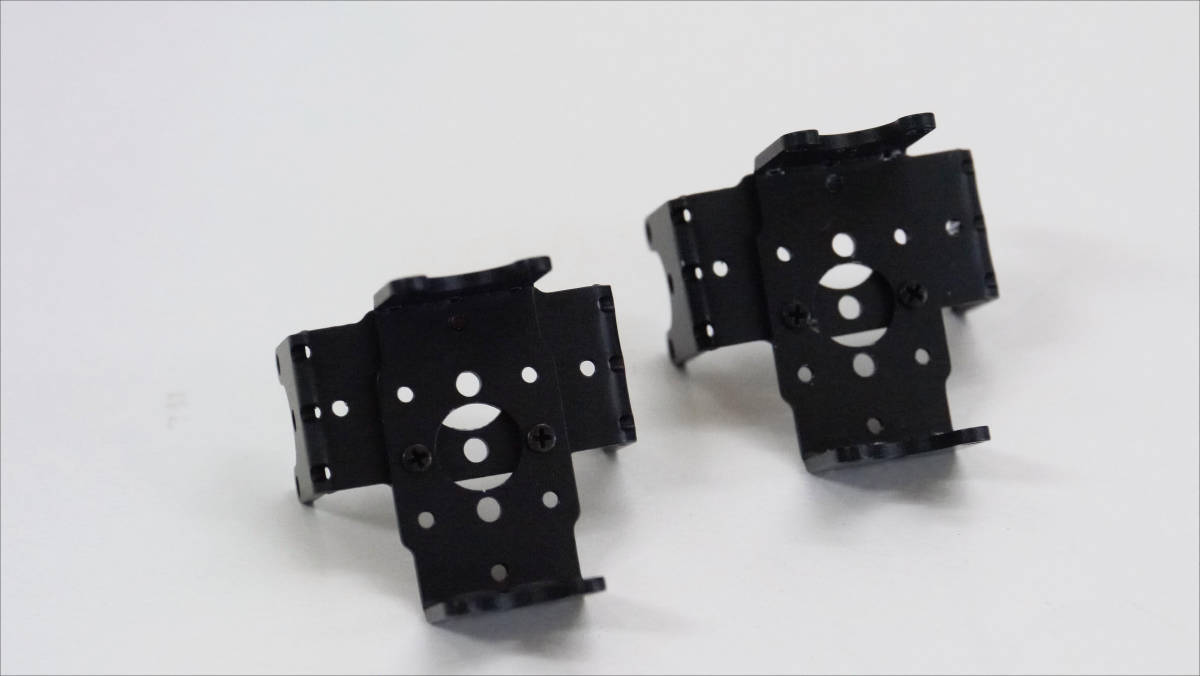
First of all, RobodanboarmWe will assemble from. This is a servo holder.
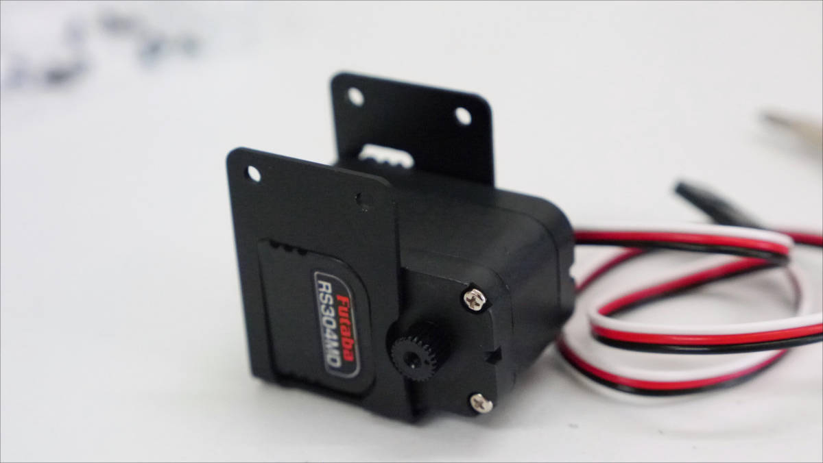
I will attach a servo to my arm.
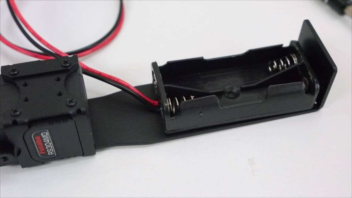
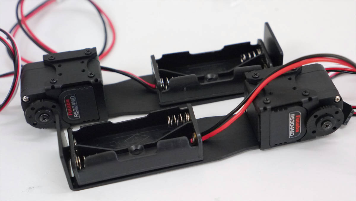
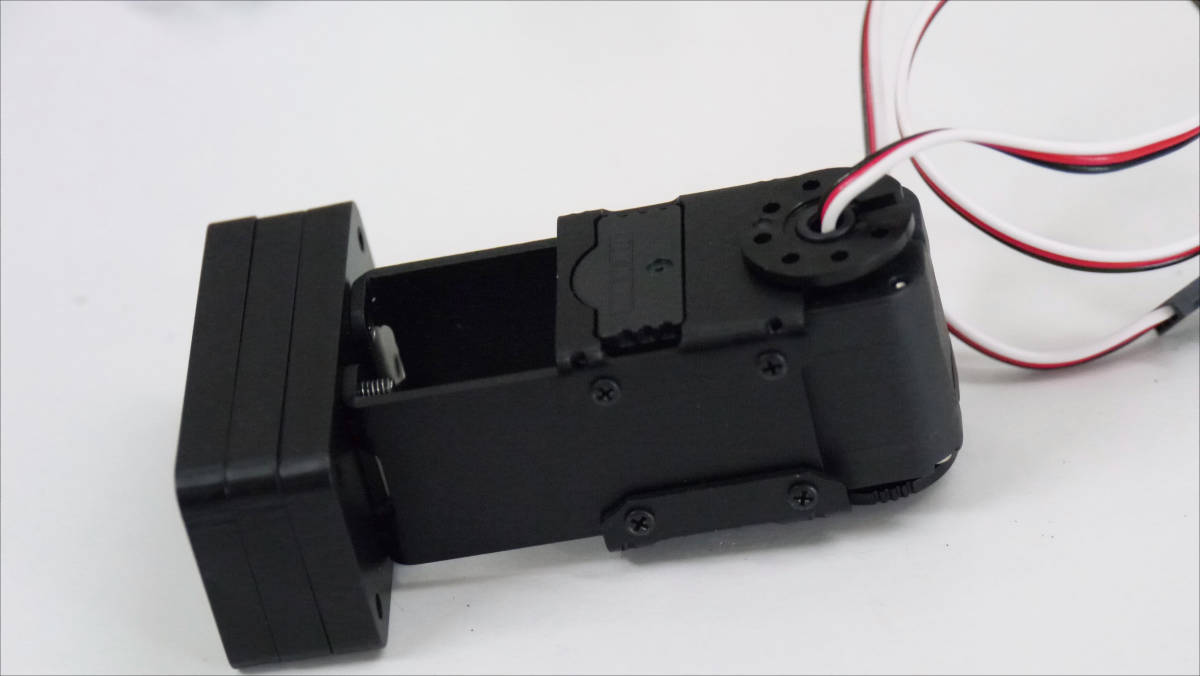
Battery holder installed. Apparently, Robo Dambo seems to be equipped with batteries in both arms.
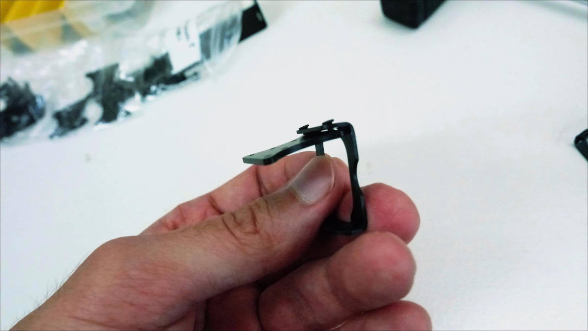
Servo horn removed before servo is attached. It is important to fit the notch of the servo and the circle of the axis together.
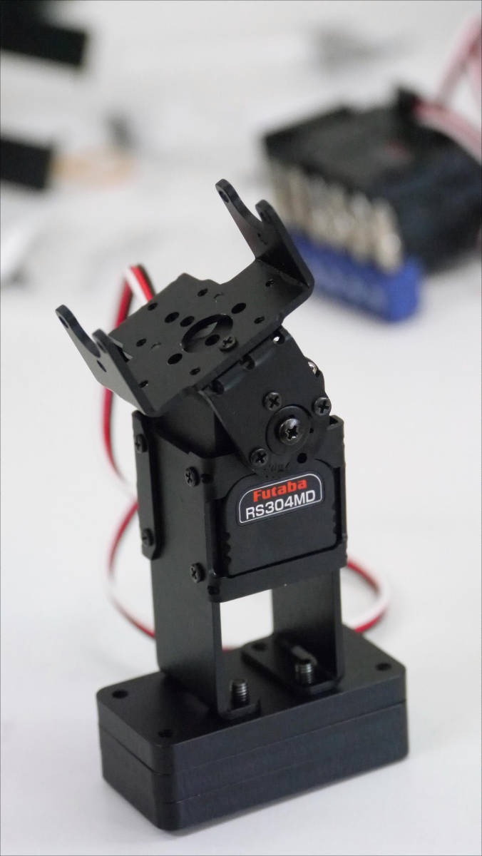
I will make two for both arms.
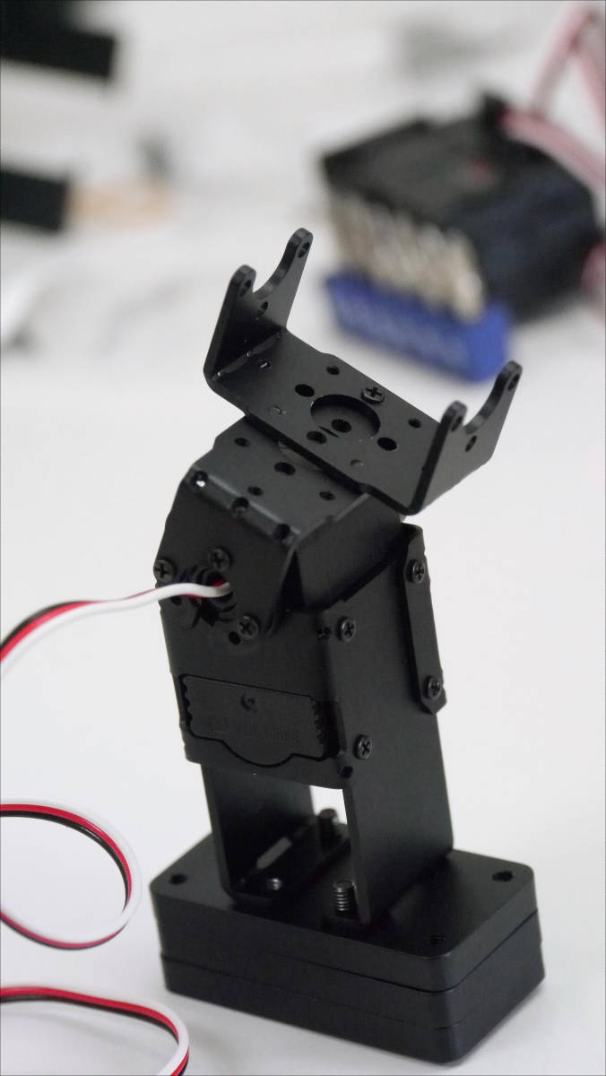
Next on Robo DambolegWe will continue to create.
Servo is attached to servo holder.
There are three weights on the bottom of the leg. This weight seems to ensure robustness of Robodanbo.
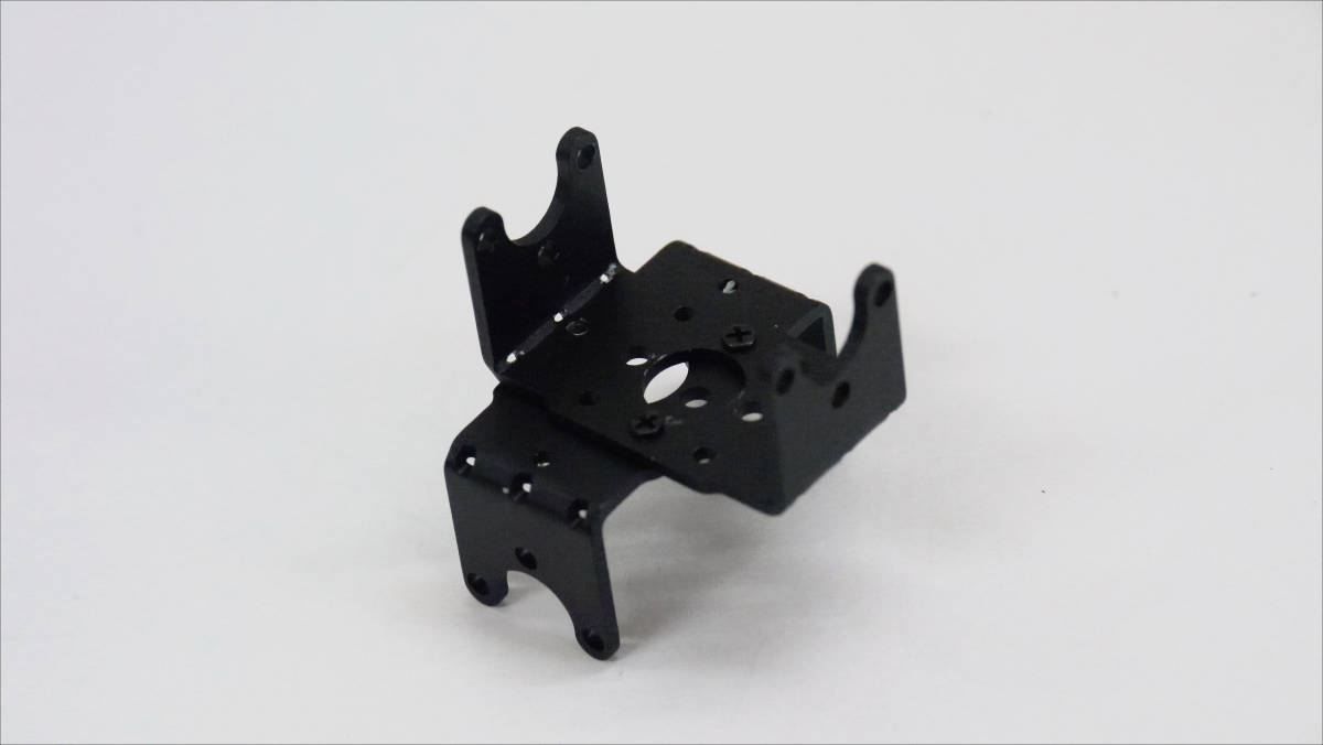
Next is RobodanboNeck part. To the metal parts here ......
Servo mounted.
I turned the direction and wore the second one.
I support it from the back with a stay.
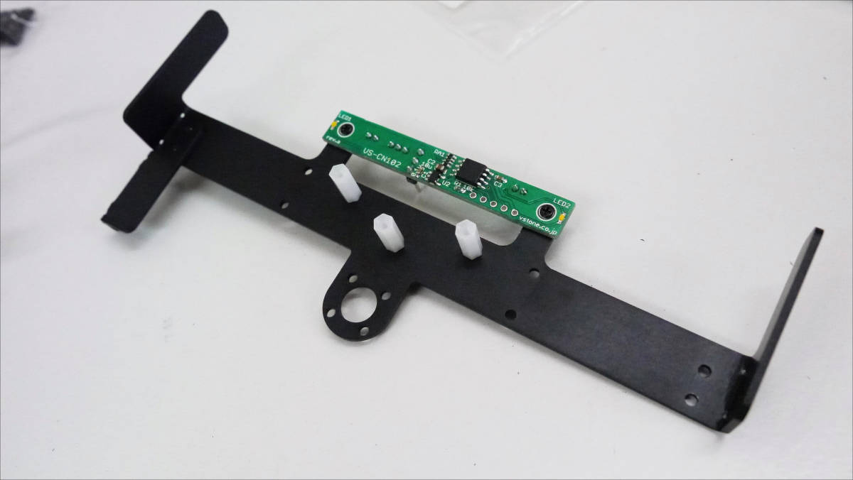
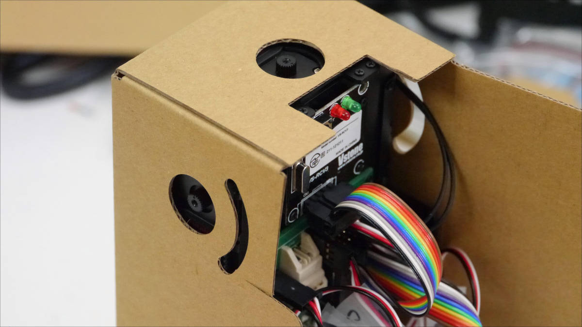
This is Dan BoHead part. Attach the LED · power supply board and white spacer. The spacer is fixed with screws of M2-3m, but it is easier to work by turning the spacer by hand without using a screwdriver because the screw is quite short.
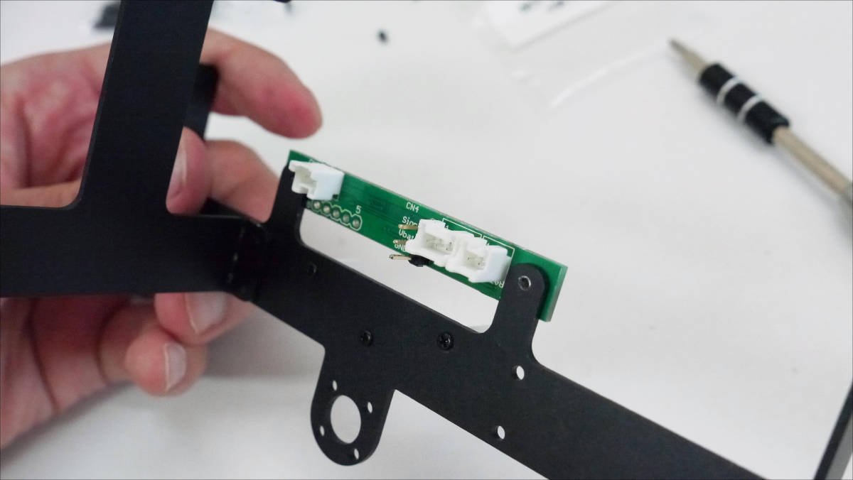
Various connectors on the back of the board.
I wear a stay ......
This completes the head part and the neck part. I can not imagine that this will be the face of Robodanbo.
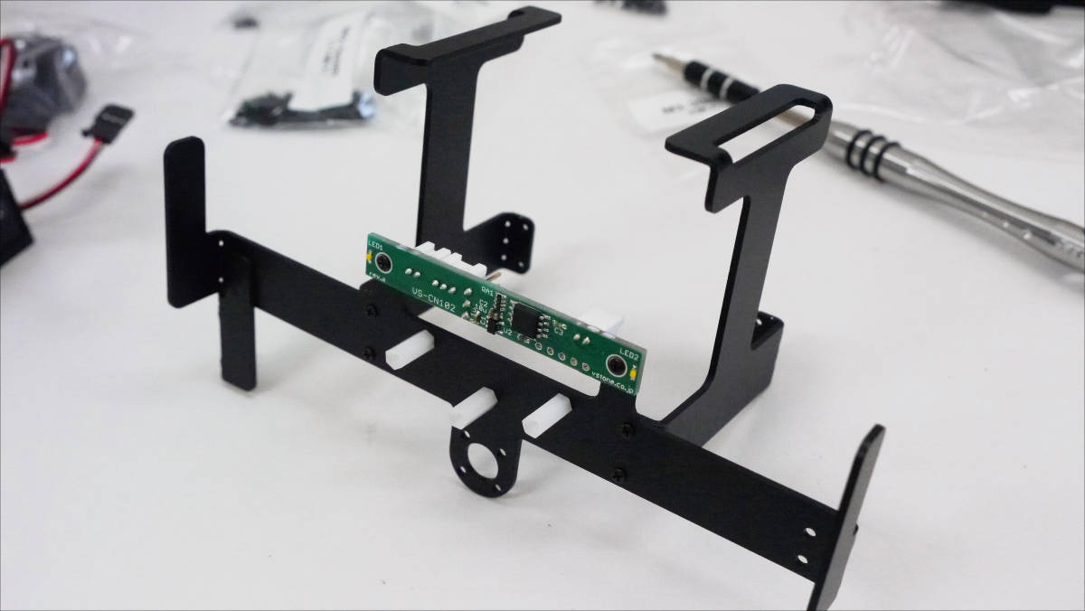
continuebodyI will make a part. First, install an optional gyro / acceleration sensor.
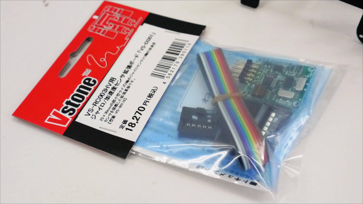
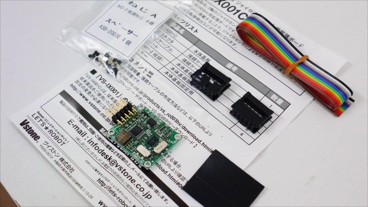
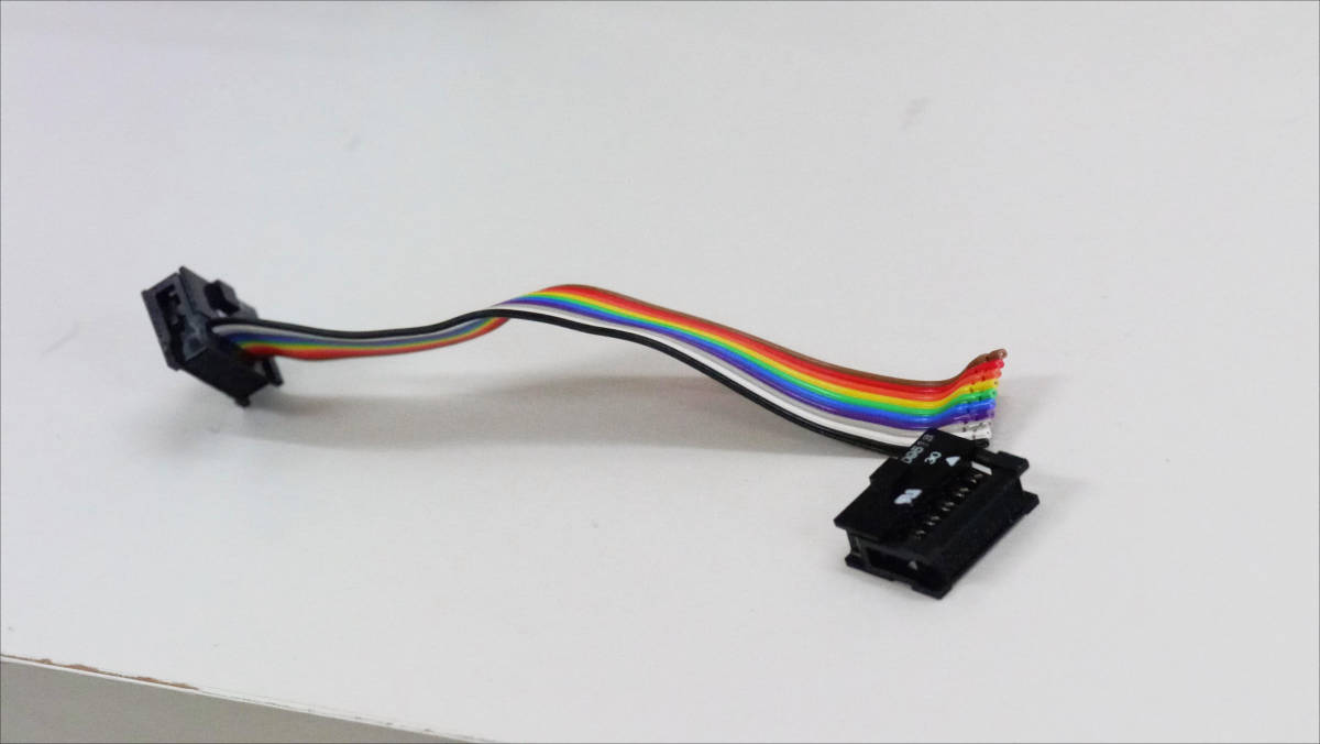
When opening the package, it contains the VS-IX100 main board, 10-core flat cable, 10-core connector, insulating sheet, screws.
Cut the four corners of the insulating sheet with scissors ......
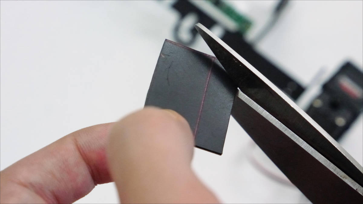
Paste it on the back of the main board.
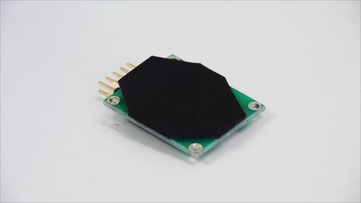
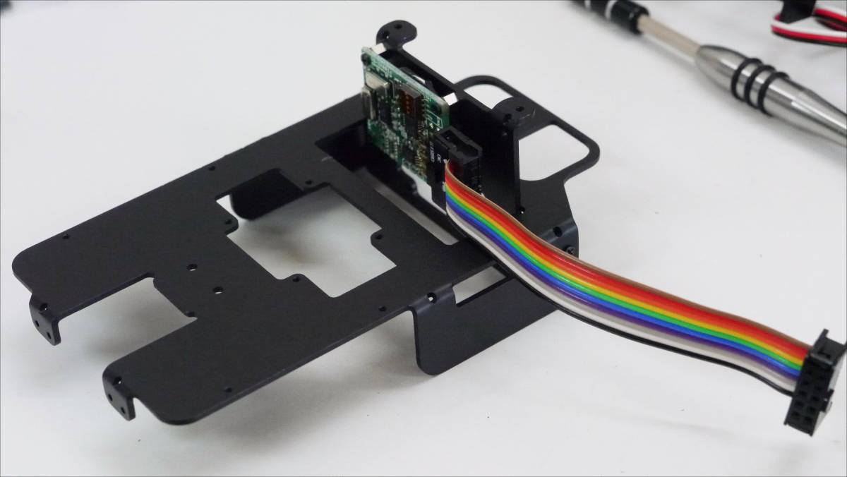
After insulation processing, fix gyro / acceleration sensor to stay.
Here crimp the connector to the 10-core flat cable. Cut the cable at 100 mm according to the instructions ... ...
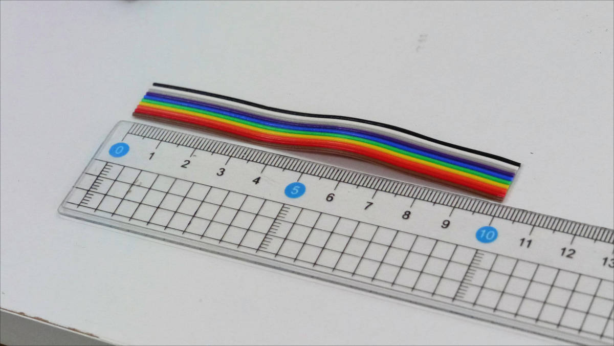
Crimping completed.
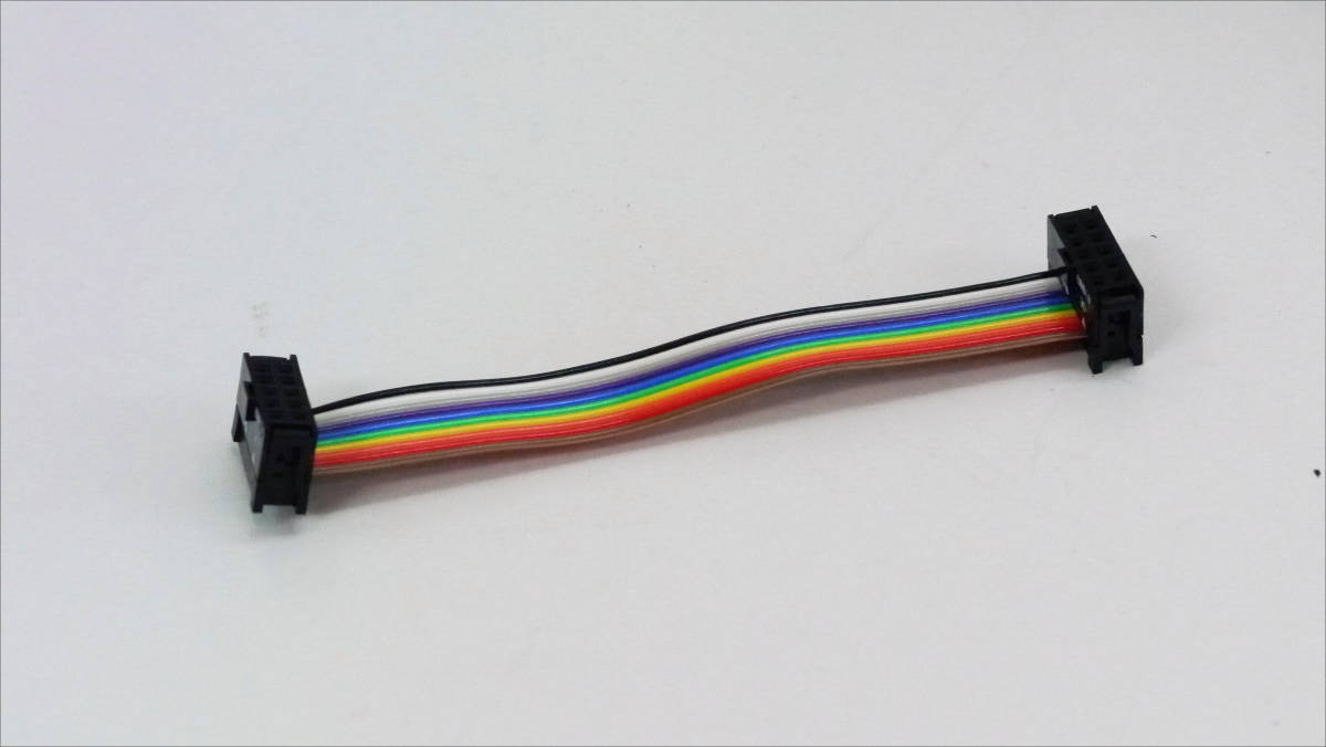
I installed a 10 core flat cable ......
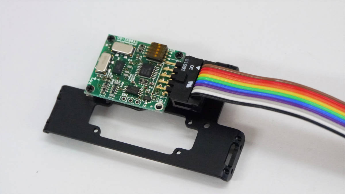
A gyro / acceleration sensor was built in the front of the fuselage.
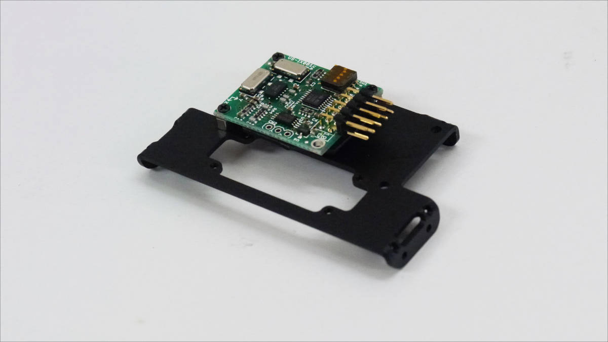
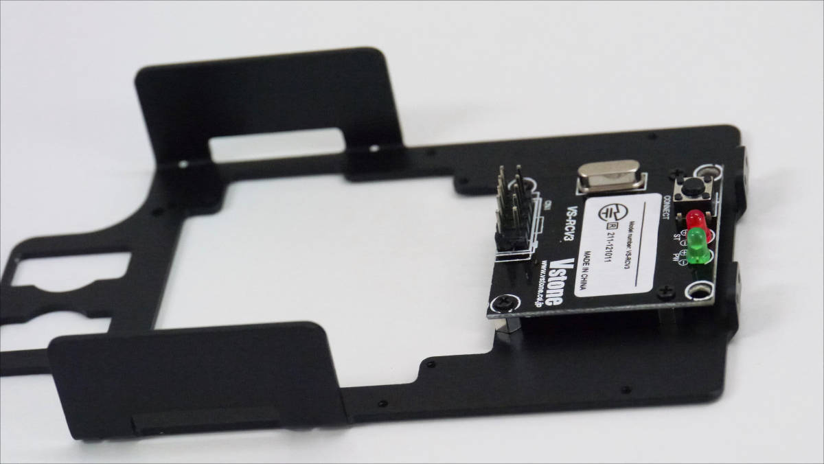
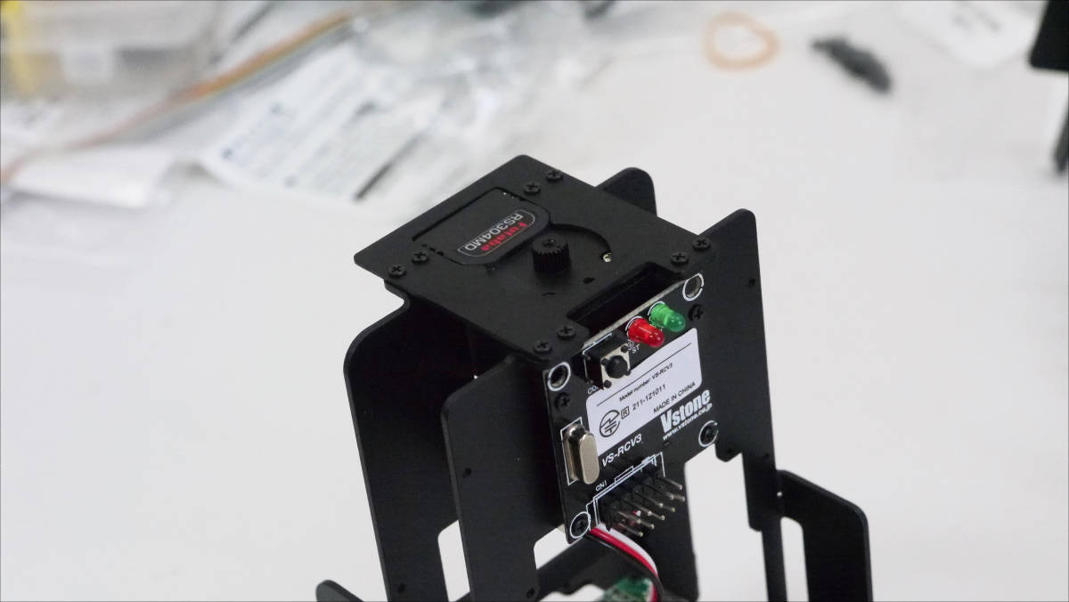
Next, install the VS - C3 reception module.
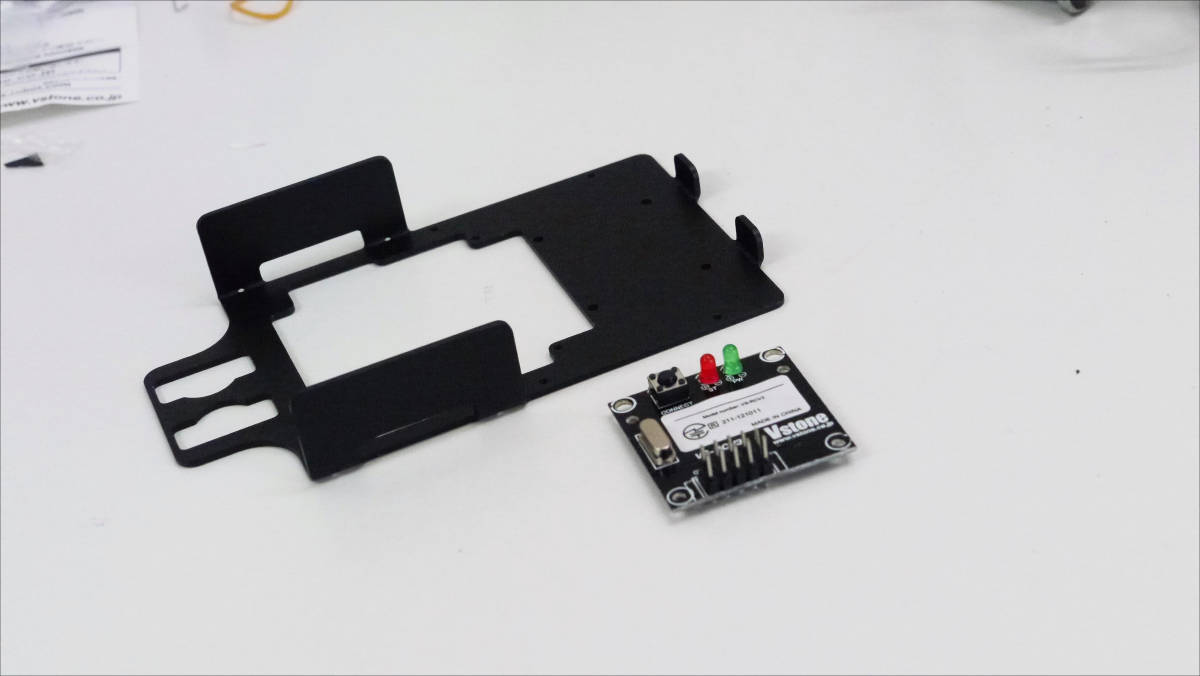
Attach a spacer to the back of the VS-C3 reception module ......
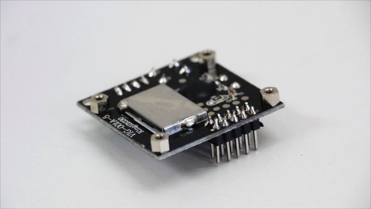
The VS - C3 reception module was installed at the rear of the fuselage.
Two servos installed ......
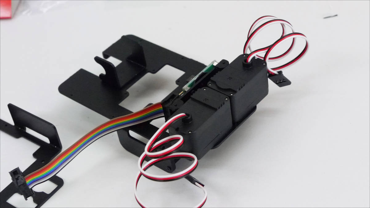
Combine the front of the fuselage and the rear of the fuselage.
Pass the servo cable through the hole in the rear of the fuselage ......
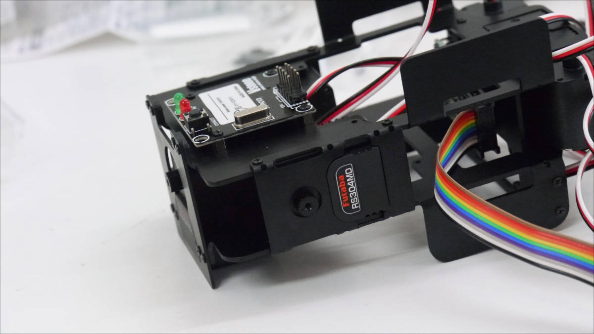
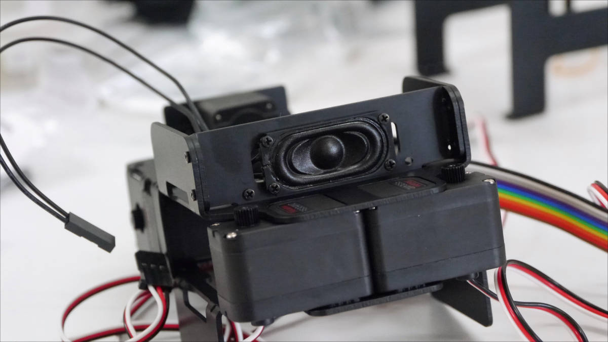
Servo is mounted on the top. This will be the neck part.
We also mounted servos on the left and right sides.
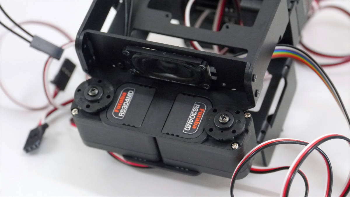
Pass the speaker cable through the hole in the center of the photo ......
I installed a speaker.
Next I will create a leg joint.
The metal parts are set like this.
I will make two.
Prepare both feet parts I made previously.
After setting in the free horn on the back of the servo ......
I will install metal parts.
To the servo of the body part ... ....
I wore my legs.
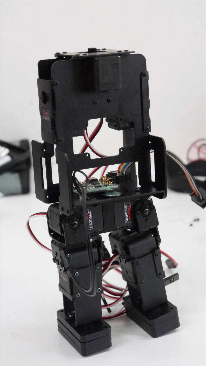
Robo Dambo stood.
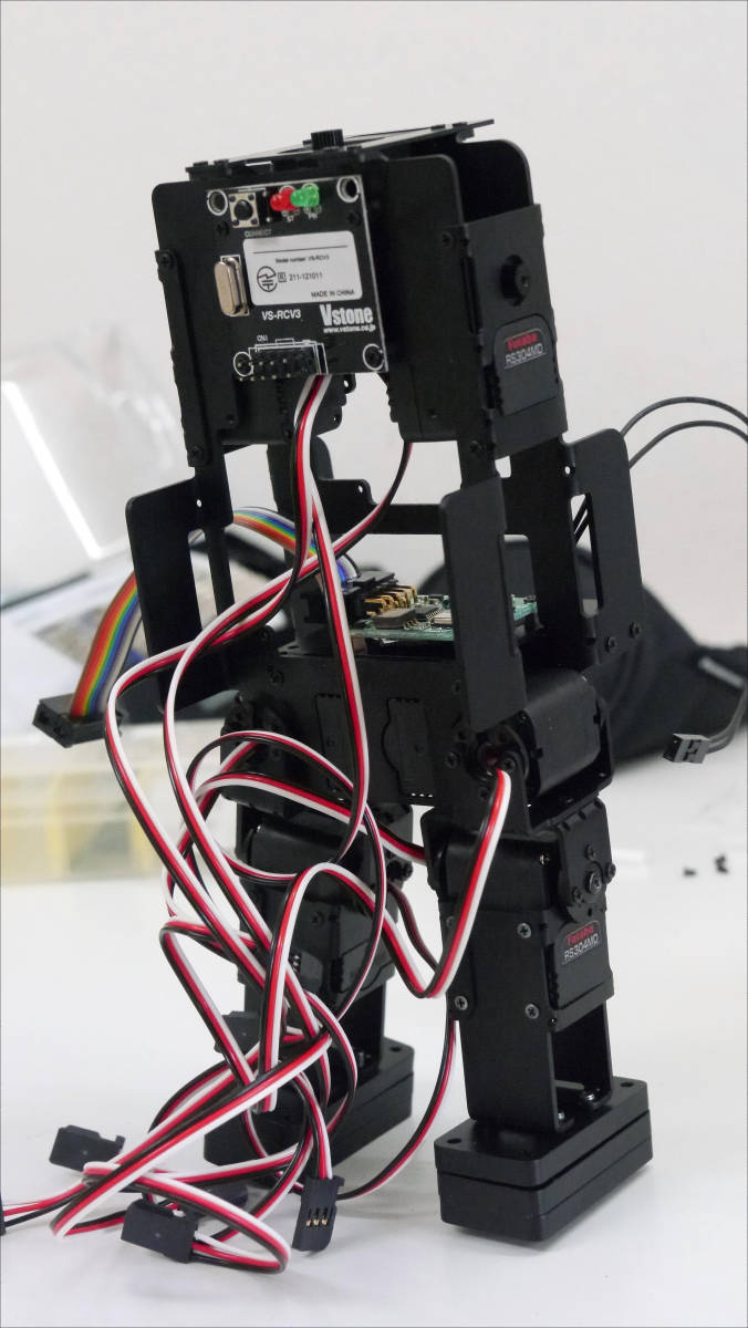
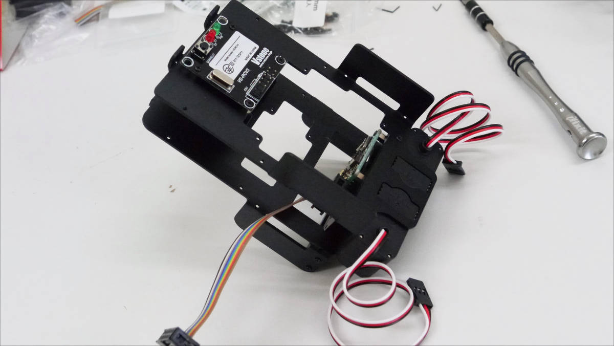
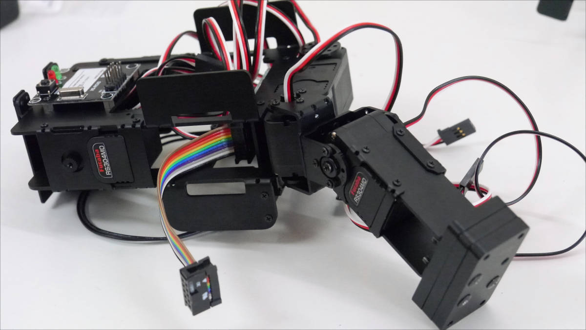
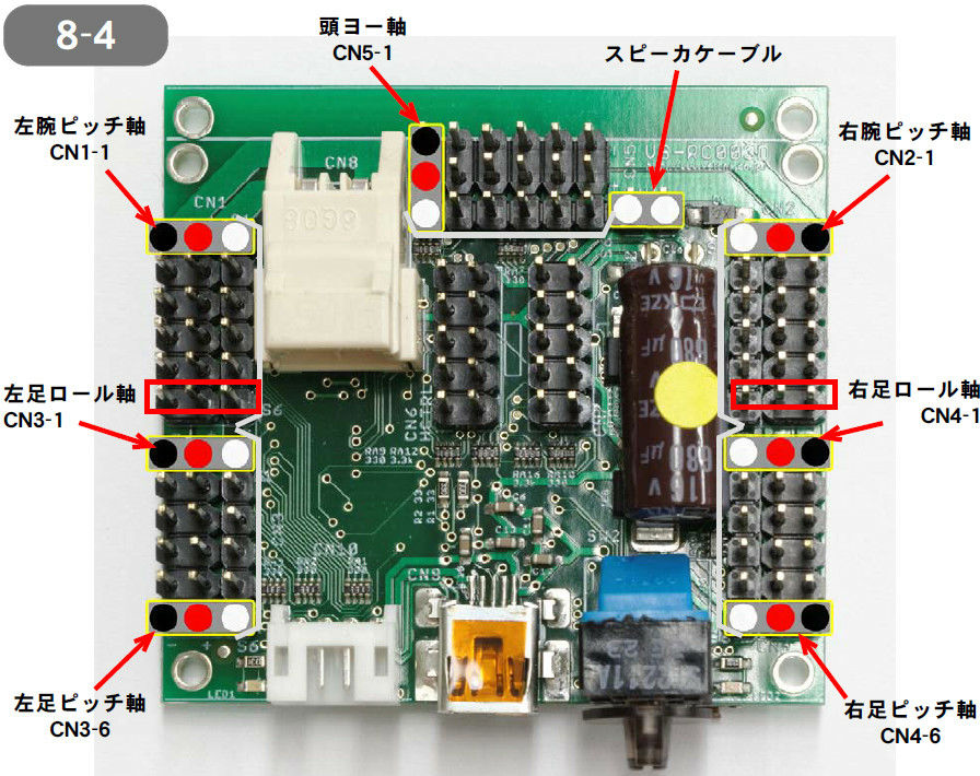
Next, I attach the CPU board to the fuselage and wire it.
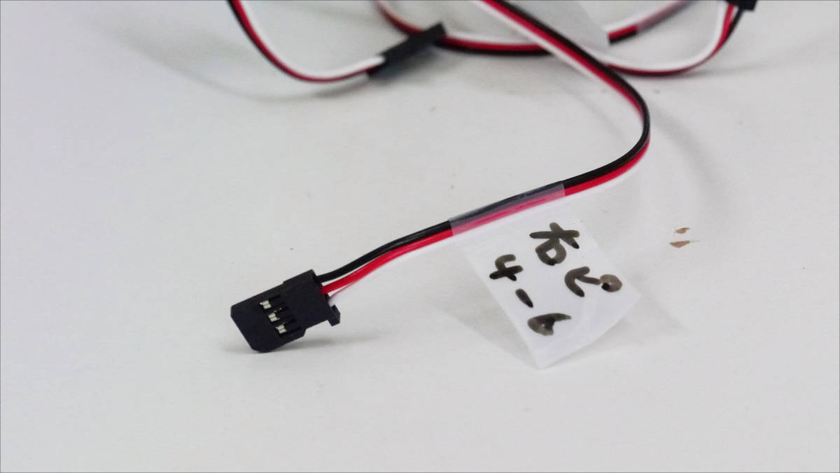
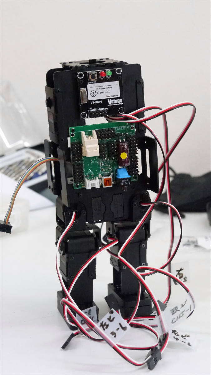
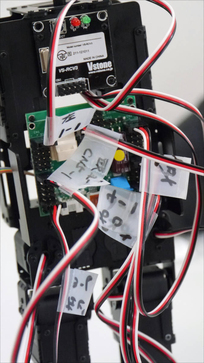
First of all, mark all servo cables as preparation. This is the sign "Servo CN4-6 for right leg pitch".
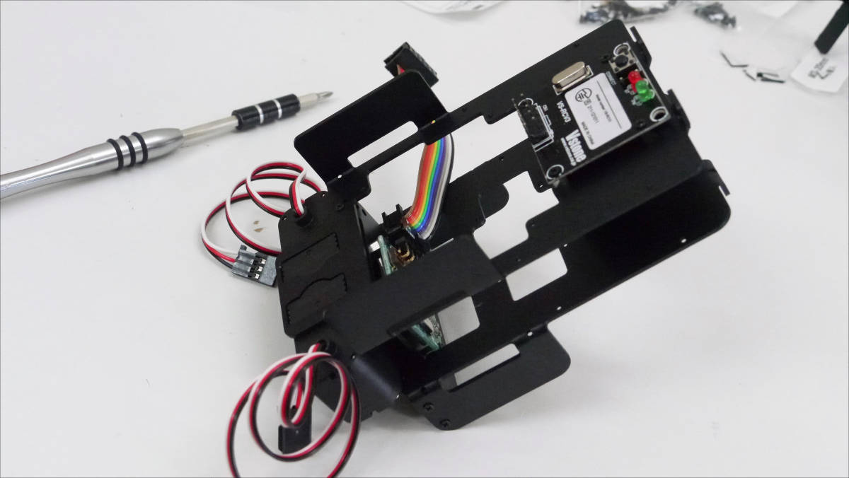
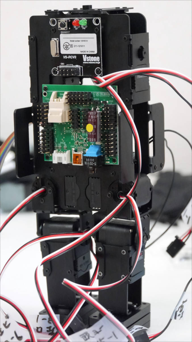
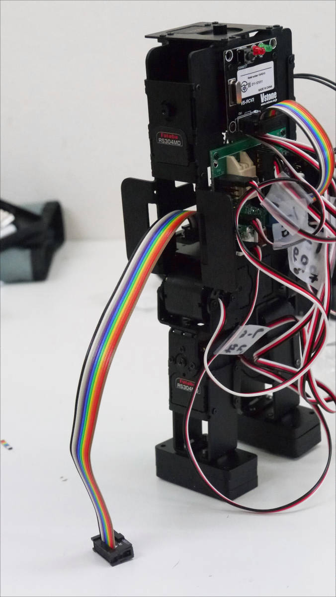
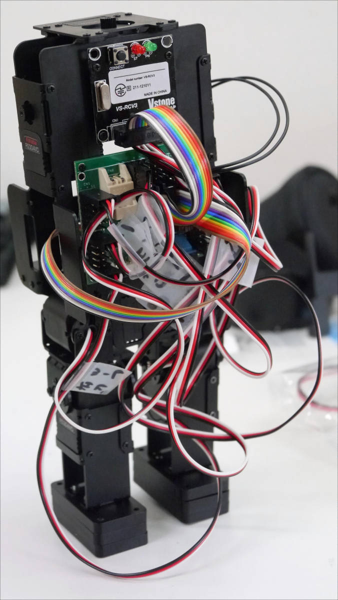
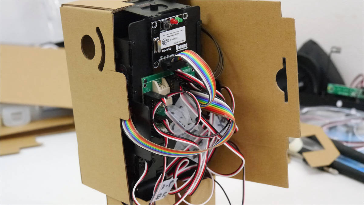
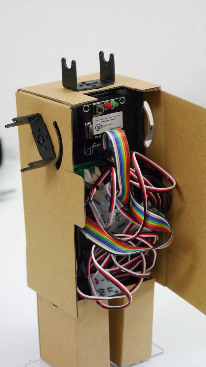
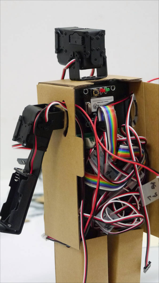
The CPU board is mounted in the center of the body. Incidentally this is the back of Robodanbo.
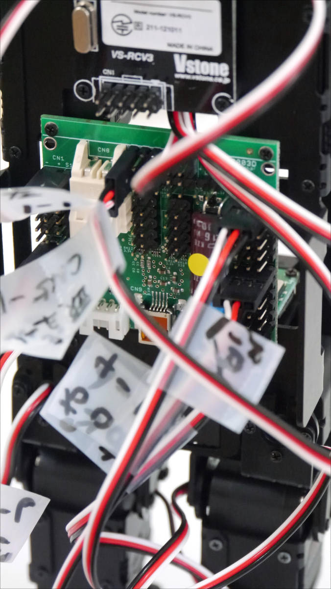
Route the servo cable, gyro / acceleration sensor cable, VS - C3 receiving module to the jumper pins of the CPU board.
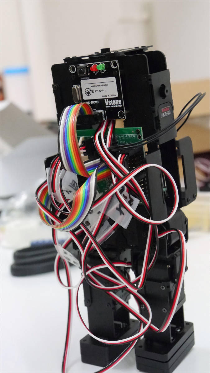
Here we found out that the length of the gyro / acceleration sensor cable is insufficient, and to remake ... .... There was 100 mm in the instructions, but it was better to keep it around 200 mm. When removing the connector, it is necessary to remove it carefully so as not to break the claws on both sides.
Again, create a 10-core flat cable at 200 mm.
I got to the specified jumper pin well.
at lastExteriorWe will begin.
This isExterior of legsportion.
Secure with double-sided tape.
Two pairs completed.
I will put it on Robodanbo.
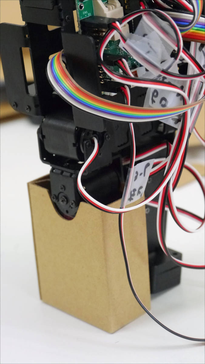
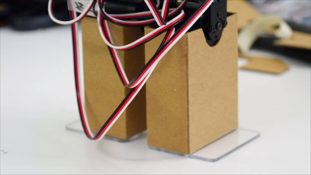
A transparent plate is attached to the soles of the feet.
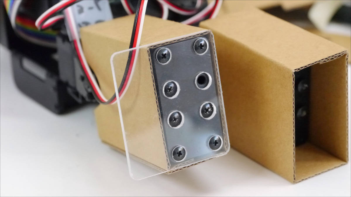
The stability has improved.
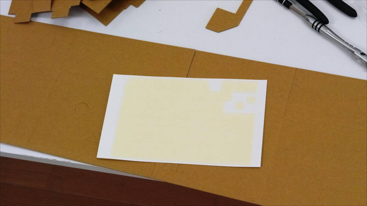
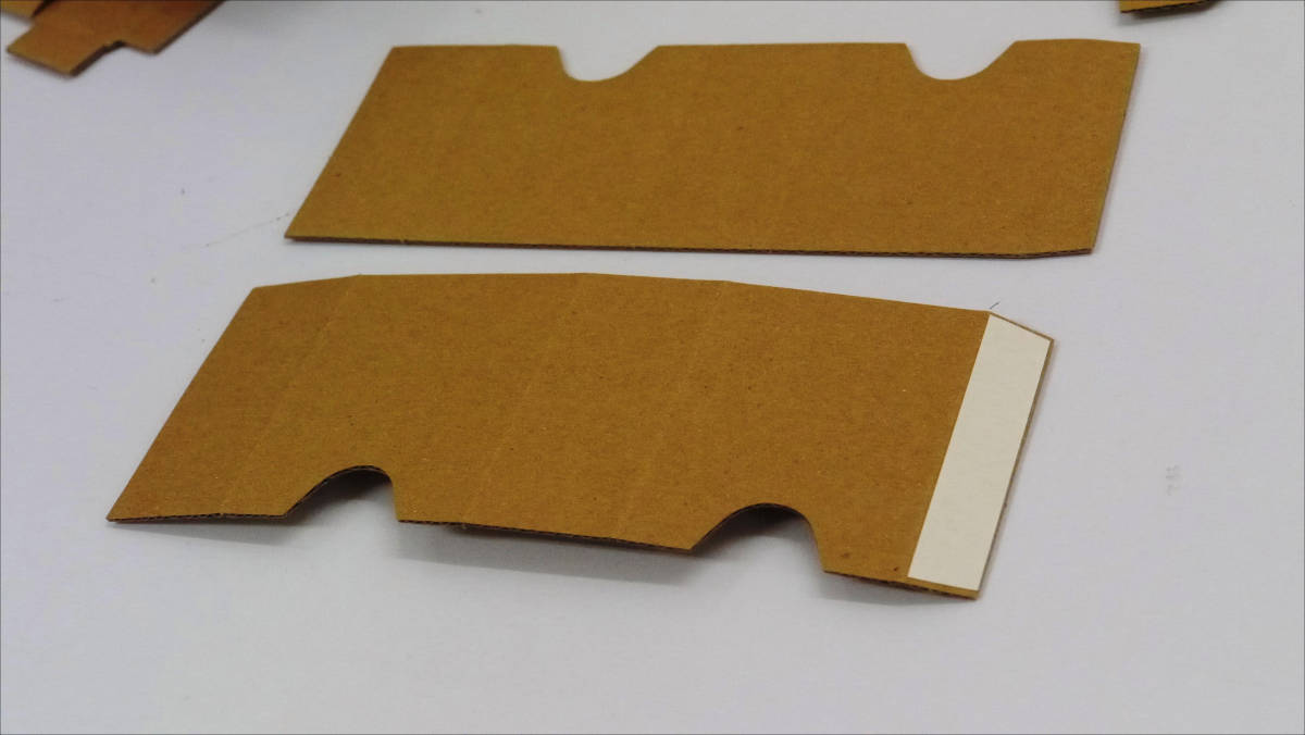
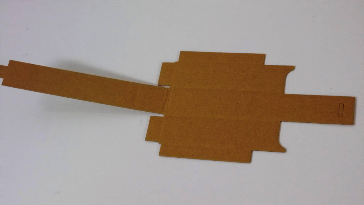
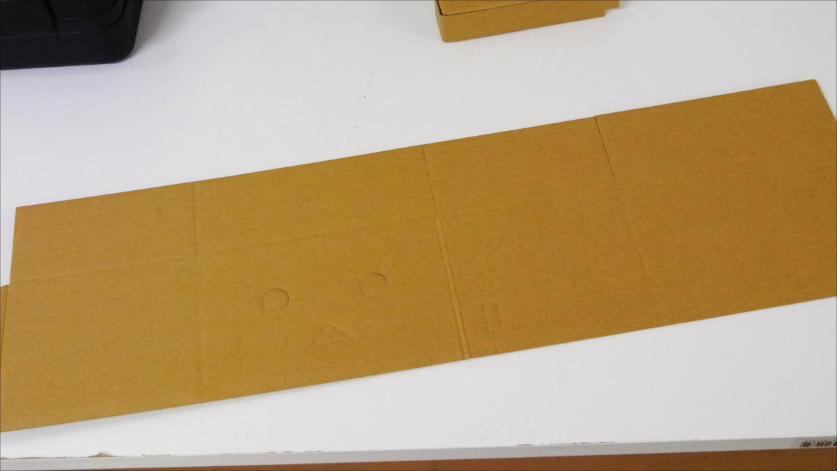
this isExterior of the body partparts.
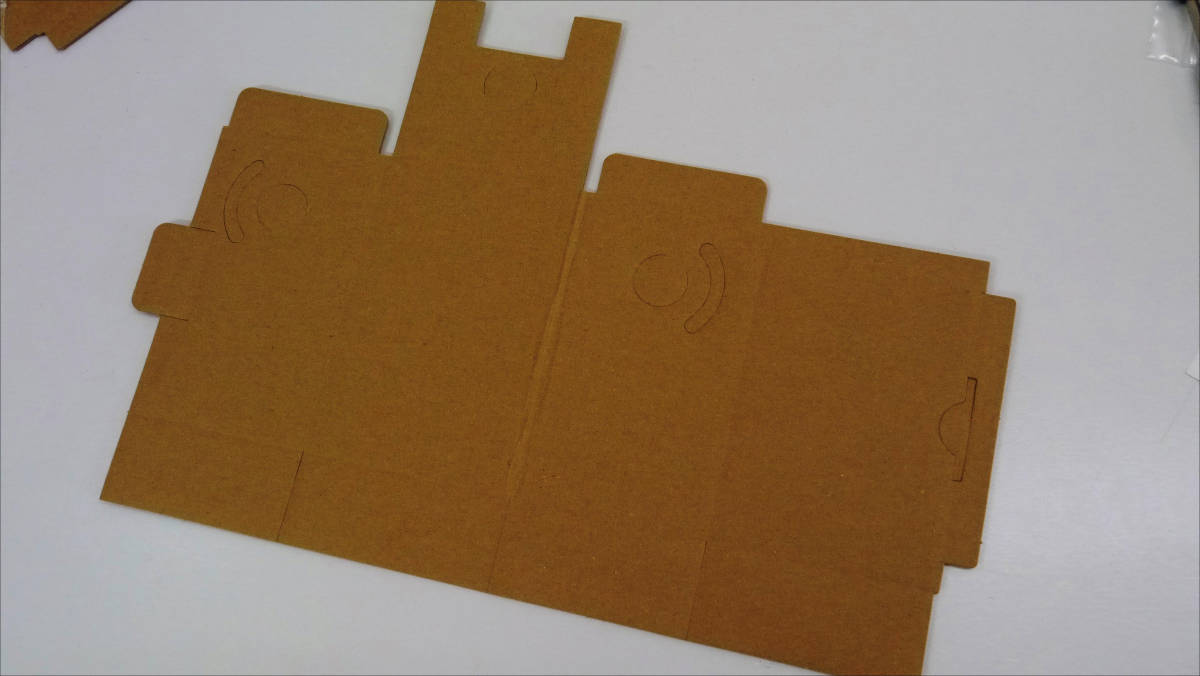
I punctured the hole.
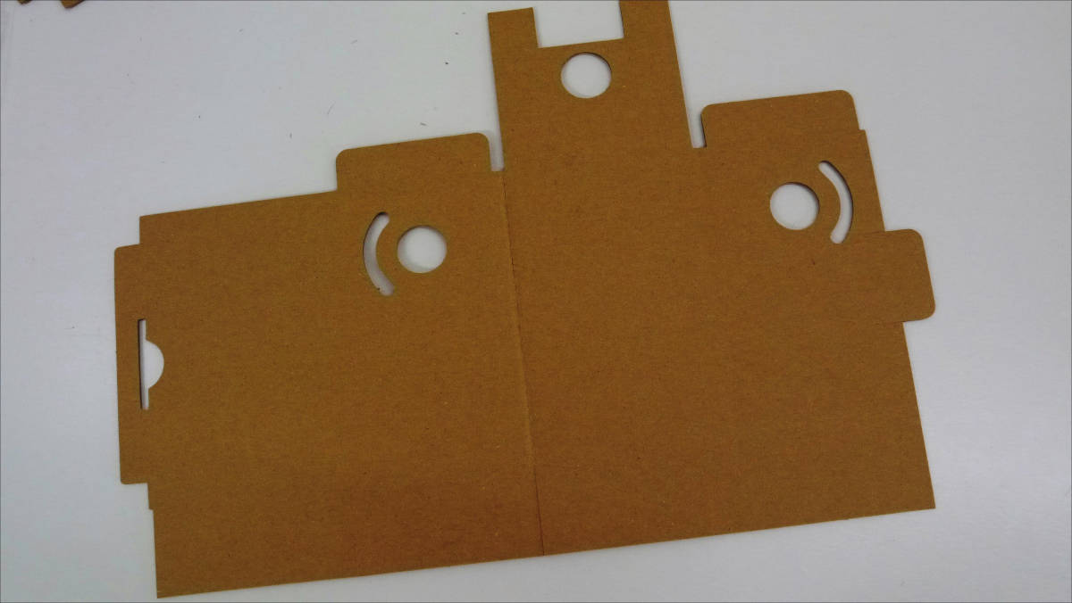
Paste double sided tape ...
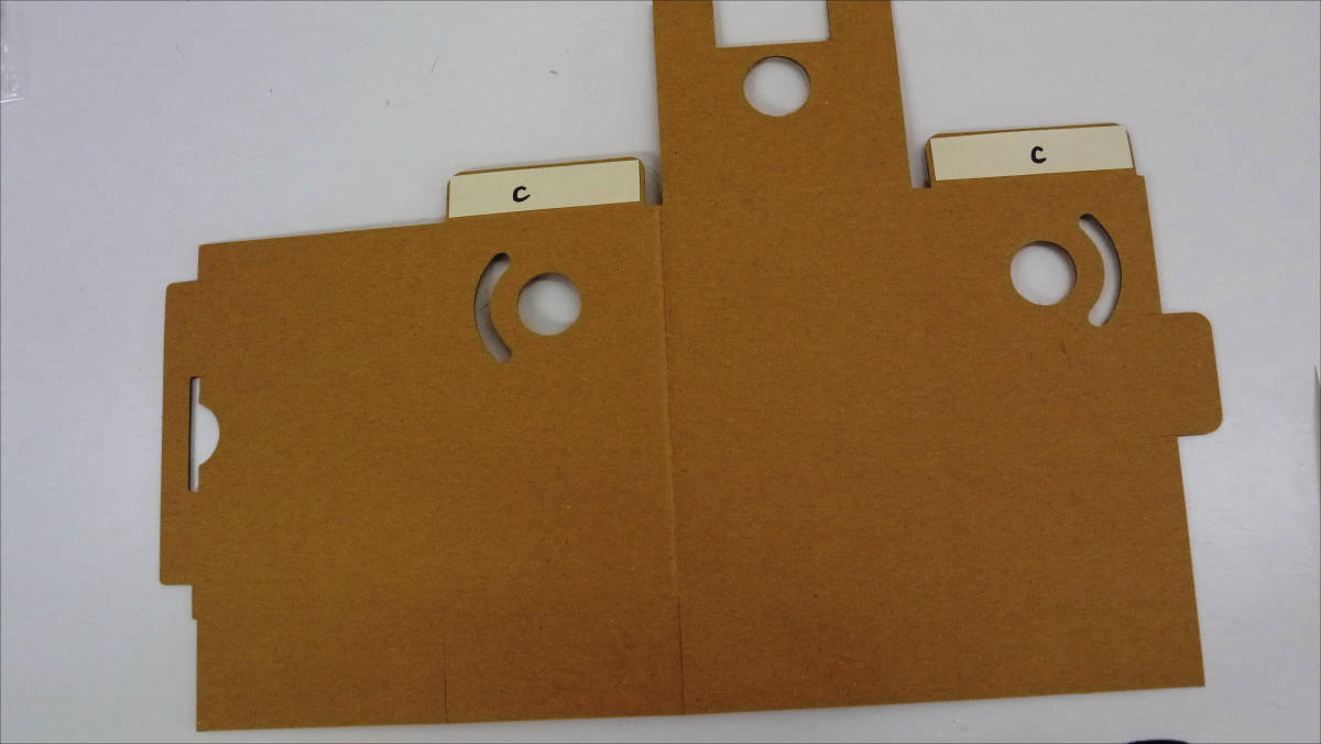
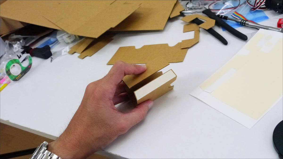
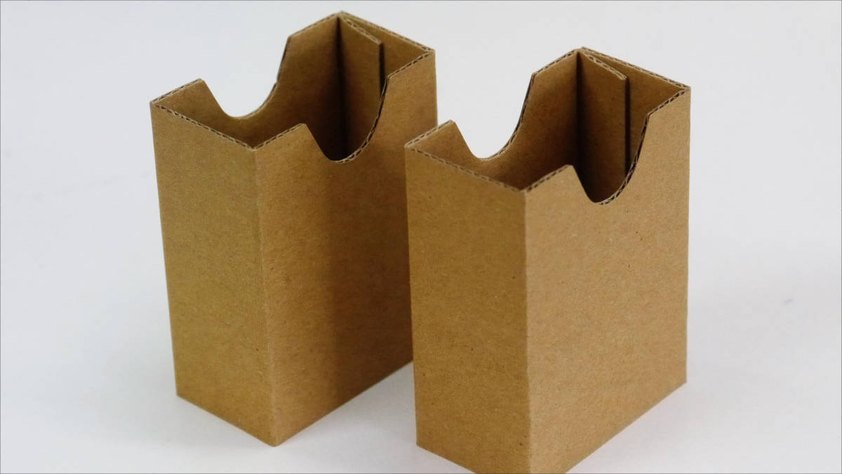
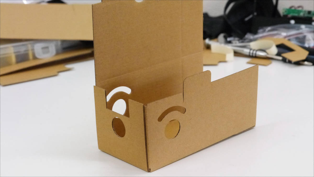
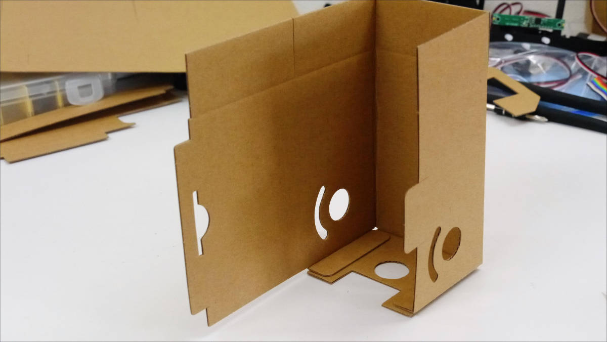
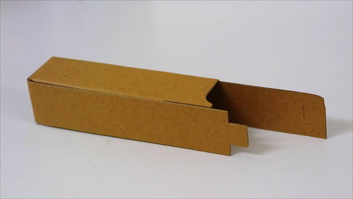
Assemble it into a box.
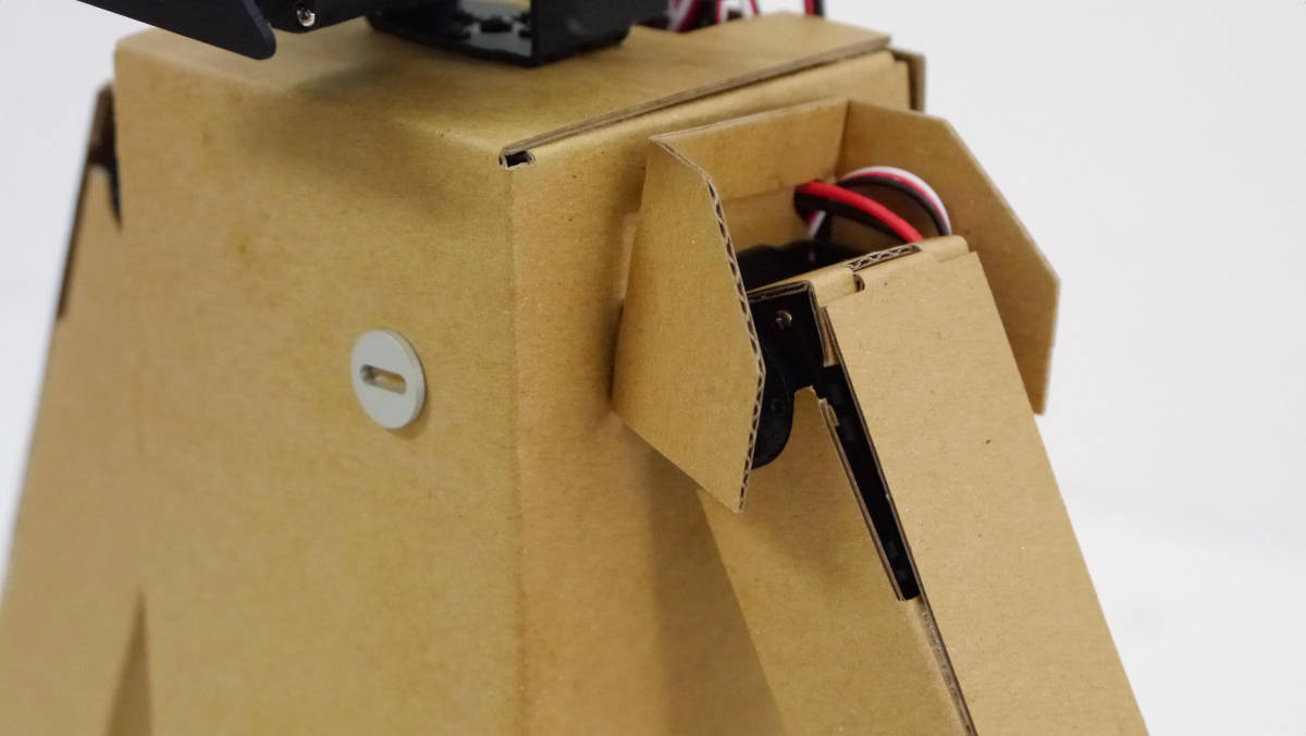
The assembled box is carefully attached from the front of the fuselage.
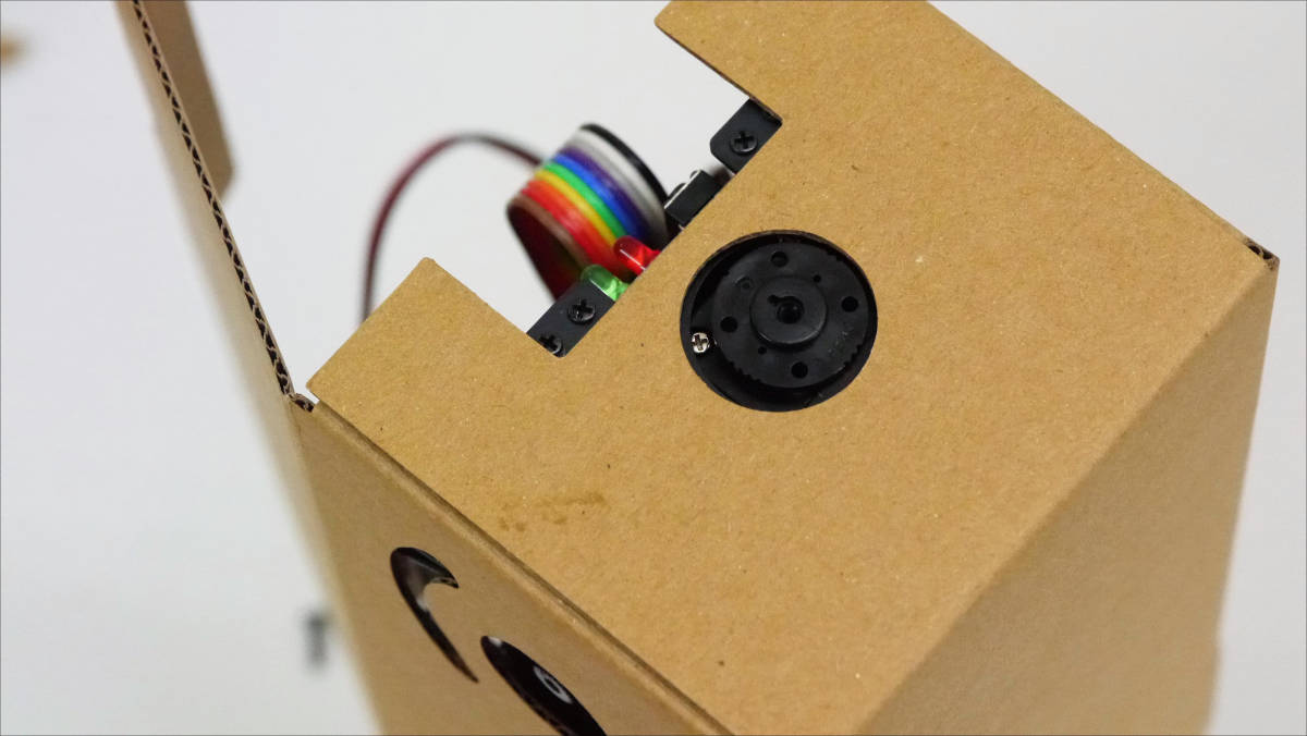
Adjust so that the servo horn can be seen firmly.
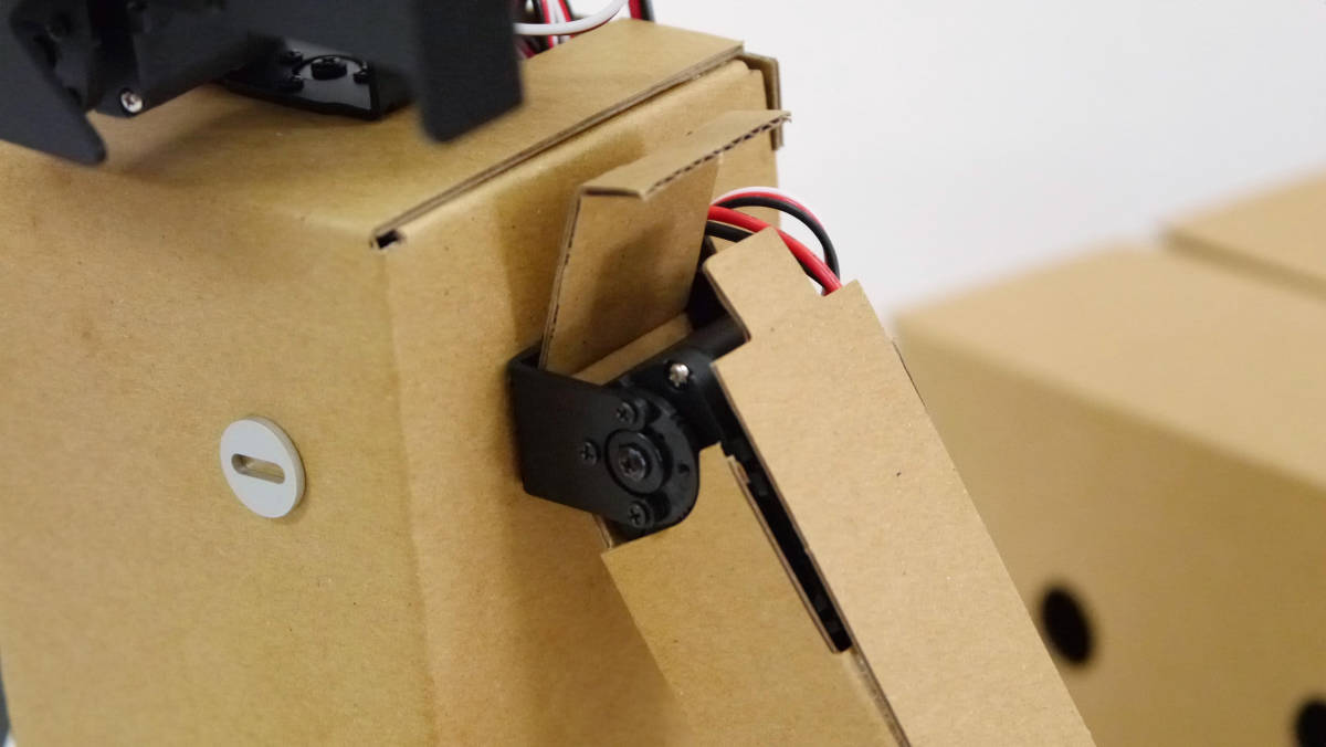
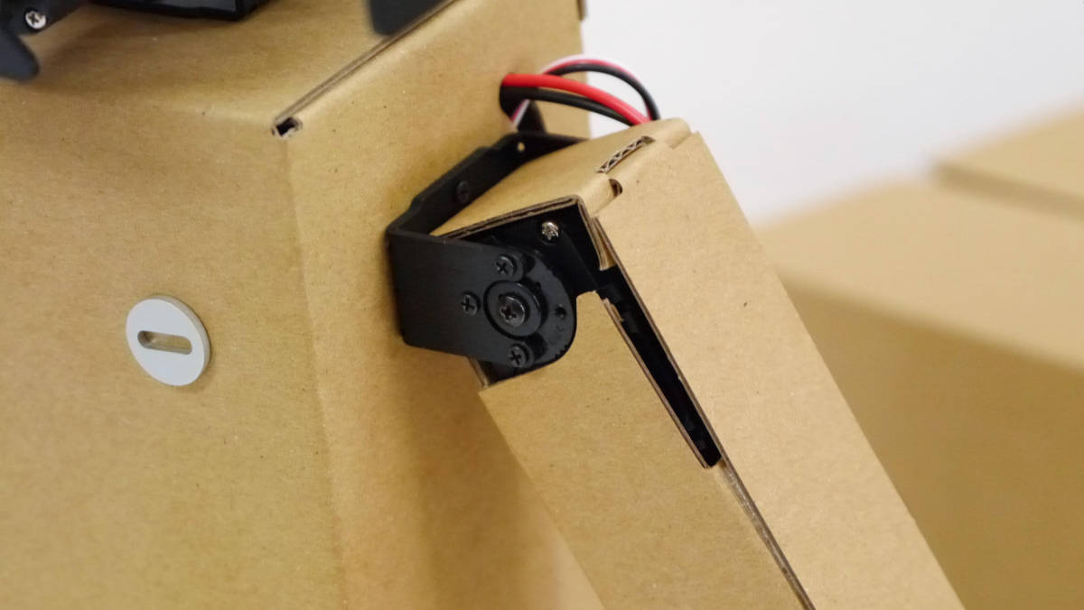
Bracket attached to servo.
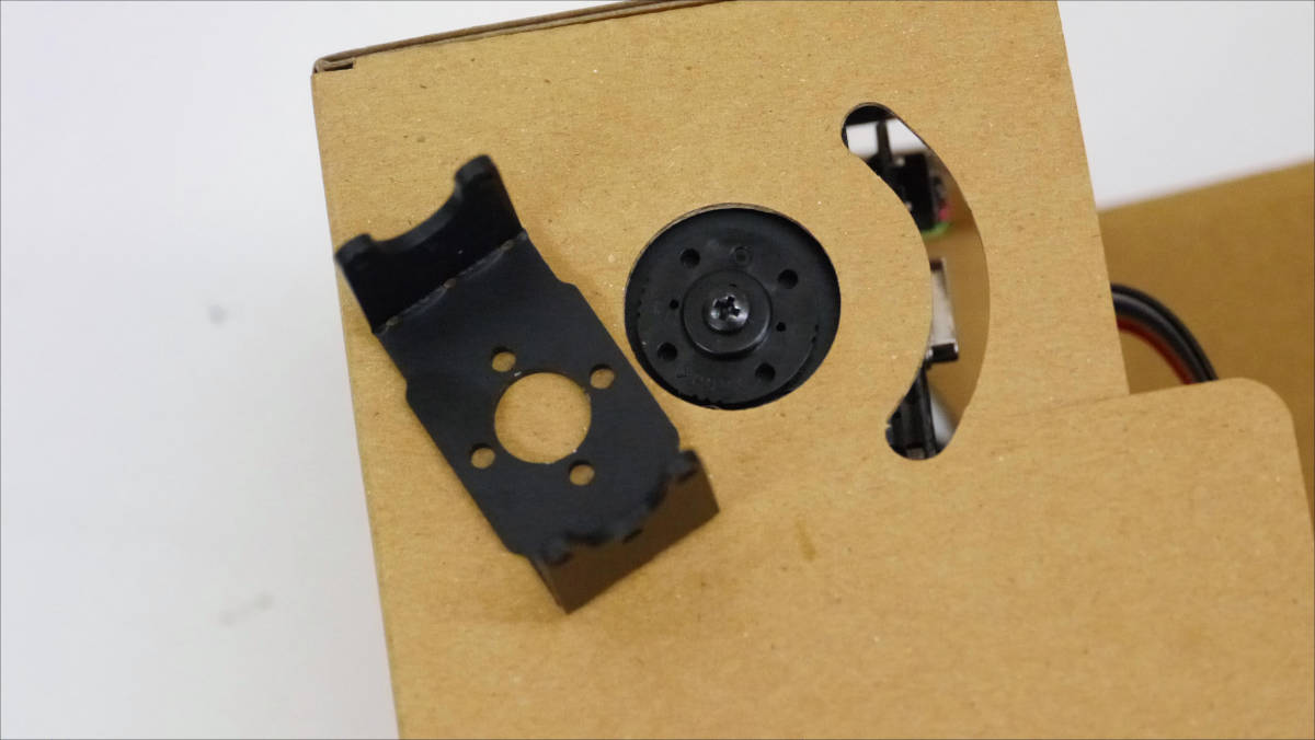
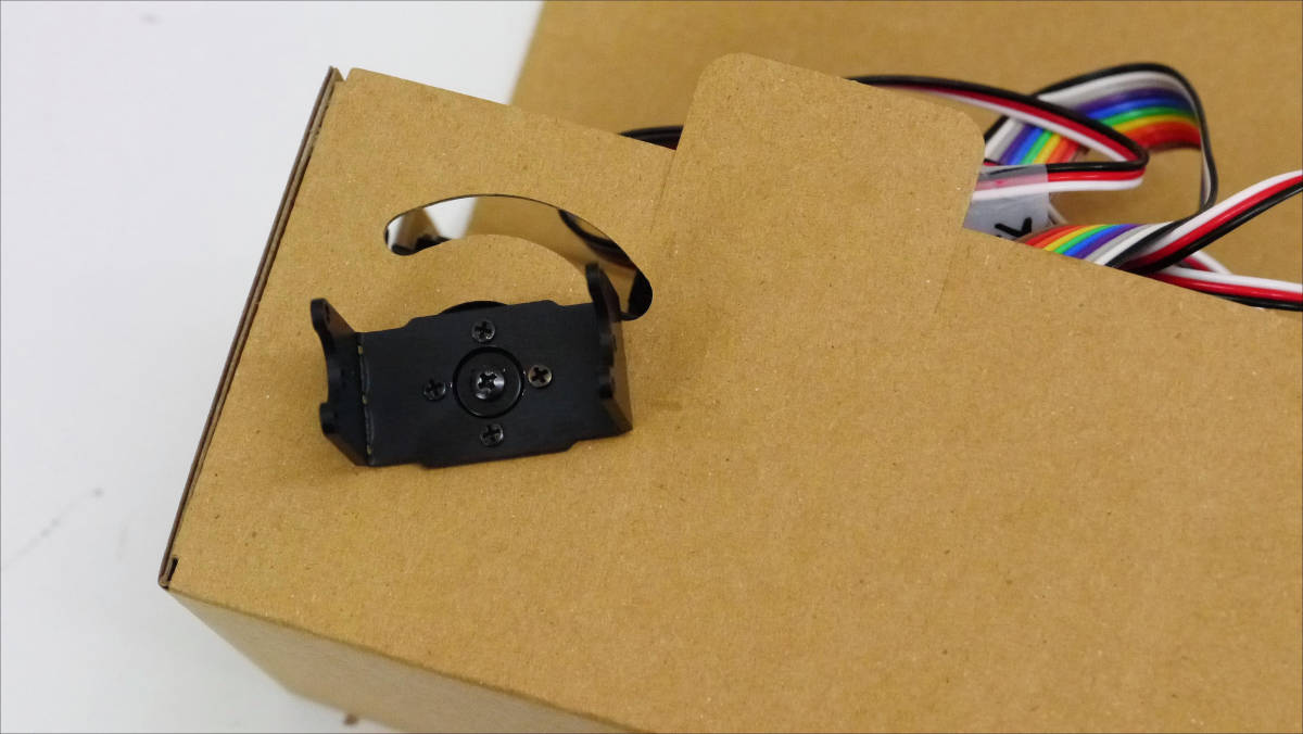
To the bracket of the arm part ... ....
I wore my arm.
Banzai.
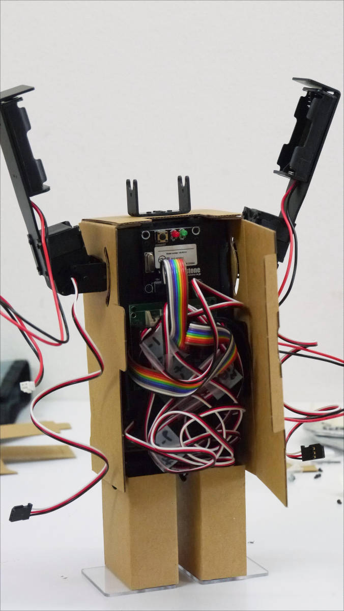
Pass the cable through the gap of the trunk ... ...
I will walk around like this.
Although there is no description concerning the wiring of servo cables (CN 1 - 6, CN 2 - 6) of both arms in the manual, wire CN 1 - 6 to the left of the red frame of the figure, and CN 2 - 6 to the right of the frame to the right.
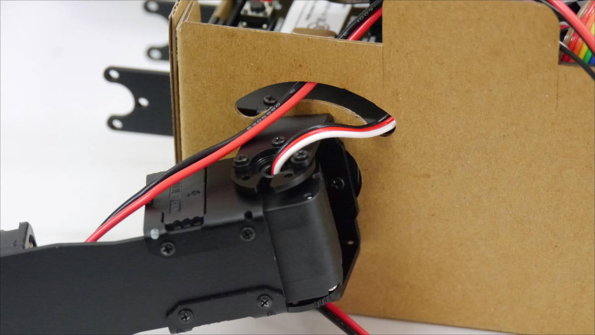
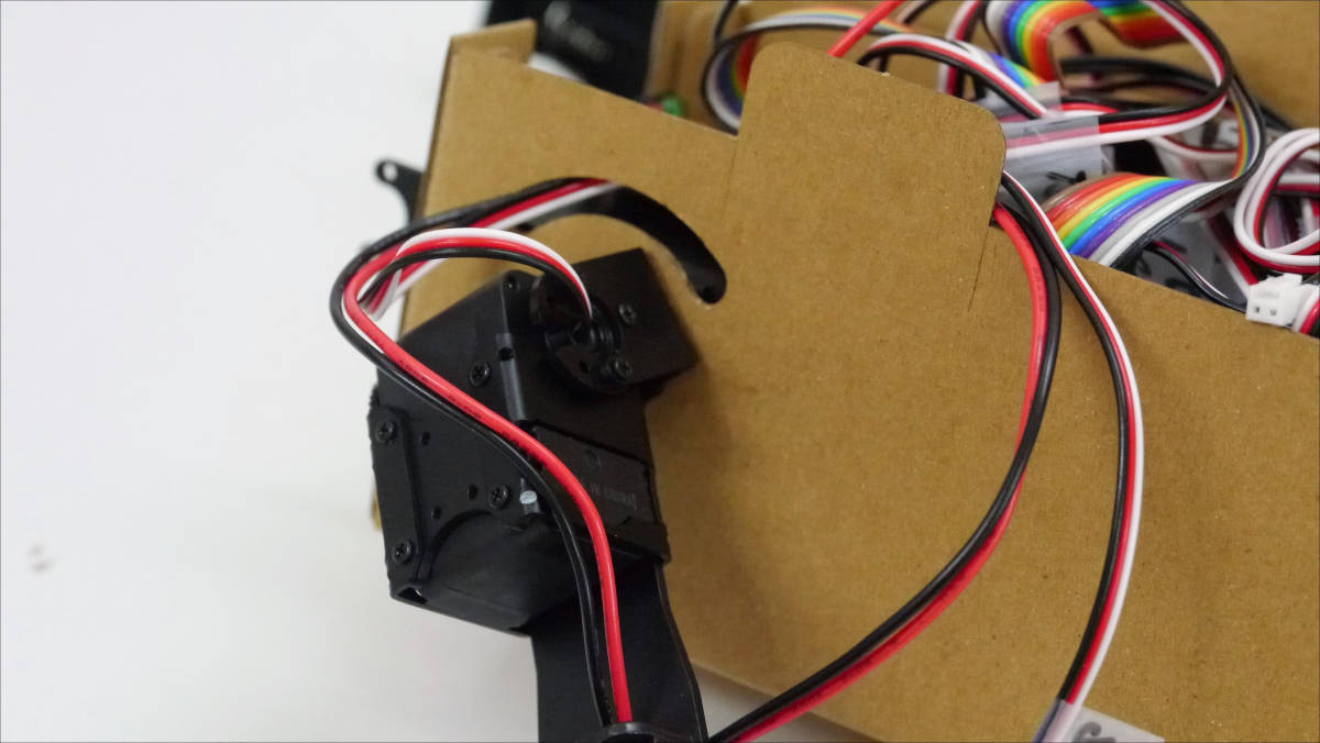
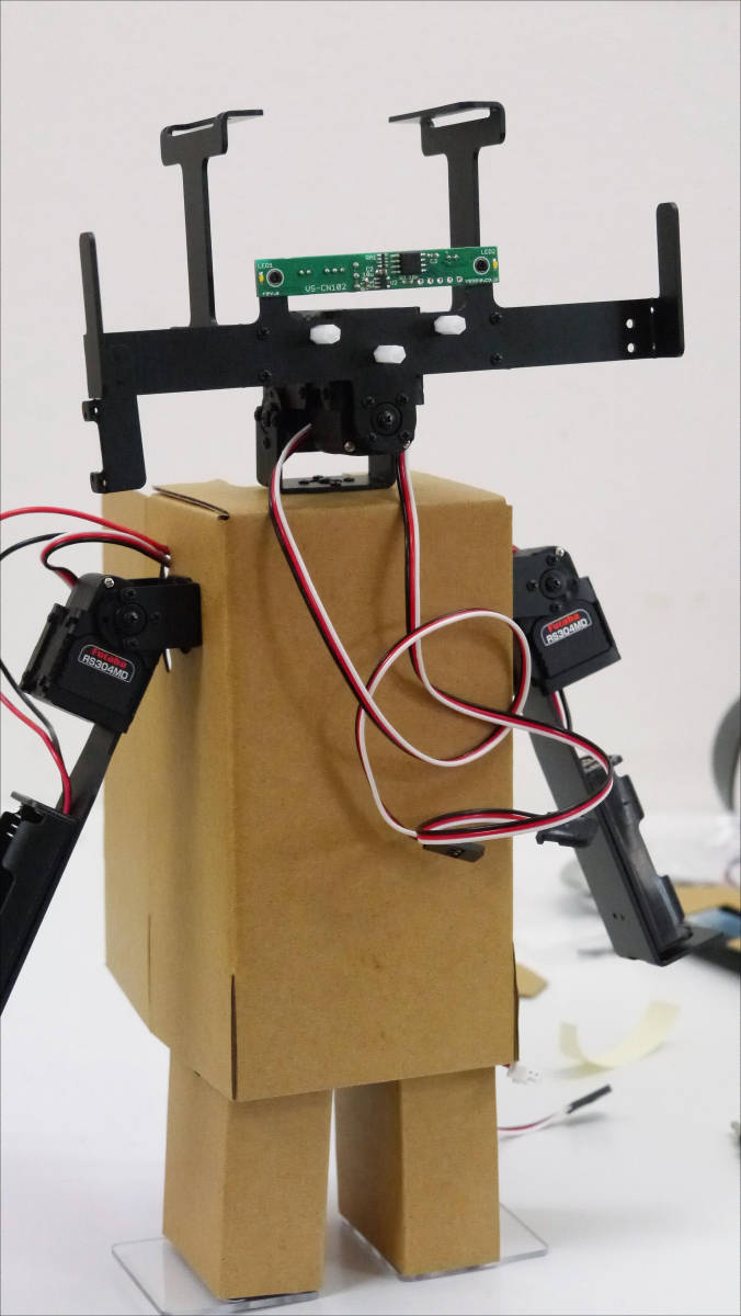
Next, I will prepare the neck part that I made earlier.
After setting the freehorn in the back of the servo with the stay attached ......
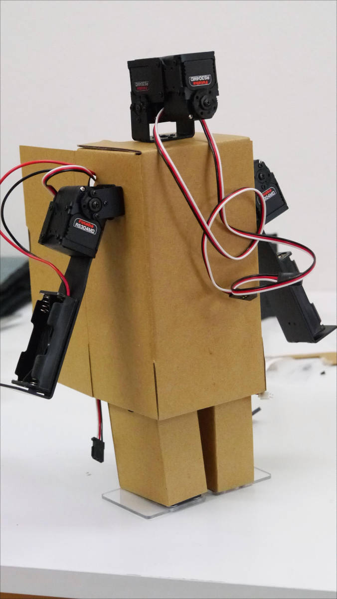
A neck is attached to the upper part of the torso.
Looking at it from the front. Far from being cute at this point it is slightly eerie.
The head part is worn on the neck.
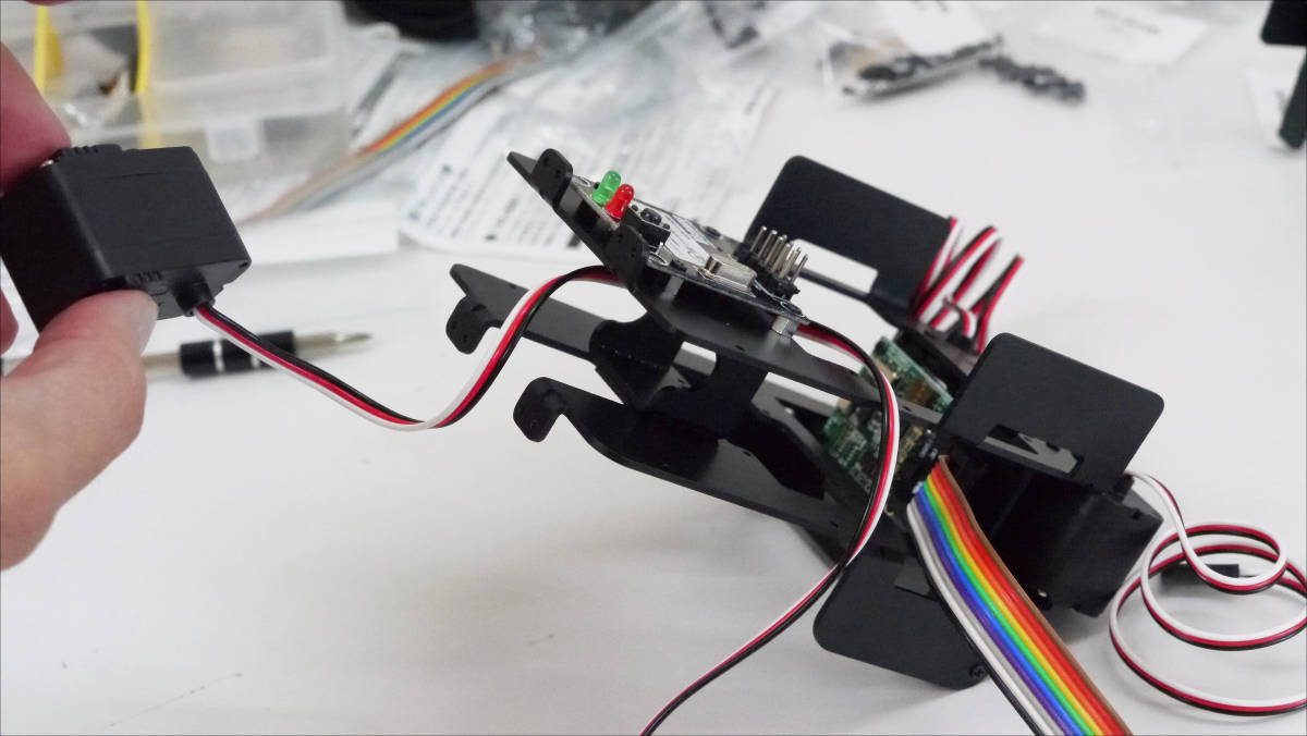
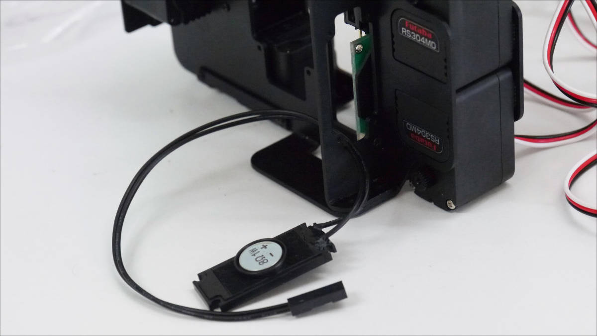
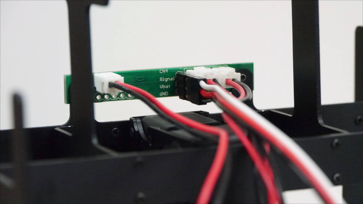
Plug the battery box cable, switch cable, power supply and LED cable into each connector.
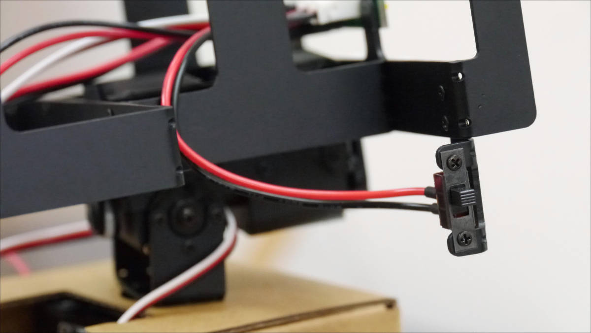
This is a side switch attached power switch.
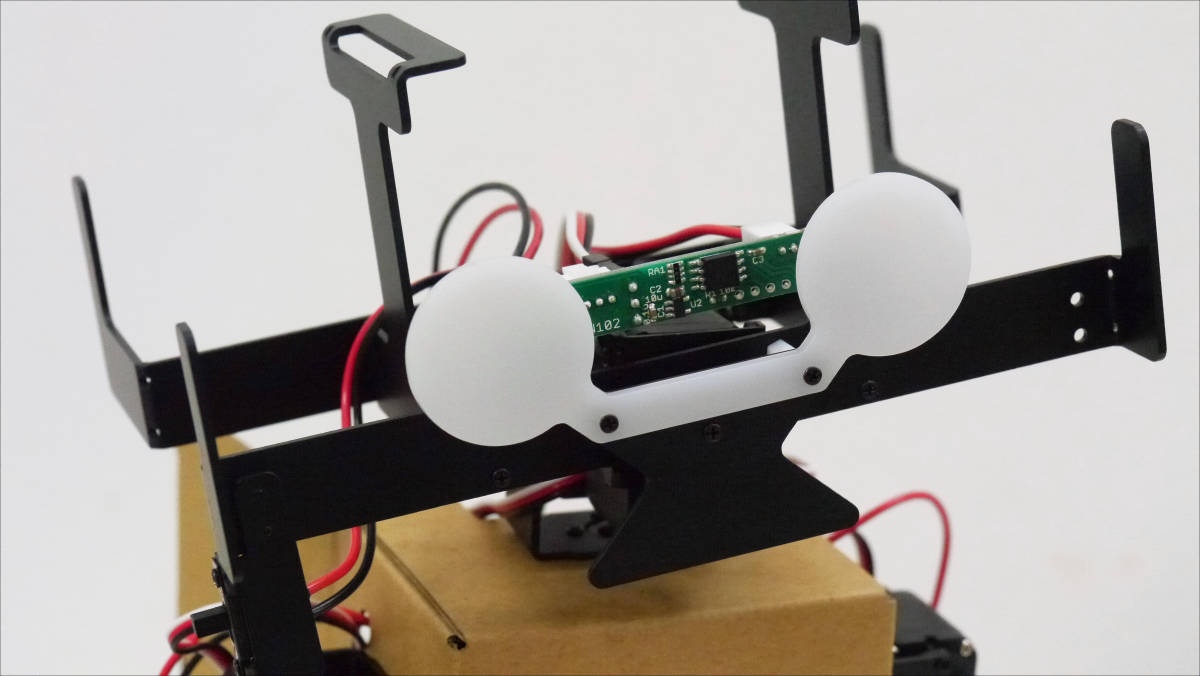
Wear eye screen and mouth part.
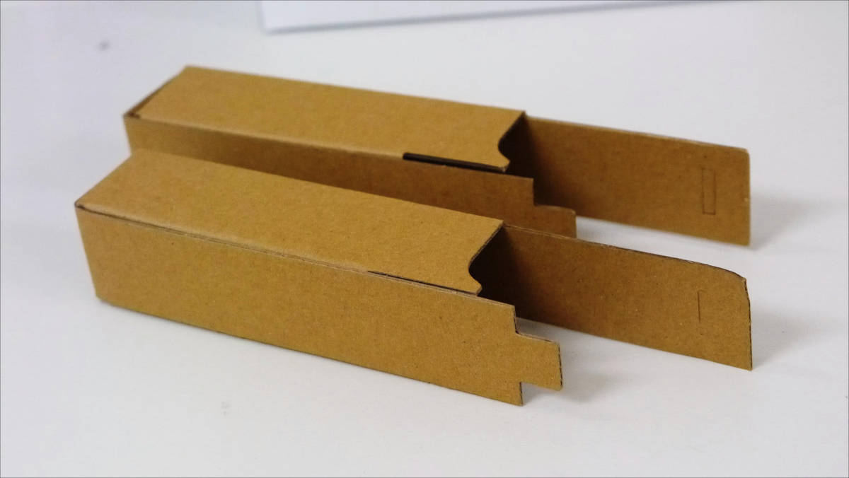
hereArm exteriorI will make it.
Assemble it into a box.
Of course, I made two pieces.
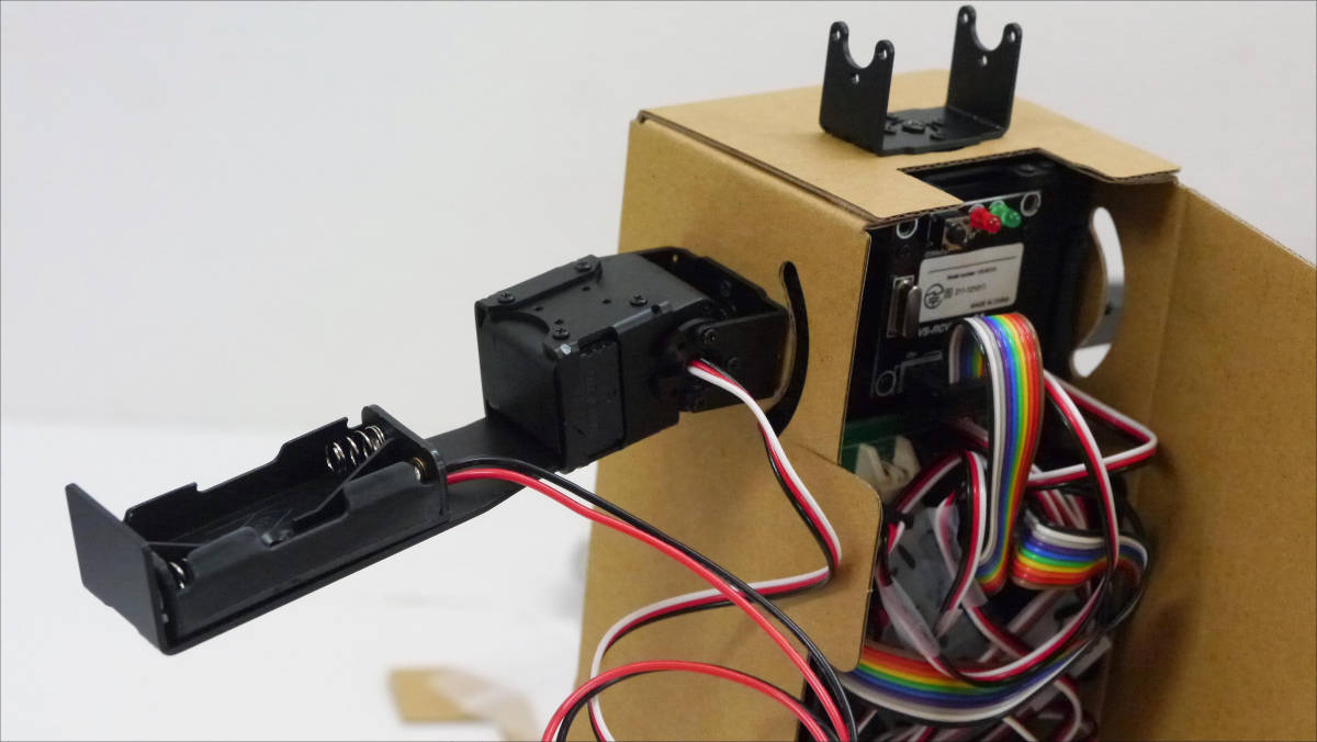
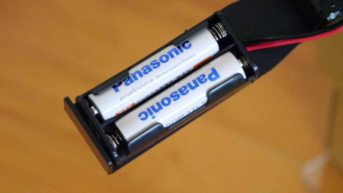
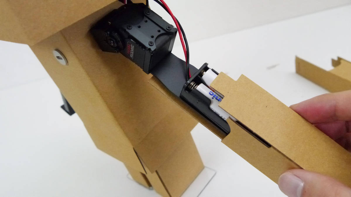
AAA Ni-MH battery is installed in the battery holder.Robodanbo is designated NiMH batterySo be careful.
Attach the exterior to the arm.
Tip portion folded ...
Fixed by inserting into a hole.
I got my arm.
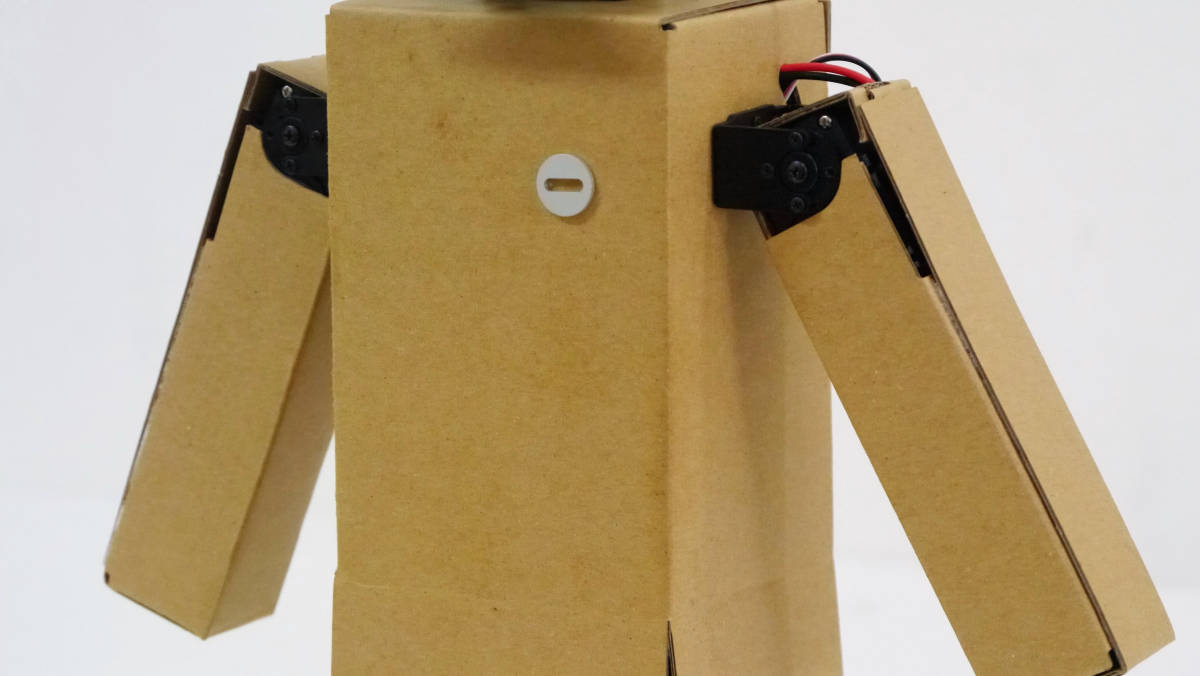
If you put a shoulder frame furthermore both arms are completed.
Although it is cardboard that is nothing to be changed ... ...
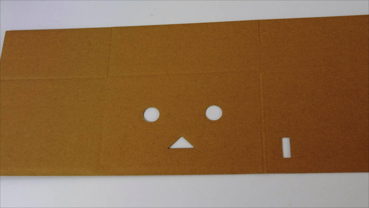
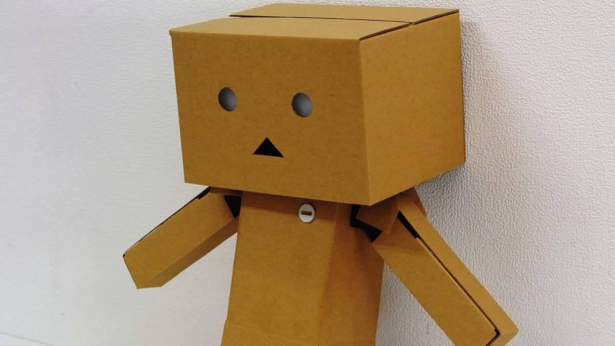
When you hollow out, a familiar face appears.
Assembled into boxes ......
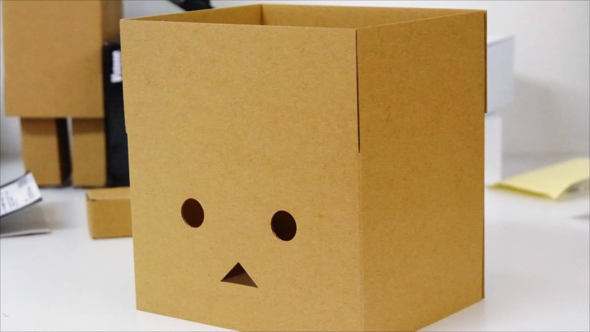
Danbo!

Wear it on the head ... ...

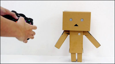
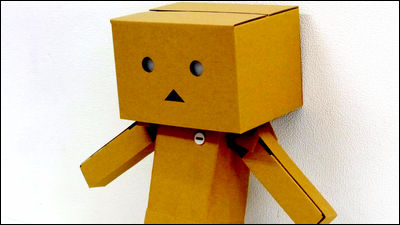
Completion
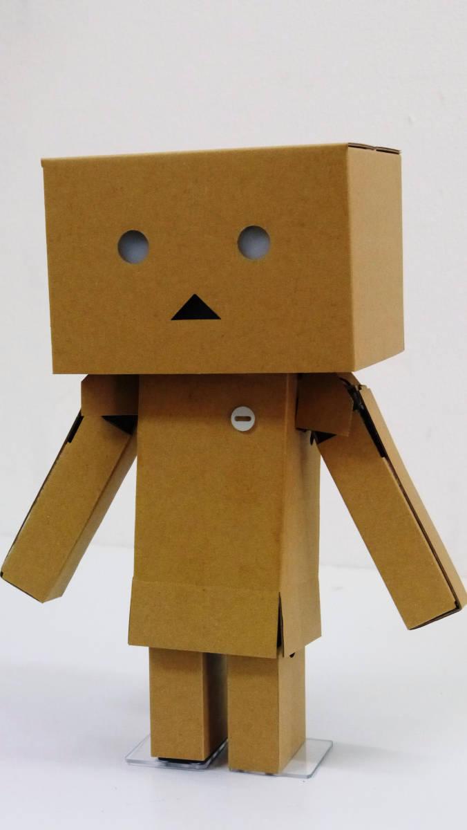
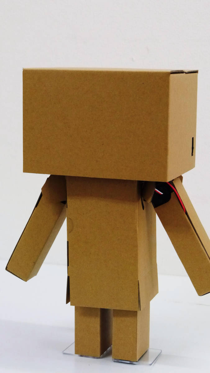
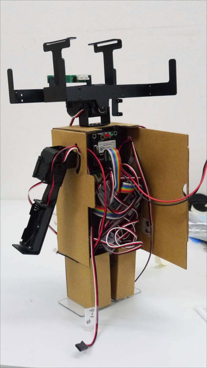
Robodanbo to lean against the wall. The day to dance is near! Is it?
Robodanbo is a wireless controller set with a base price of 79,800 yen, wireless controller "VS-C3" (unit price of 4410 yen) is 84,210 yen, Bluetooth communication module "VS-BT001" (unit price 8400 yen) The special set with the Bluetooth set with the gyro / acceleration sensor board "VS-TX001" (unit price of 18,870 yen) and the wireless controller "VS-C3" with 80,2800 yen is 80,960 yen I will.
· Continued
I trained "Robodanbo" and made various movements - GIGAZINE

Related Posts: