I tried making an adult science magazine "Patapata Radio-controlled watch" in which a patapata clock and a radio wave clock were united
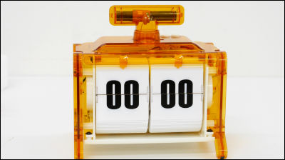
Newly added to adult science magazine released from GakkenPatapata radio clock"Has been added. Since it means that you can create old-fashioned patapata watches yourself, I actually made it.
Patapata radio clock | adult science magazine | adult science .net
http://otonanokagaku.net/magazine/vol38/index.html

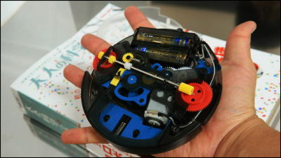
What kind of patapata radio clock is completed with this kit and what kind of movement is done can be understood by watching the following movie.
A patapata radio clock has been completed so try inserting batteries - YouTube
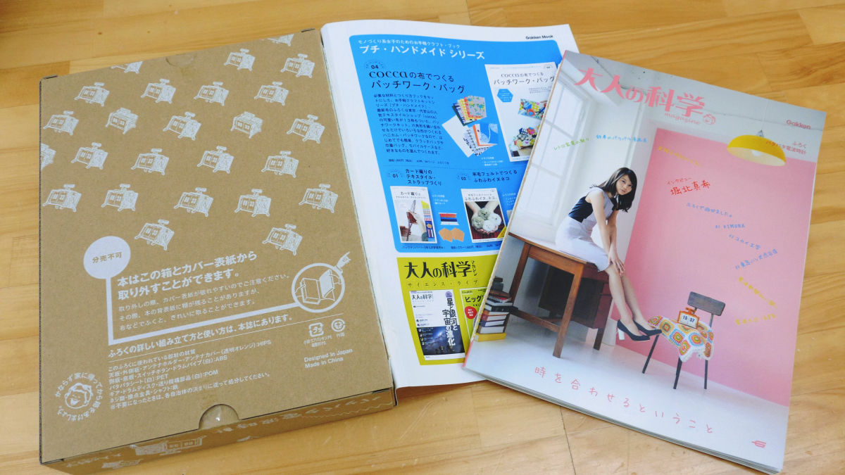
This adult science magazine's watch has a pattapat radio clock attached.
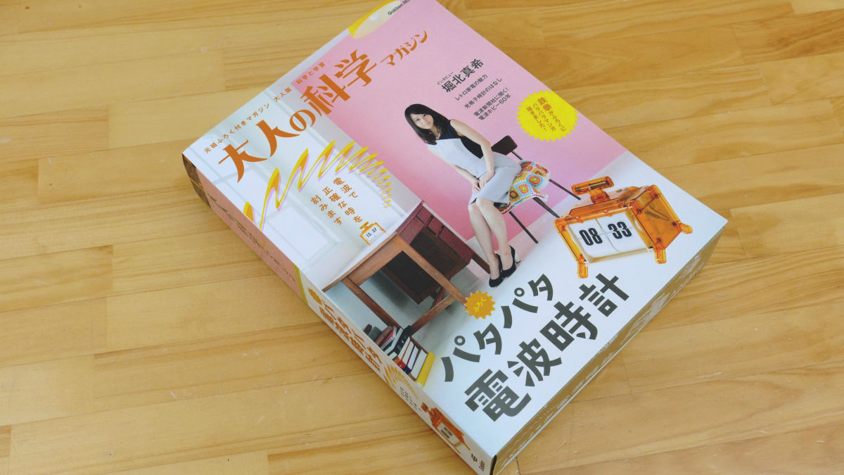
It is said that the book and the fukuro are together, or the thickness over which the wiper exceeds the body overwhelmingly.
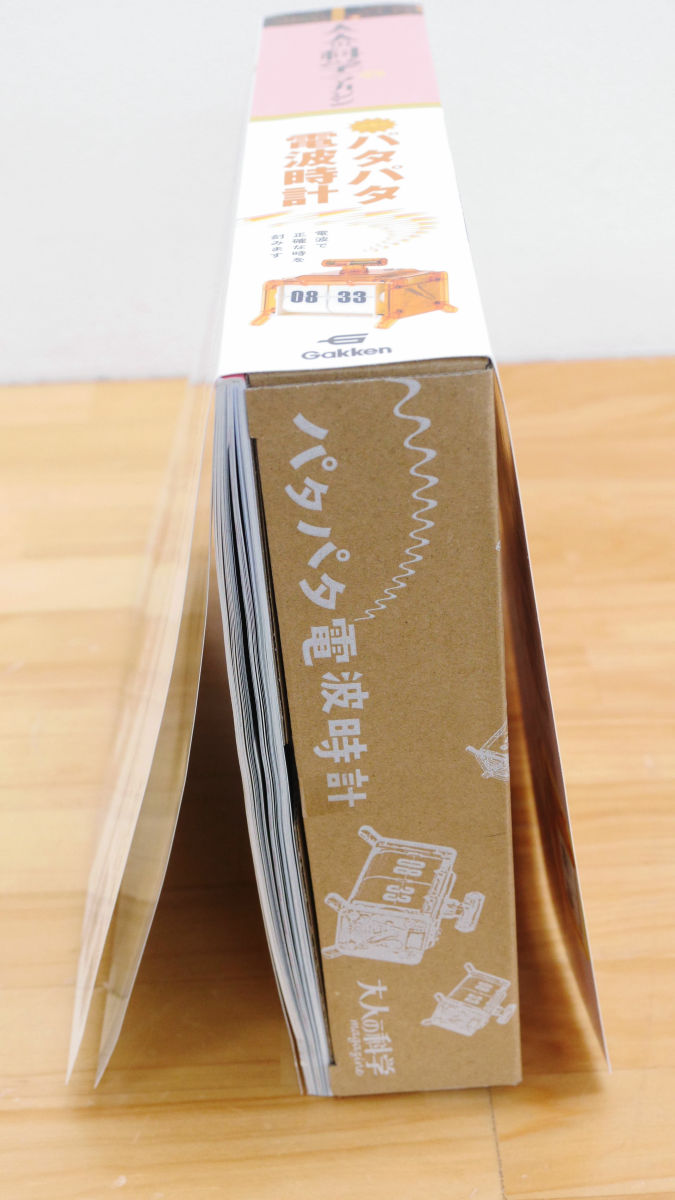
I thought about removing the box ......
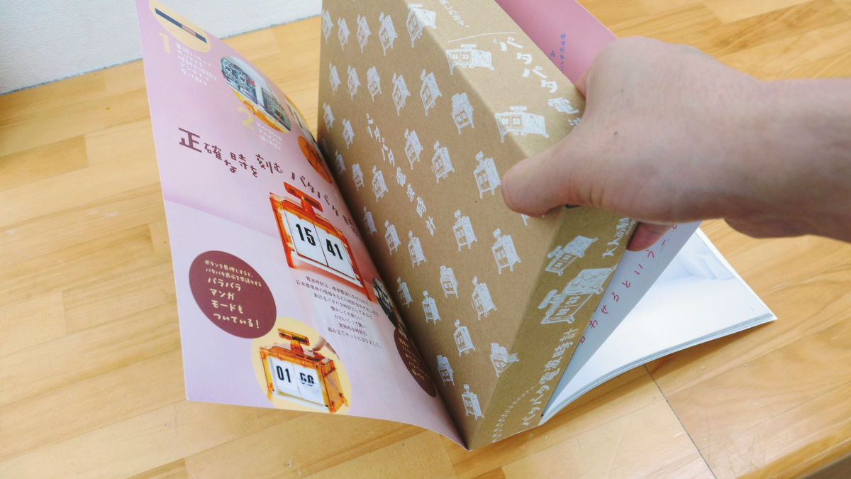
The magazine seems to be out.
Inside the box is a radio wave clock before assembly.
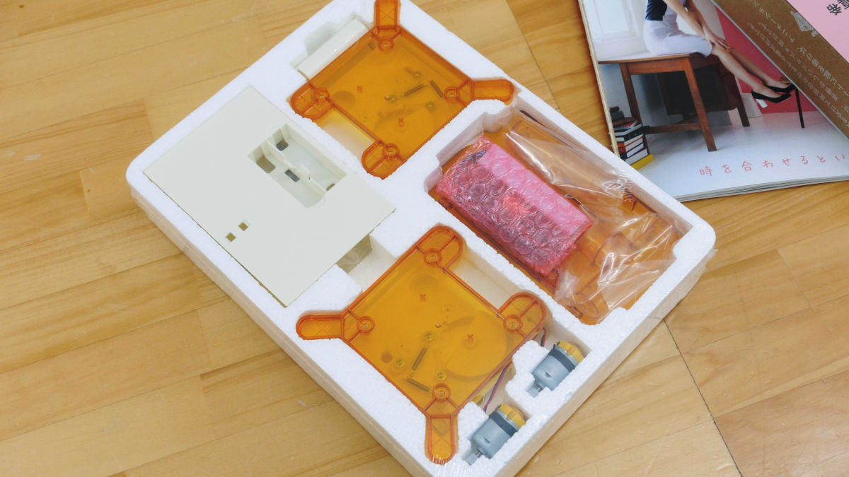
The back side is filled with scattering parts.
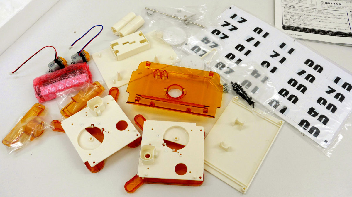
When opening the parts and arranging the parts, it looks like this.
The first thing we assemble is this white backboard part and printed circuit board.
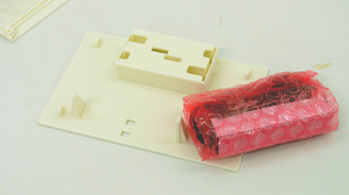
The printed circuit board and the antenna are wrapped in red nylon bubble wrap. Copper antenna wire is weak, so be careful not to cut it during work.
Attach the board to the insertion part of the back board.
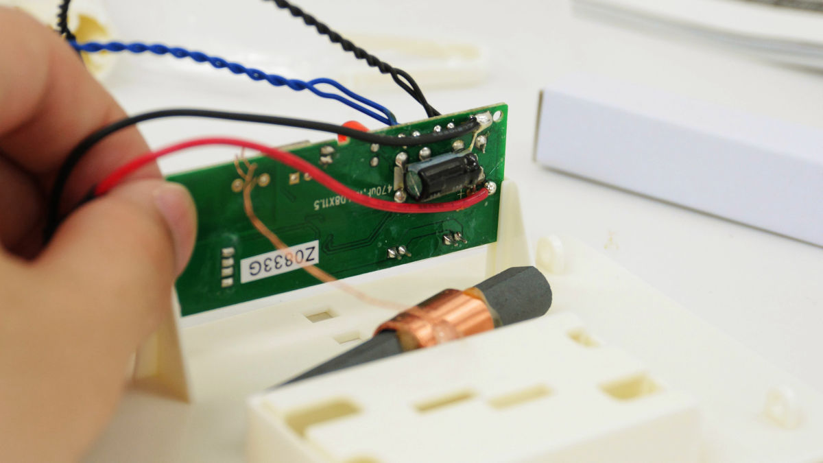
Place the board in the back plate so that the cords are on the top with the one with the red lamp facing outward.
Next with this fastener ......
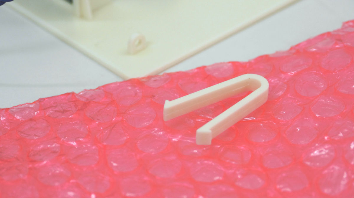
Fasten the board and backboard. At this time, it is a point to sandwich the blue code between the substrate and the fastener intentionally.

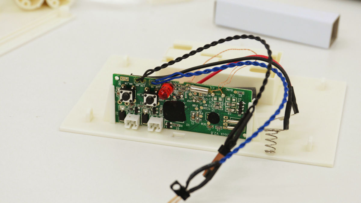
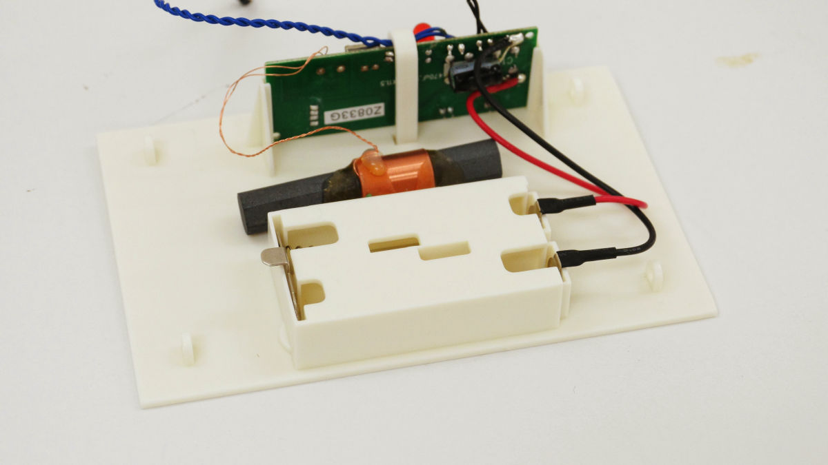
Insert the battery contact bracket into the battery box.
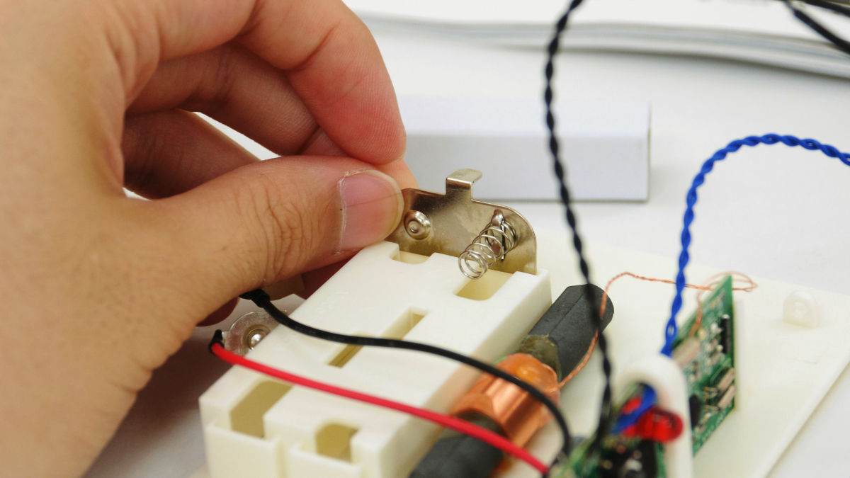
Similarly insert the black cord outside the back plate and the red cord into the end of the battery box inside the back plate. There are two black cords, but please insert the shorter cord into the battery box, the cord is not twisted.
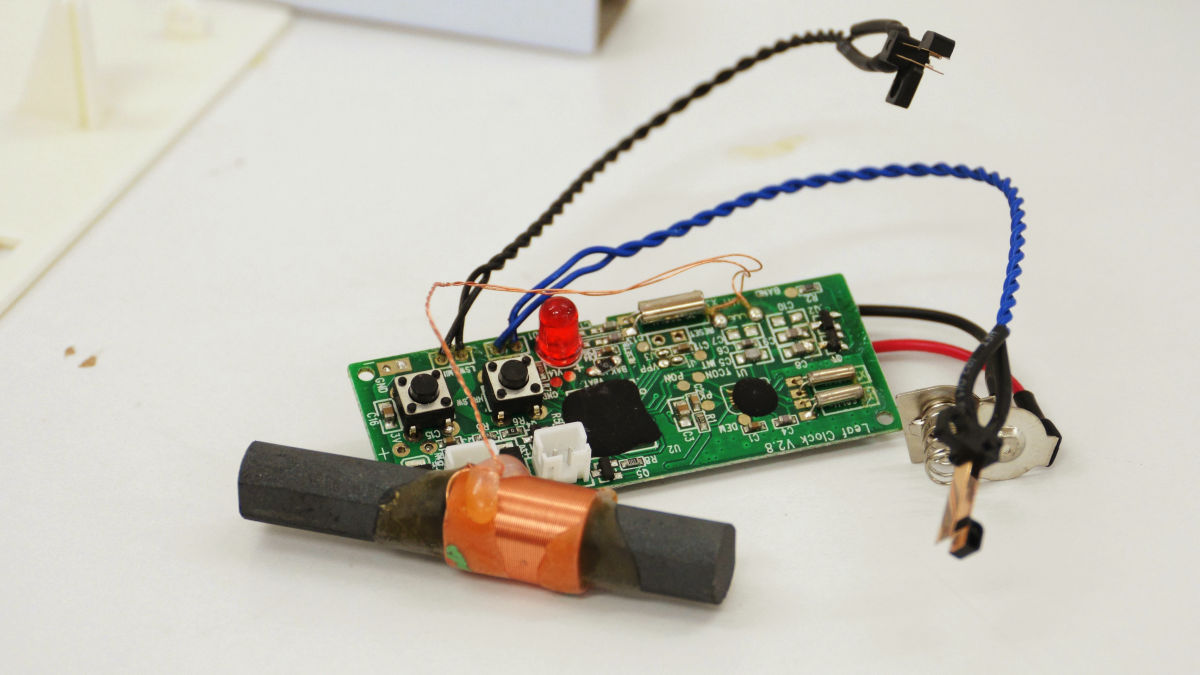
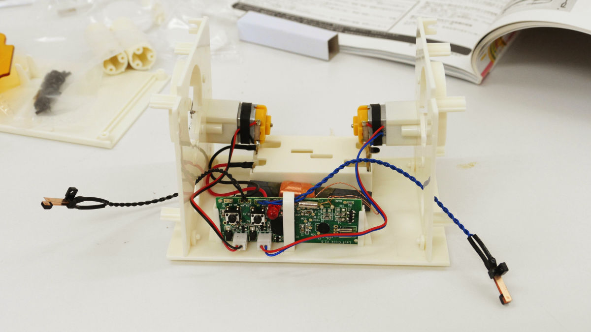
Next is the installation of the motor.
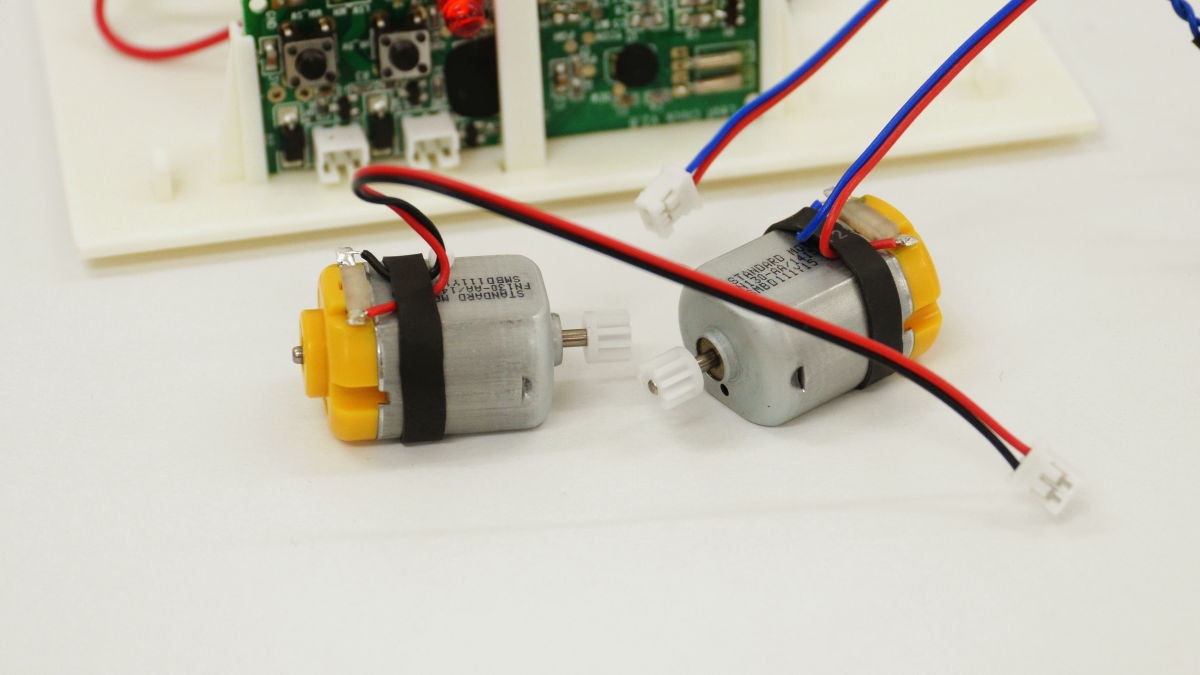
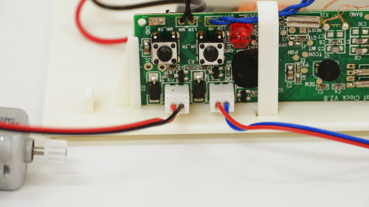
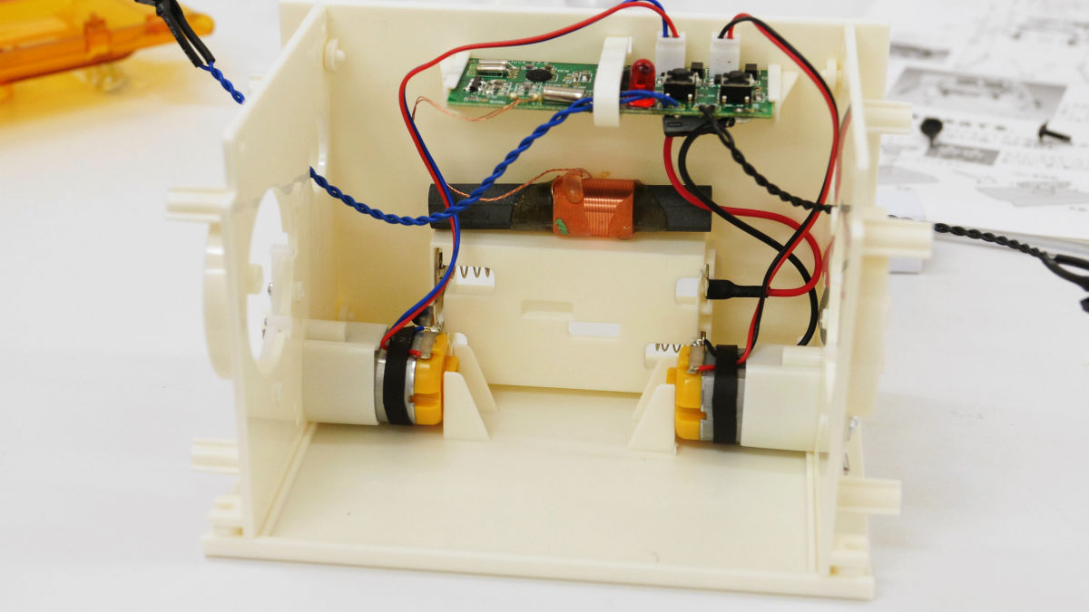
There is a connector at the tip of the cord attached to the motor, and the one with the silver colored bracket can be seen is on the top.

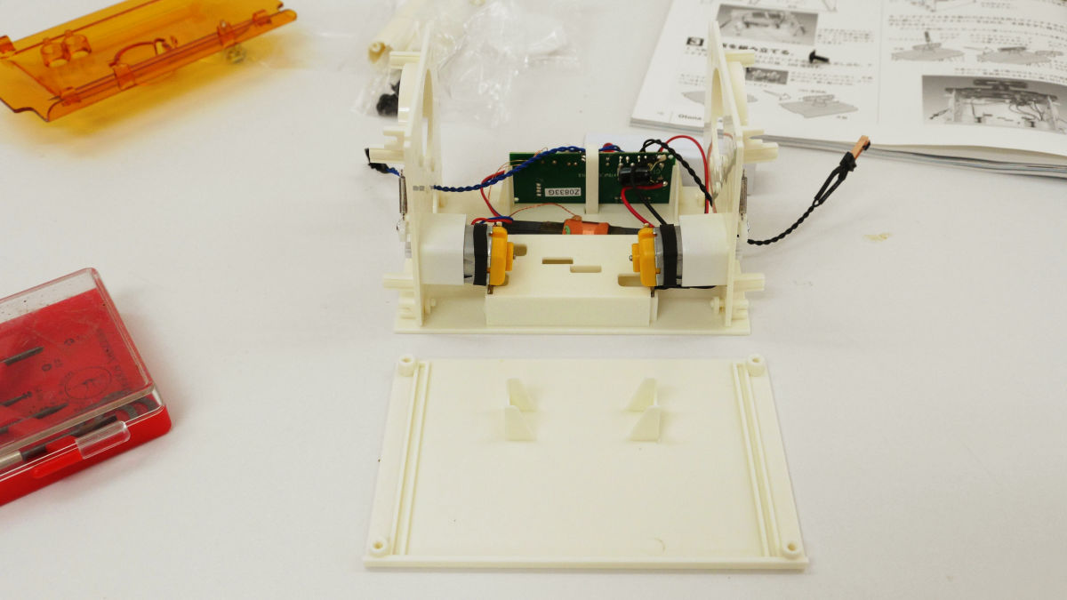
Plug the motor of the red / black code motor on the left side of the printed circuit board and the motor connector of the red bluecode to the right side.
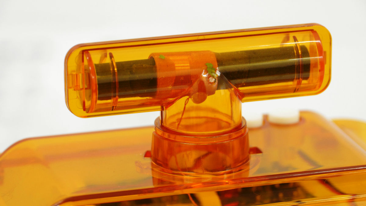
This part becomes the side part of the pattapata radio clock.
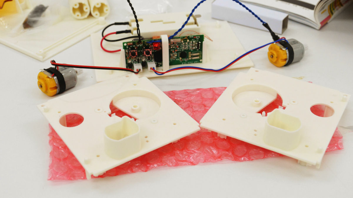
"R" and "L" are written in the near view, "R" is the right side plate, and "L" is the left side plate.

There are "pins" and "guides" that connect the side plate and the back plate, so fit them in there. By the way, it is the left side board which is settled at this time.
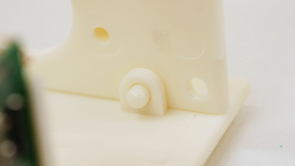
When fitted, a pin will enter the guide part like this.
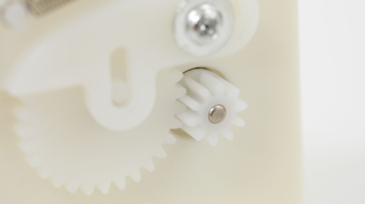
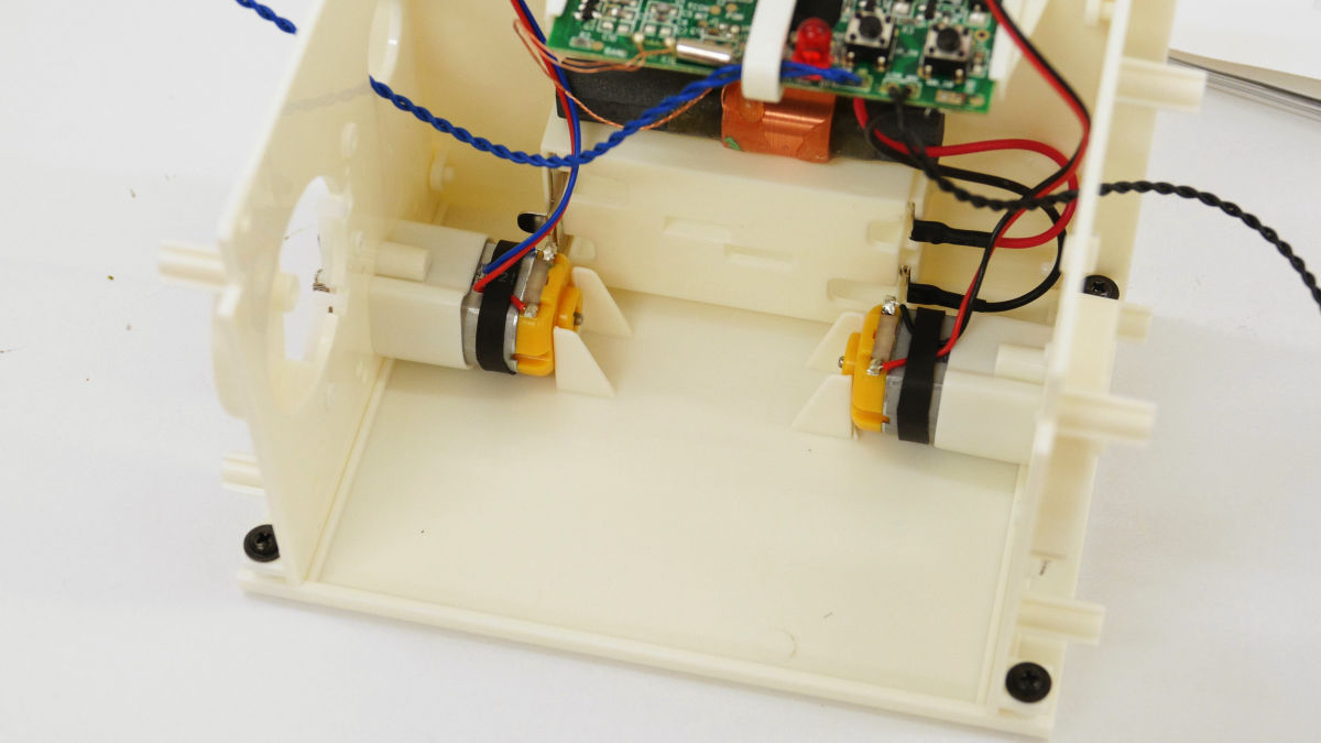
The motor is fixed to the motor holder so that the cord faces the board side.

Looking from the back, the gear part of the motor is engaged with the gear of the side plate successfully. If the motor does not fit properly, you can turn it by turning the gear on the side plate a little.
Pull the blue leaf switch cord outward through the hole in the side plate.
When I pull up the right side board in the same way, it looks like this.
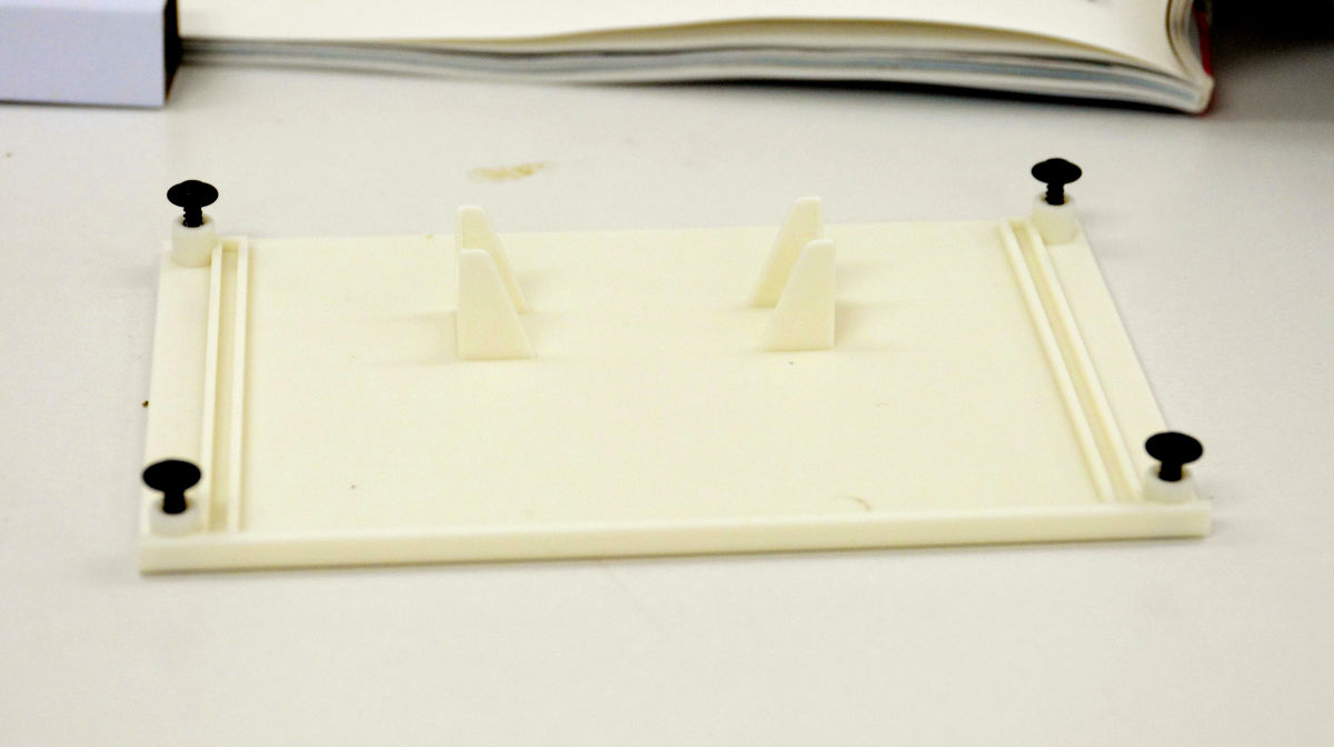
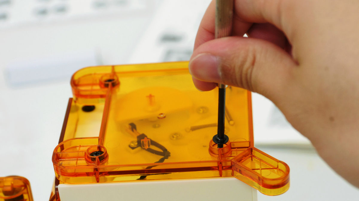
Next is the bottom plate and screw with screw.

In the four screw holes of the bottom plate, stop the flanged head with about 5 mm as it does not stop the flanged screw completely.
After removing the screw ... ....
Place the parts that we had assembled up to the bottom plate from the part with the motor. Then, the motor is fixed at the protruding part of the bottom plate.
Stop the bottom plate and side plate with the screw with the brim.
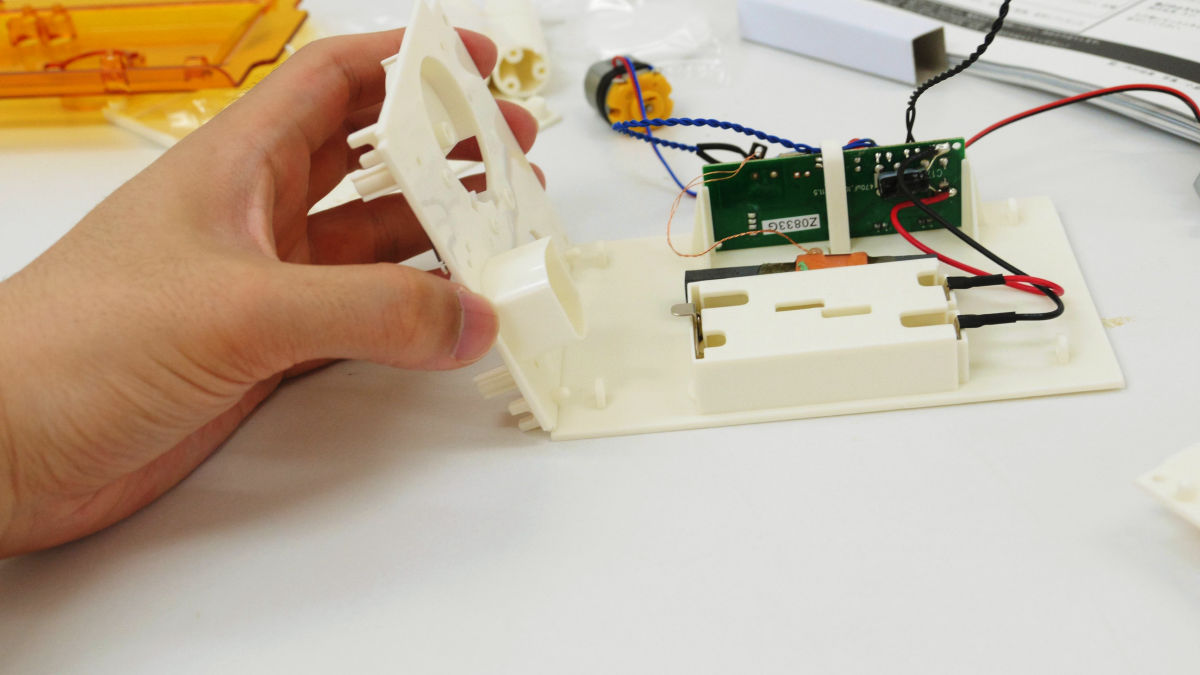
This is the top plate part.
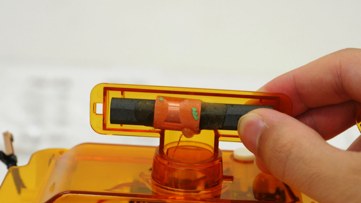
Put the antenna holder in the hole in the center of the tabletop ... ...
Turn 180 degrees counterclockwise.

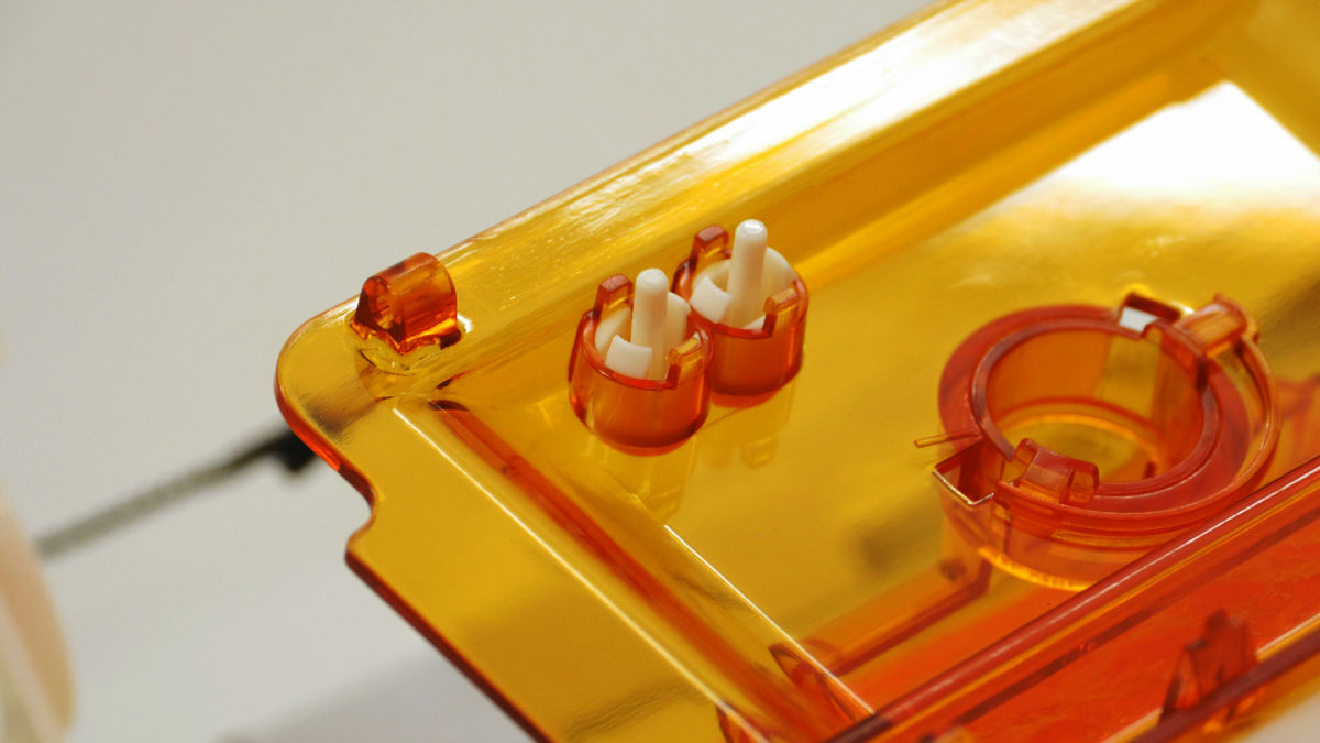
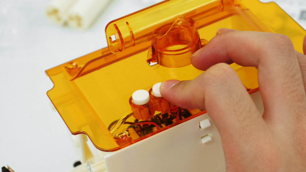
There are two holes at the edge of the top board, so we put in the white switch parts.

Switch looks like this from the back. Let's make sure that the tabs are stuck firmly.
Place the top board on the body.
Please check if you hear "click" when you press the switch.
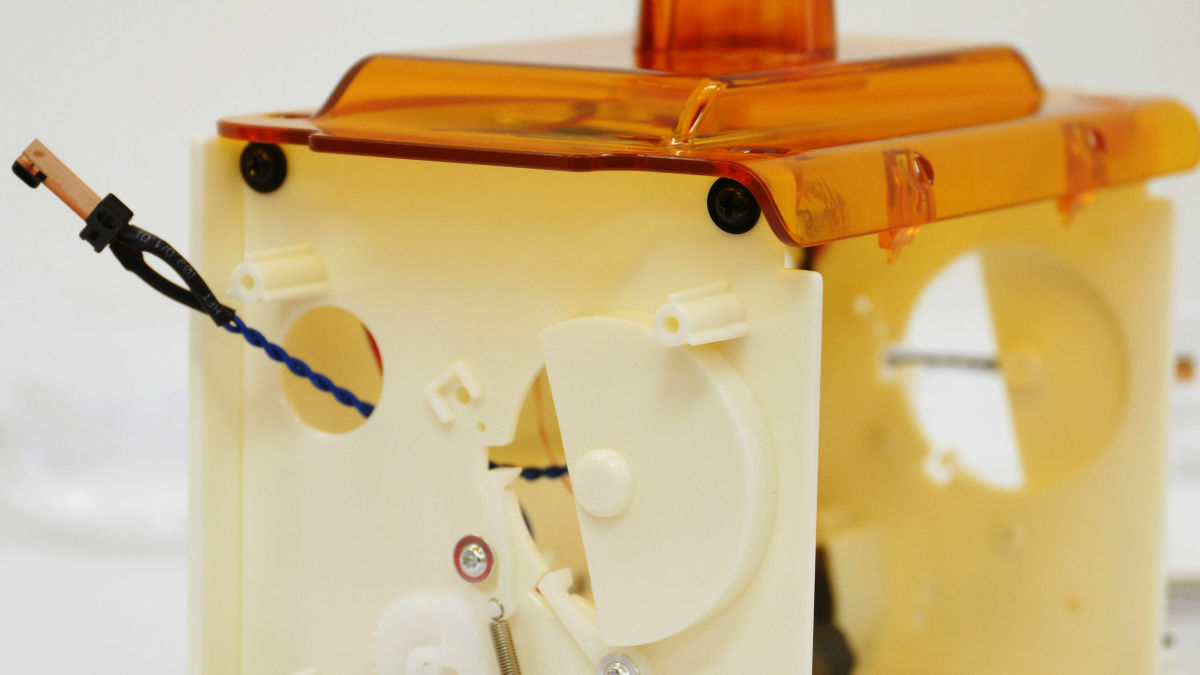
If the switch rings firmly, secure the top board and side plate with a screw with a collar. However, as seen from the large open side of the assembled main body, only the screw hole in front of the right hand is not fixed yet.
Pass the antenna through the hole in the top board.
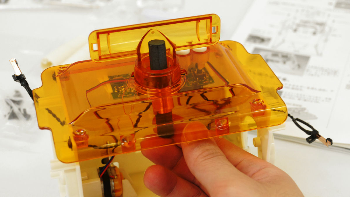
Fix it ... ....
Completing the placement of the antenna if you cover it. This eliminates the need to work while worrying about the copper wire of the antenna.
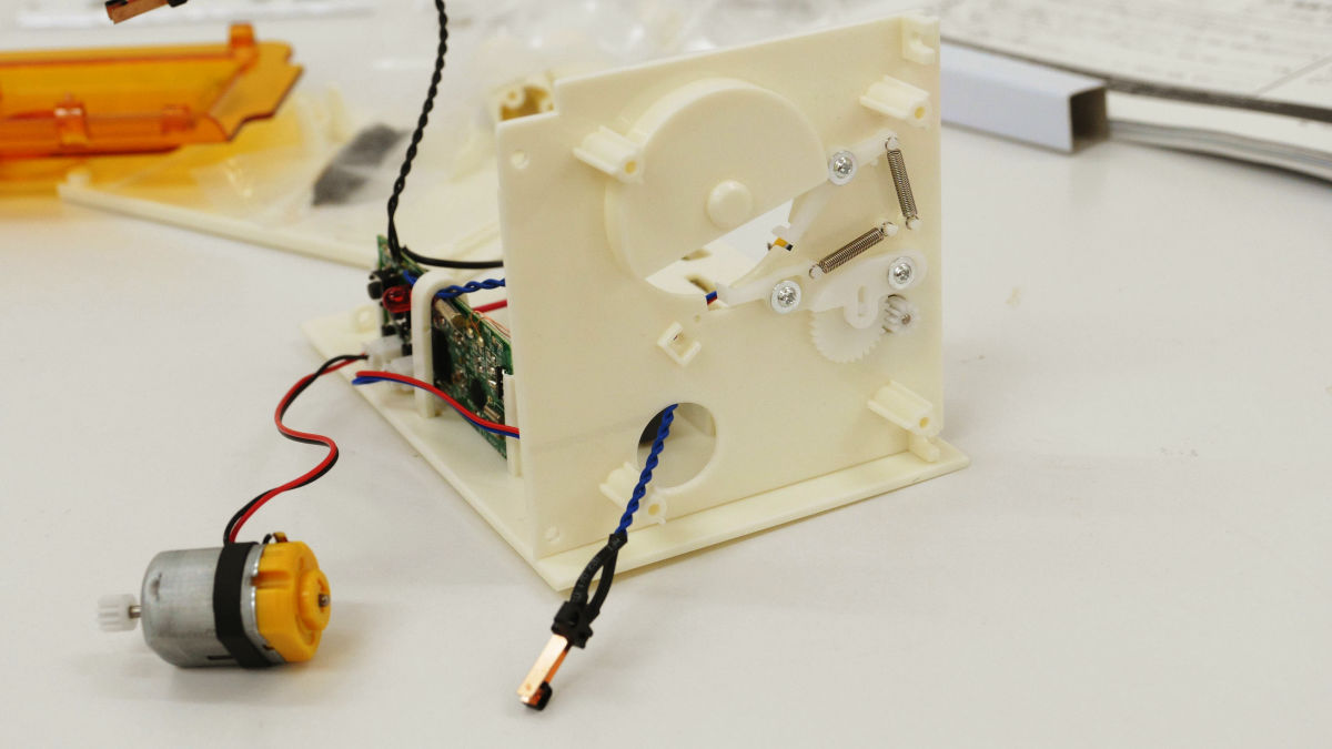
The current state is like this. The code of the leaf switch is coming out from the side plate.
Next I will assemble the drum which will become the axis of the scatterpart part.
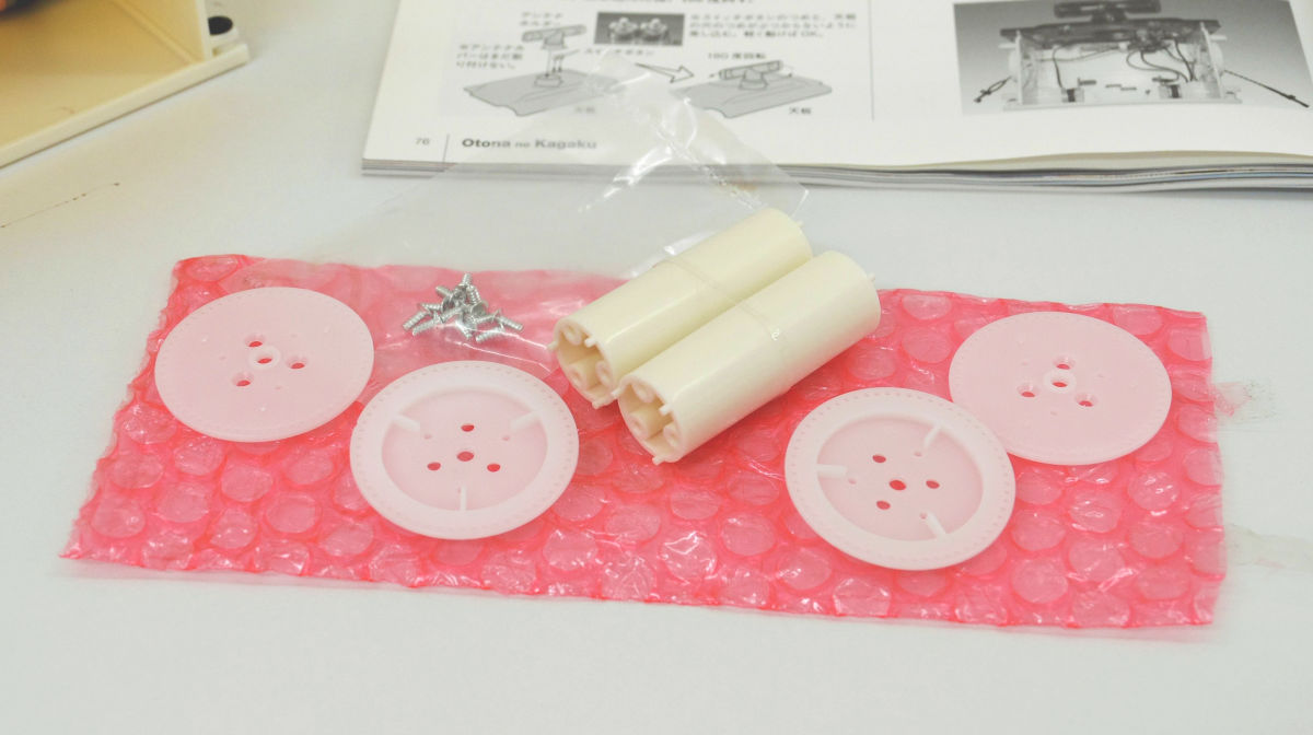
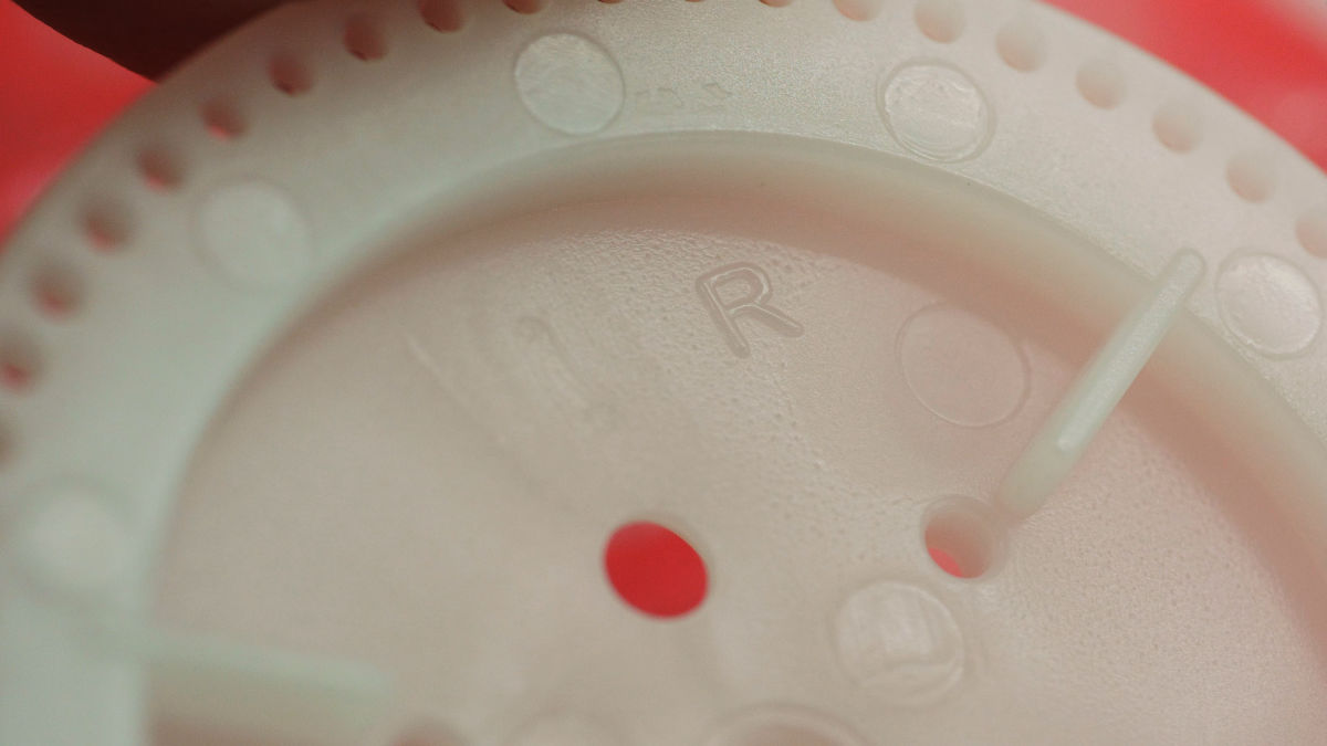
Also in the gear parts with big unevenness of the drum part, when viewed near, the notation of "R" "L".
When assembling this ... ....

It will be like this. Stop the screw so that the gear part of the gear part faces outward.
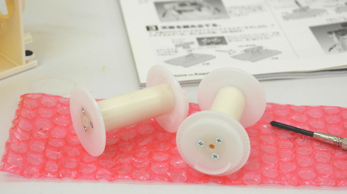
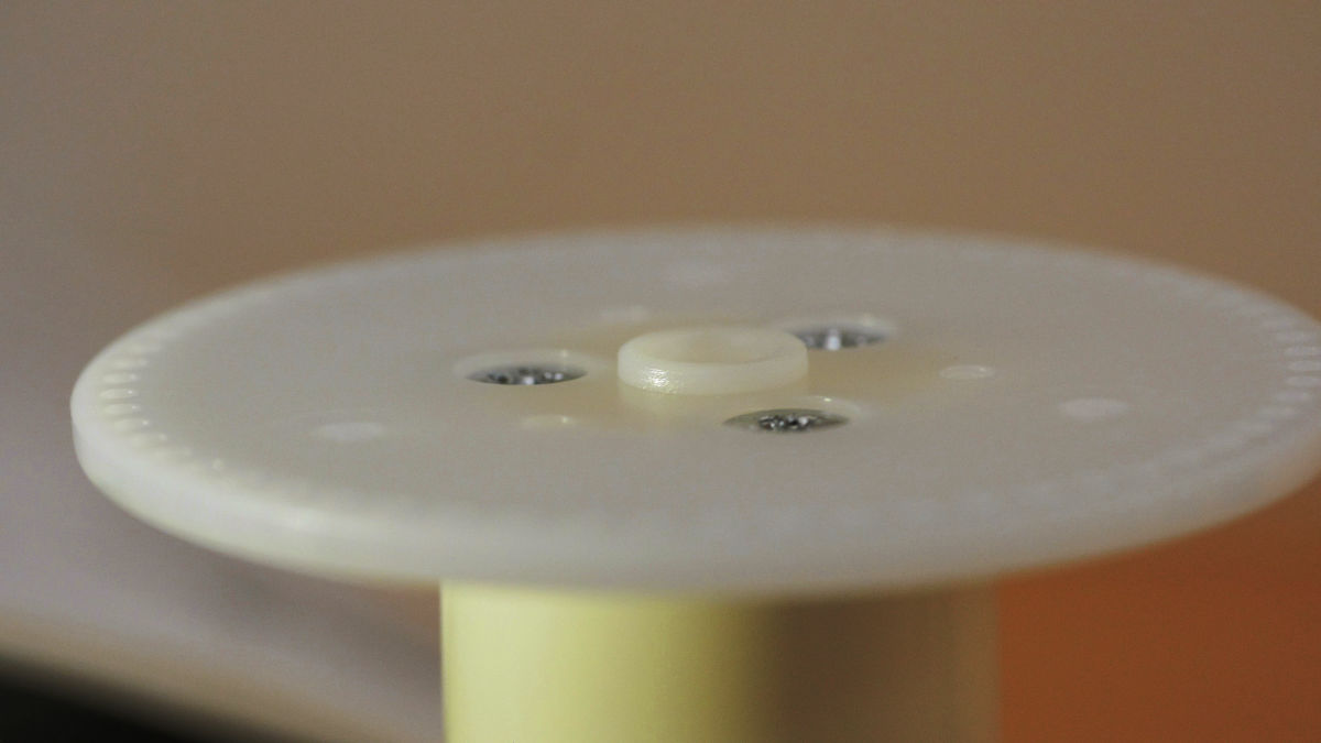
Tighten the screw securely so that the head of the screw does not come out, Let's fix the flat disk parts with screws so that the small protruding parts go out.
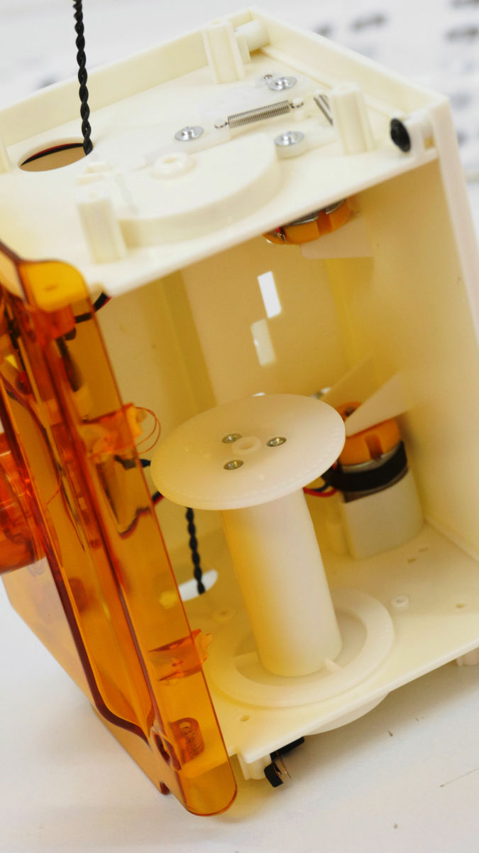
Push down the main body so that the left side is down ... ...

Place the left drum so that the gear part faces down.
Since the screw in front of the right hand is not stopped, install the drum so that the gear part of the right drum faces up while lifting the right side of the main body.
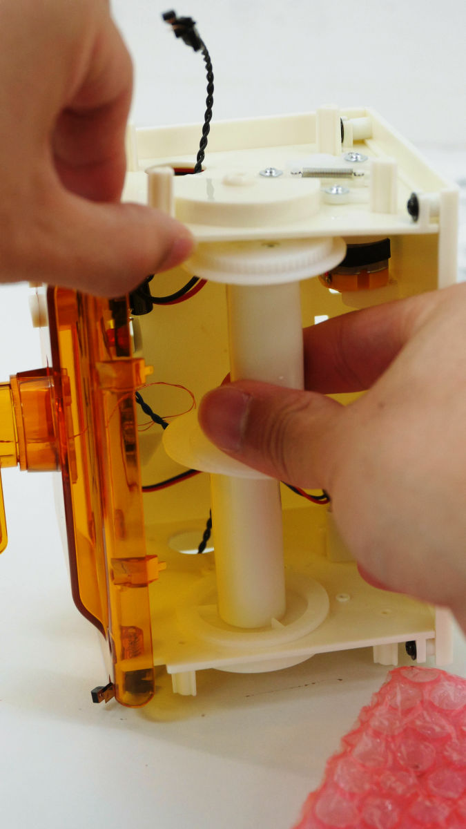
Pass the silver shaft through the right side.
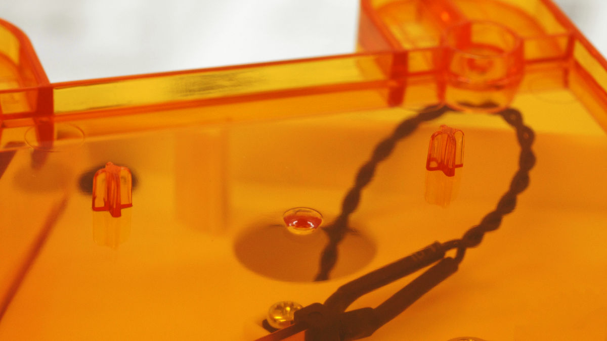
Put a stopper with a cellophane tape through the hole through the shaft, fix the part that did not screw the right front.

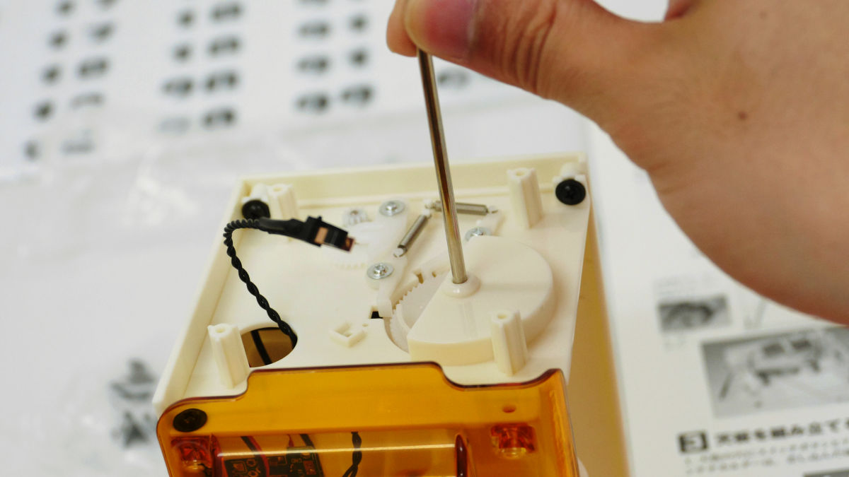
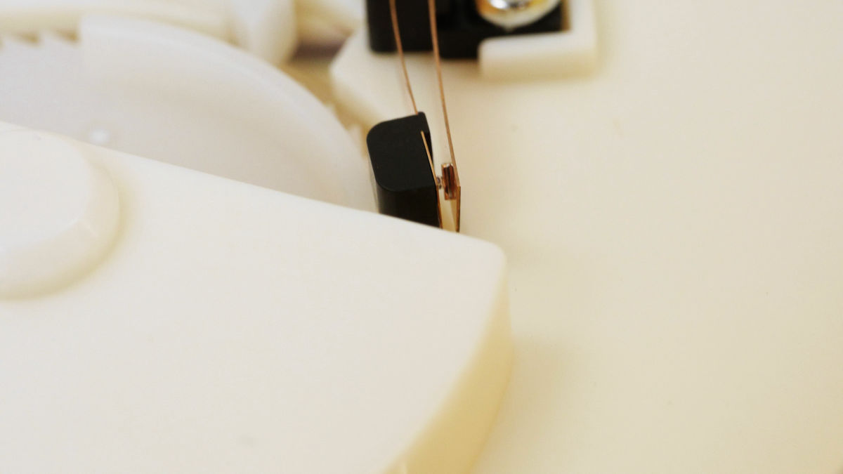
Fix the leaf switch to the side, use a silver pan-head screw with a round head to fix it.
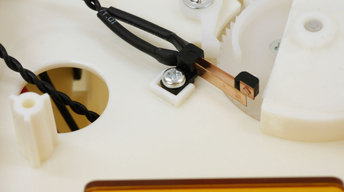
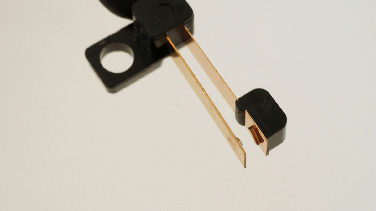
This is the tip of the leaf switch. Make sure that the metal plate at the tip is parallel and if it is not parallel, please bend it with your finger so that it becomes parallel.
We will check the operation of the leaf switch.
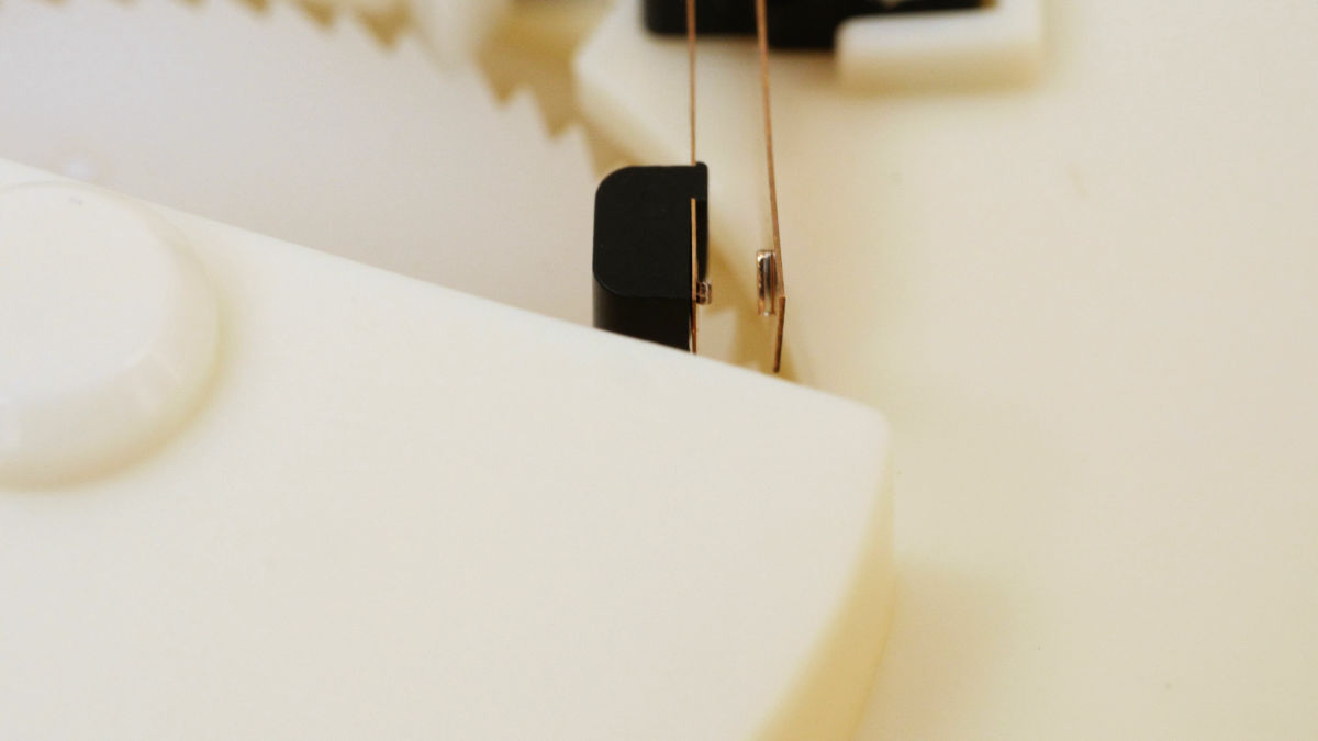
It is OK if the metal plate part comes into contact when turning the drum.
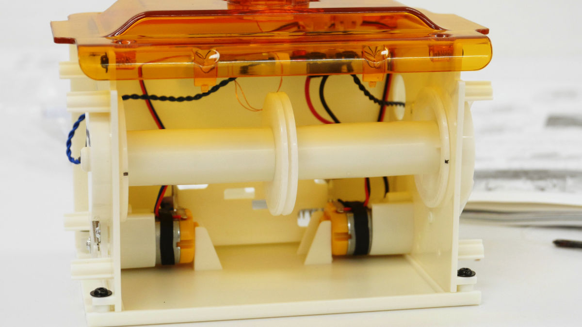
When you insert 2 AA batteries in this, the drum will rotate to the determined position and stop. The movie that reflects the situation of actually rotating and stopping is from the following.
Putting a battery in a pattapata radio clock and checking operation - YouTube
Once you insert the battery, the drum will rotate and the part of the gear end where there is a little dent will come to the center and stop. Since it is difficult to understand the dented part considerably, it is good to mark with a pen.
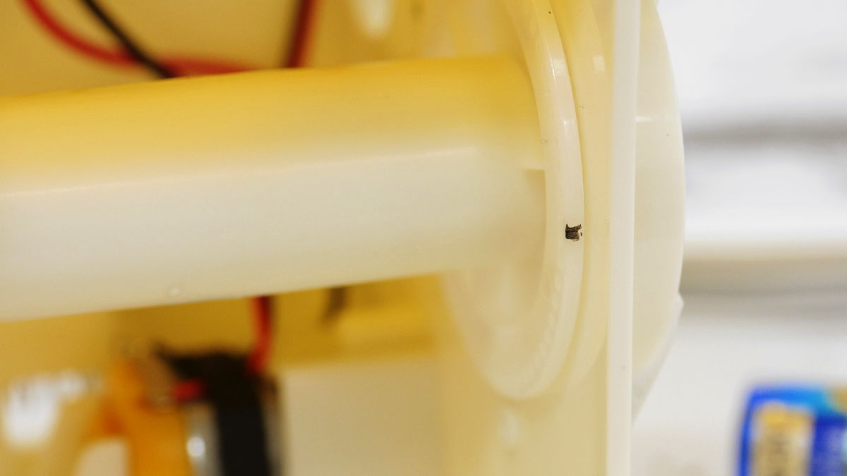
When you mark it, it looks like this. Remove the battery after marking it.
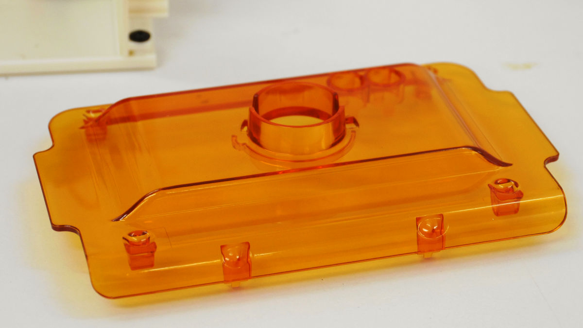
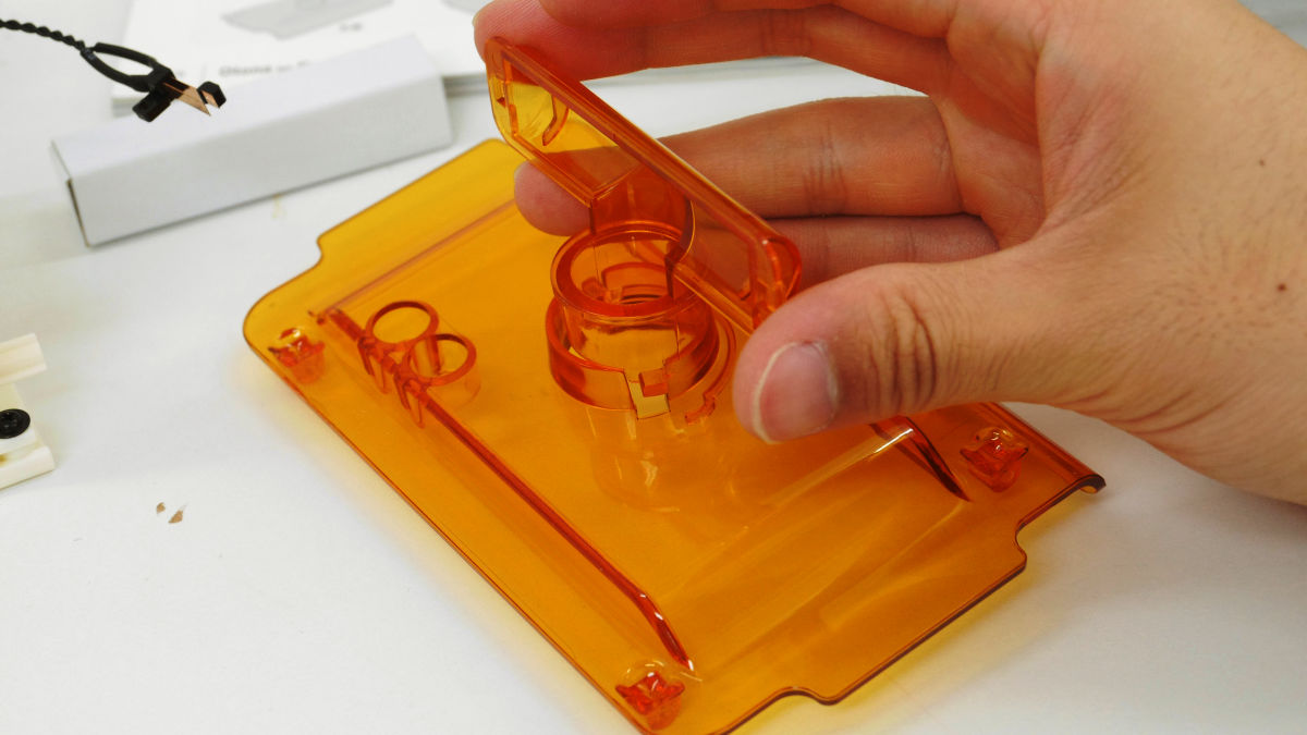
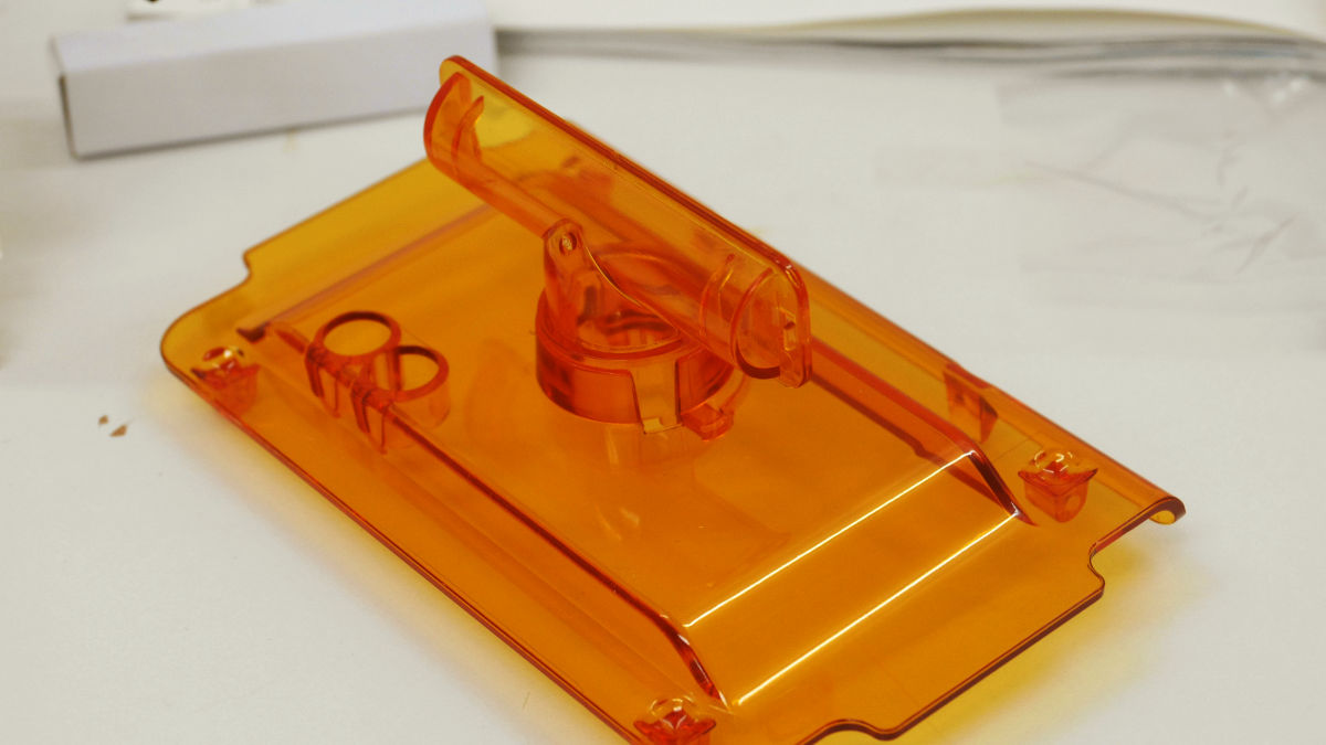
At the end is the work of attaching the outer frame part to the main body.
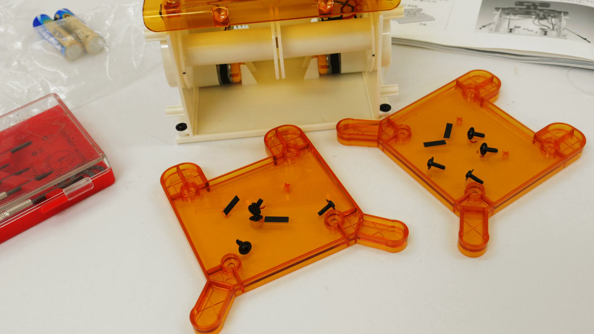
Attach the outer frame so that this protrusion faces the main body side.
Four spots with one flange with flanged screws, and eight places on both sides fixed.
Finally urethane cushion ......
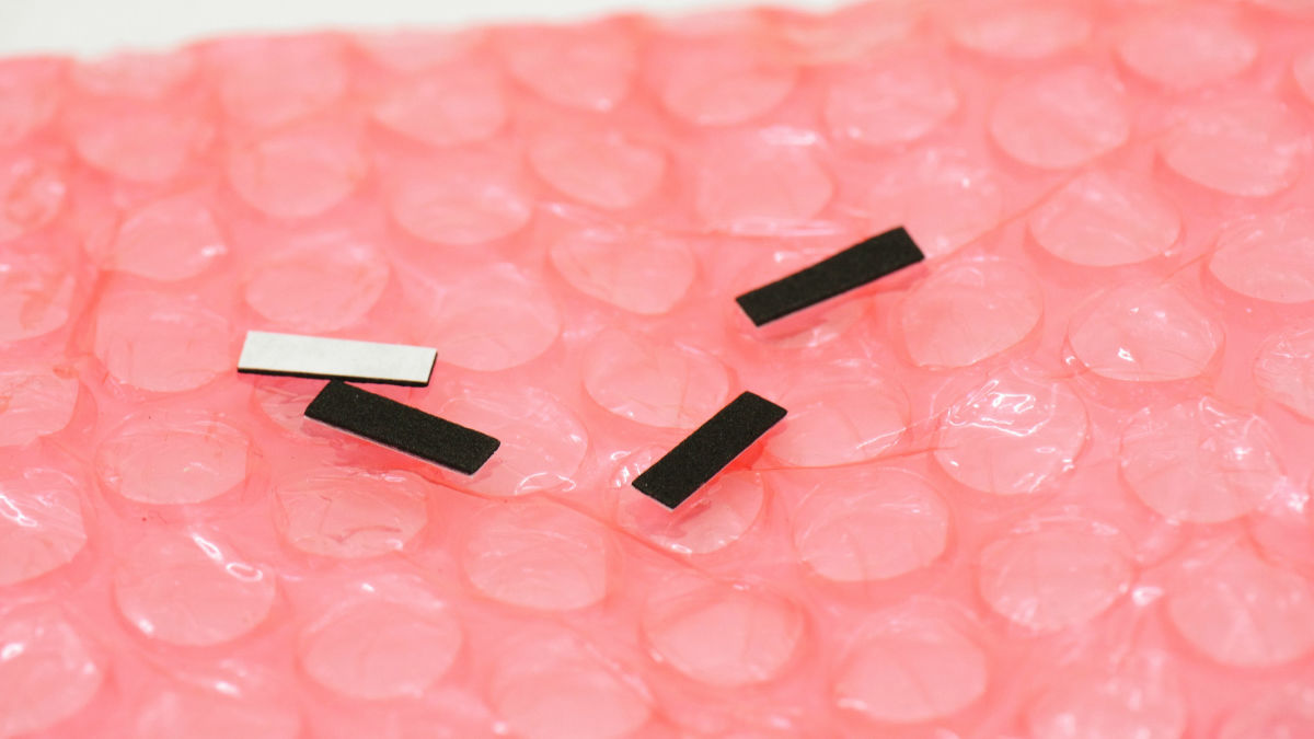
Pegs on each leg part.
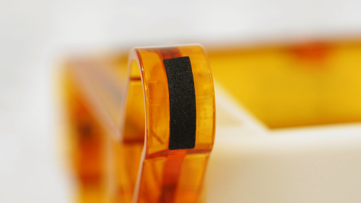
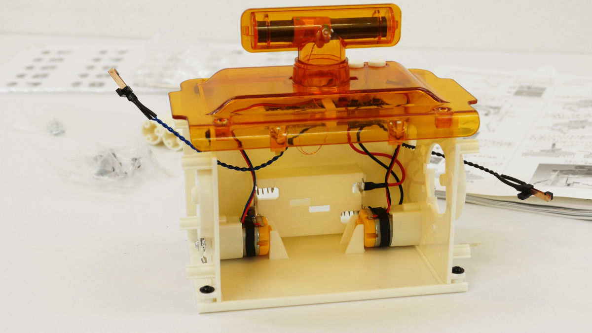
This completes the main body.
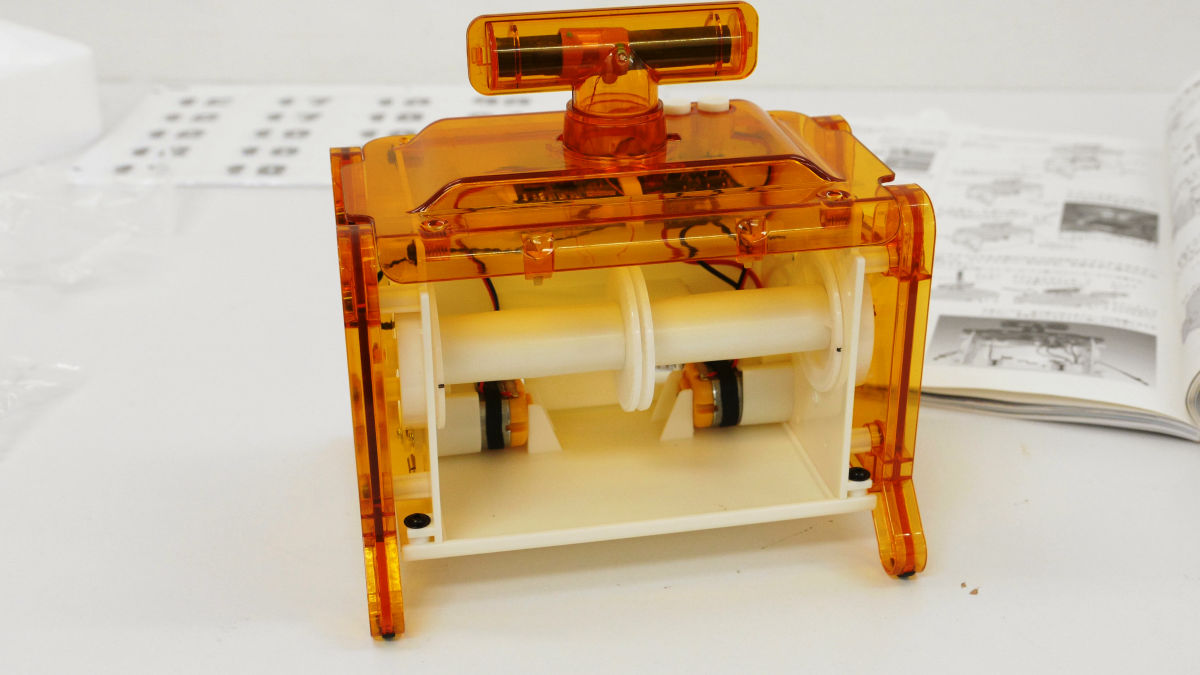
Next is the task of installing this flip.
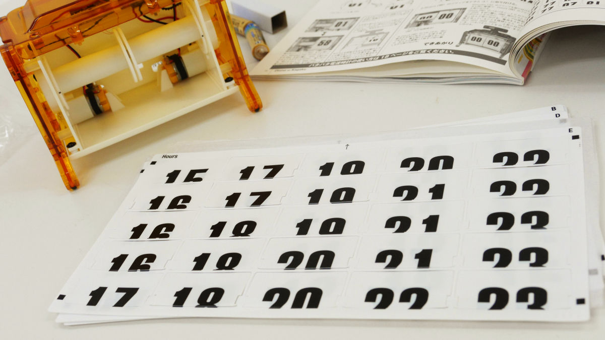
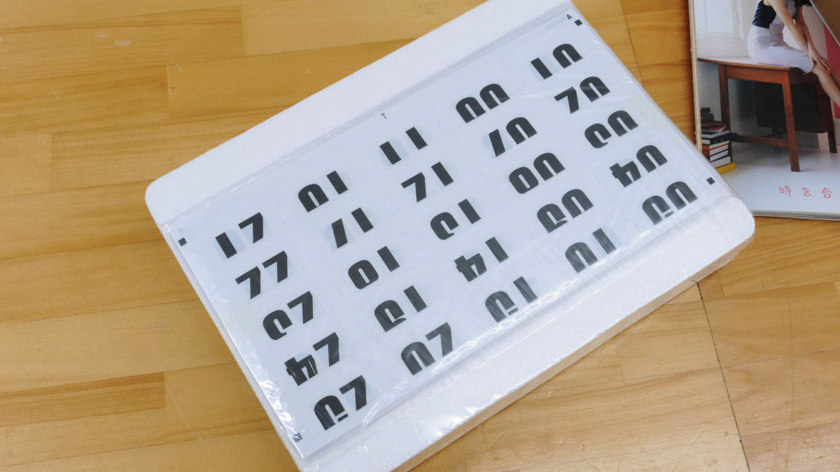
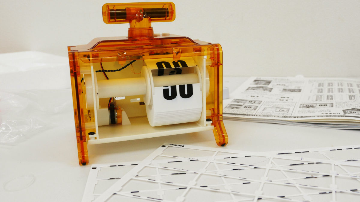
Place the sheet labeled "A" of "Minutes" with the side with "Minutes" and "A" facing up.
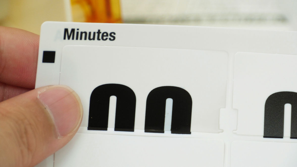
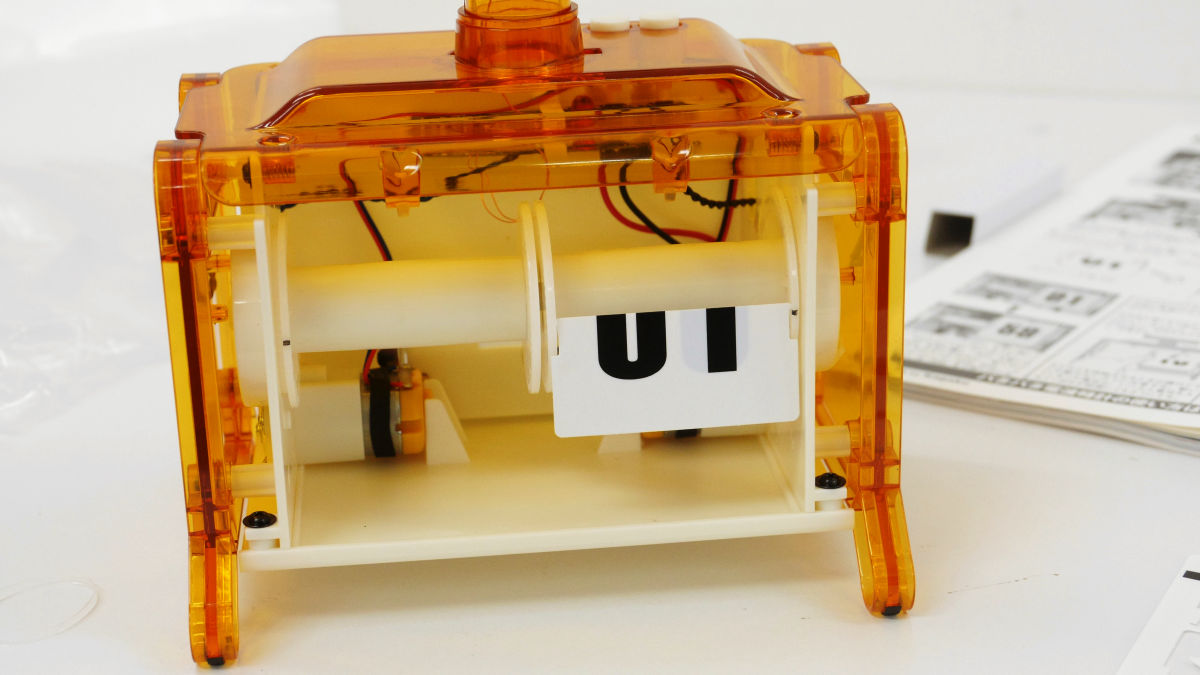
Remove the flip of "00" at the top left corner of the sheet from the sheet and place it in the hole just above the place marked with the right drum.
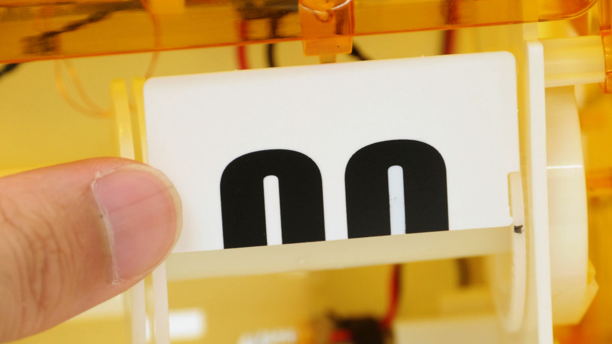
It is like this when you feel insane.

Turn the drum a little ... ...
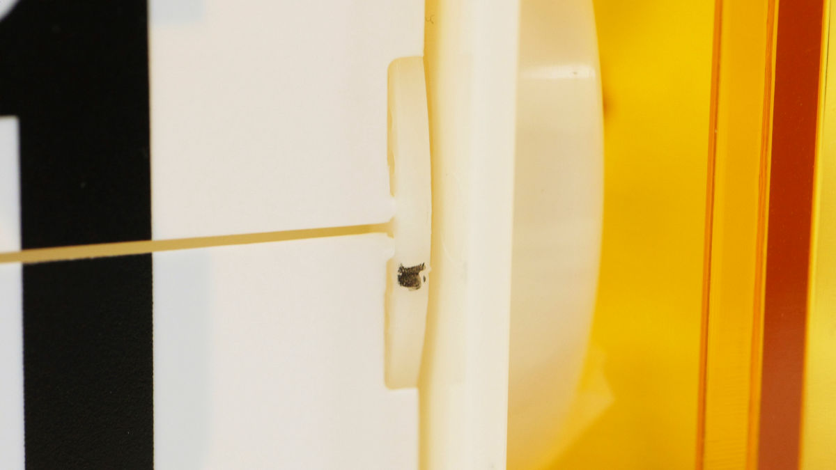
Peel off the flip of "01" under the flip of "00" and place it in the hole one above the part where you attached "00".
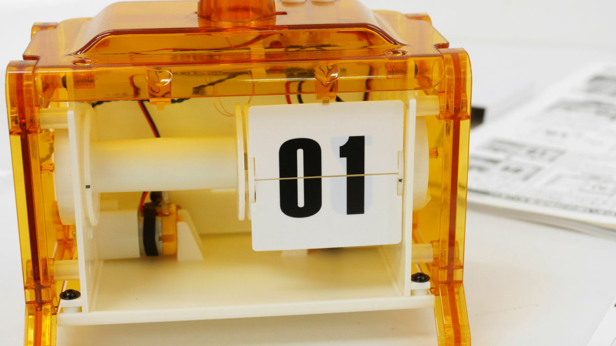
Looking like this when it is near.
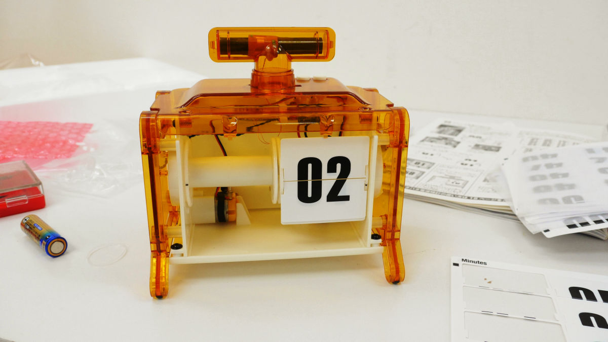
In the same way we will install "02" "03" "04" "05" ... ... and flip.
The first sheet finishes. I am exhausted because it is a detailed work.
The "Minutes" sheet will be sequenced in order of "A", "B" and "C" and the flip will be "Minutes" with the face on which the alphabet is written face up from the top left to the bottom. It will be a flip of "Hours" from the middle of the sheet of "C", but the flip of "Hours" will follow the same procedure from the hole just above the place marked with the left drum.

Fit all of the fitting in the flip. At the beginning, it is a feeling that "You can make a patchy part with this feeling", but since there are 120 flip-flops in total with the left and right drums, it will be a silent fight from the middle.
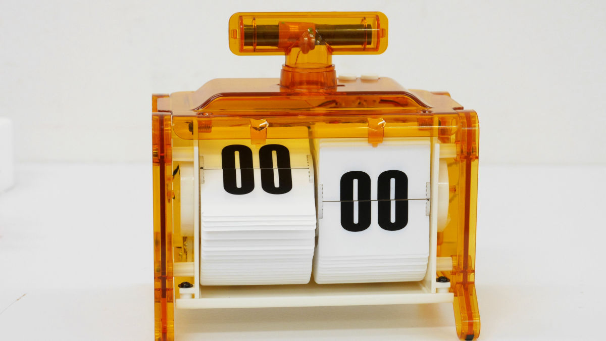
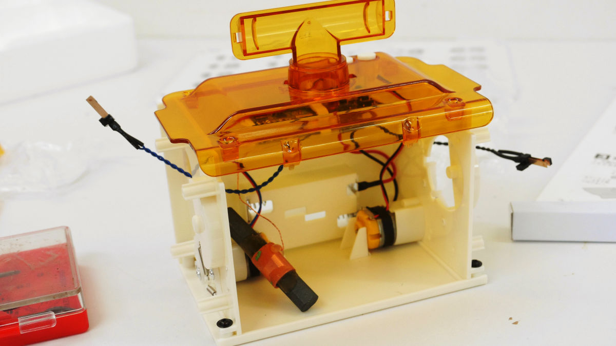
So when you put the battery in the completed patapata radio clock, it will be like the first movie.
A patapata radio clock has been completed so try inserting batteries - YouTube
After putting the battery in about 10 minutes, the patapata radio clock will display the current time.
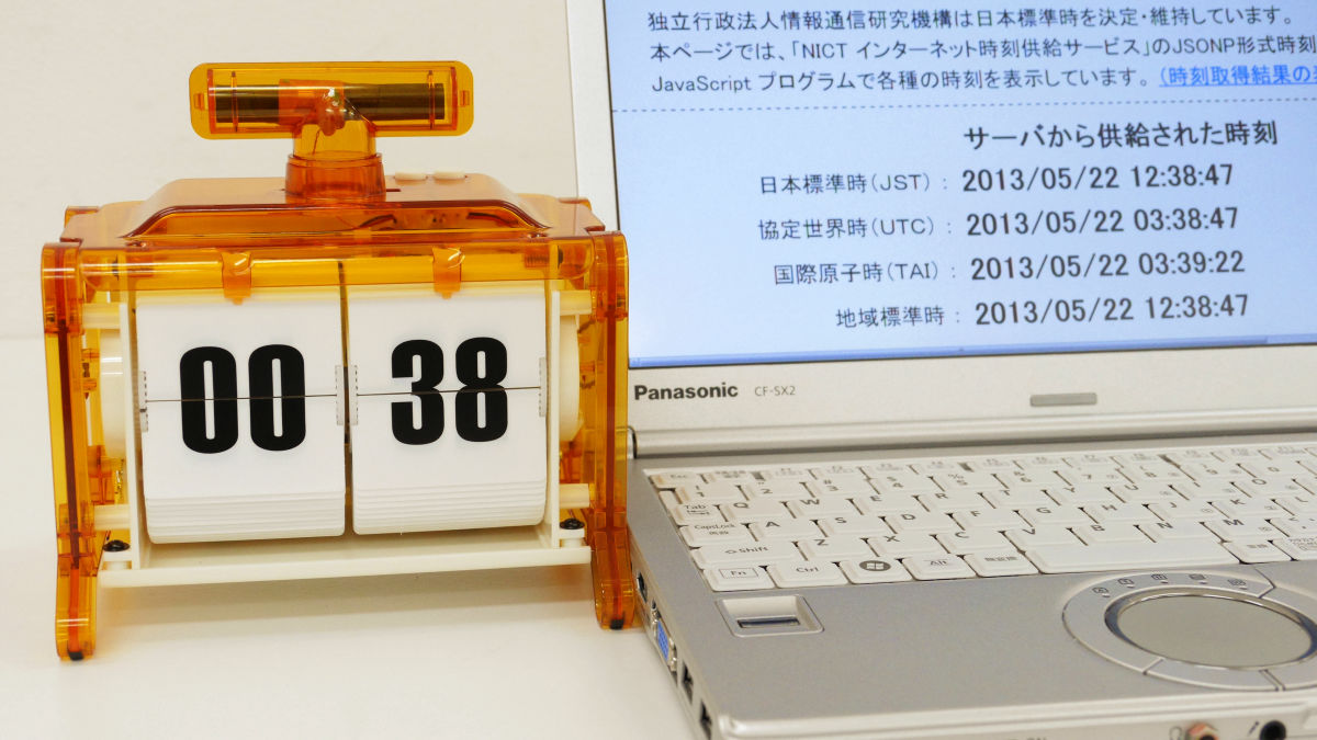
Since this LED light flashes at 5 second intervals when radio wave reception fails, please reposition the clock in a place where radio waves are good, wait for about 30 seconds after removing the battery, please push the button more than 10 times and then insert the batteries .

The science magazine for adults who can make this patapata radio clockFor Amazon it is 3500 yen including taxIt is available in.
Amazon.co.jp: Adult Science Magazine Patapata Radio Clock (Gakken Mook Adult Science Magazine Series): Adult Science Magazine Editorial Department: Books

This product isGIGAZINE summer gift articleYou can also get from.
Related Posts: