I finally connected Grabo to Raspberry Pi 5 and succeeded in outputting to the screen, so I summarized the steps.
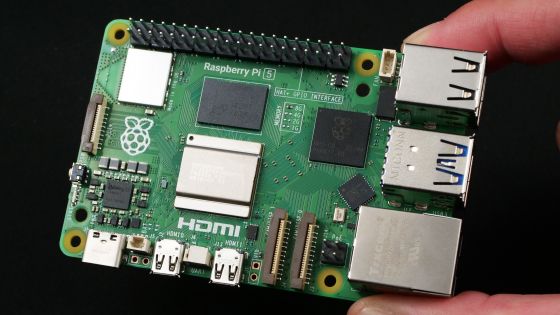
Raspberry Pi 5 supports PCIe connectivity,
Test GPU (XFX AMD Radeon RX 460 4GB GDDR5) · Issue #564 · geerlingguy/raspberry-pi-pcie-devices · GitHub
https://github.com/geerlingguy/raspberry-pi-pcie-devices/issues/564
·table of contents
◆0: Preface about technical aptitude
◆1: Parts necessary for connecting Grabo
◆2: Kernel compilation and firmware settings editing procedure
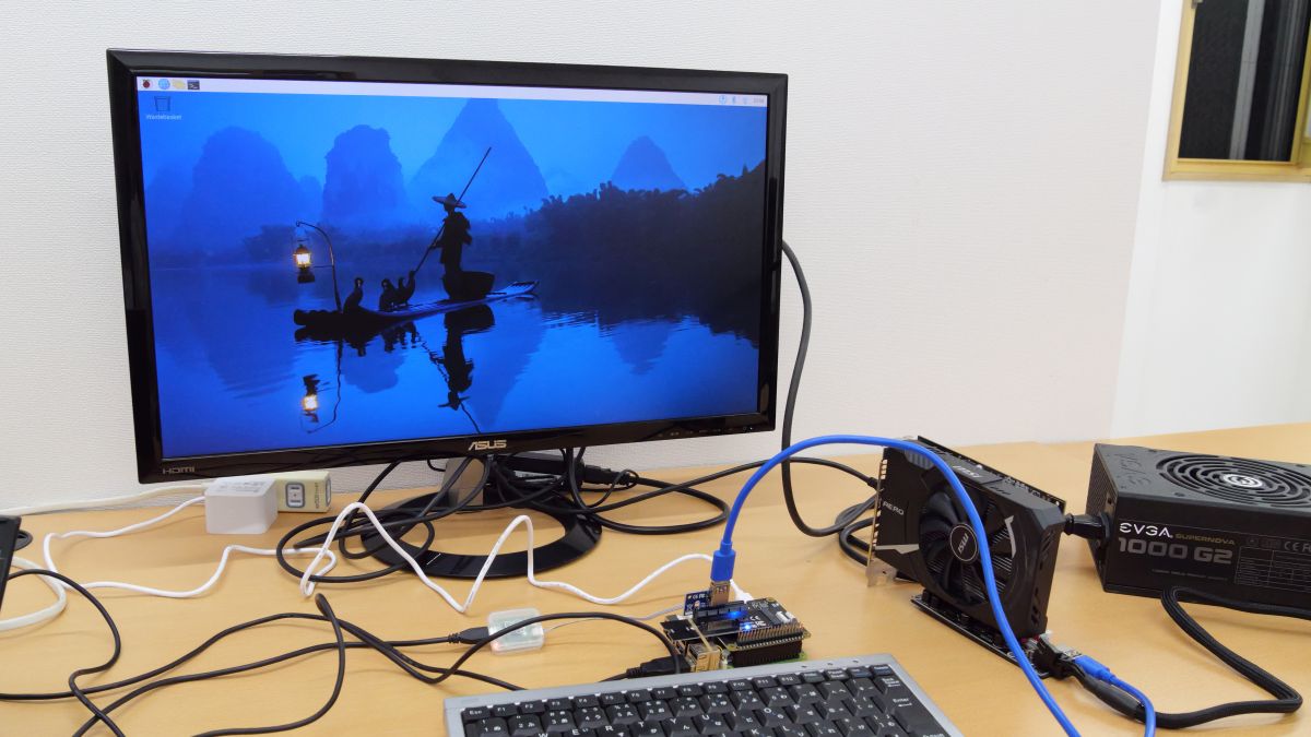
◆3: Connect the graphics board and output the screen
◆4: Start the GUI and try moving the GPU around
◆5: Some graphic boards do not work at the time of article creation.
◆6: Please tell us what you would like us to review about “Raspberry Pi 5”!
◆0: Preface about technical aptitude
The Raspberry Pi 5 used this time was sent directly to the GIGAZINE editorial department from the Raspberry Pi Foundation and has not received technical standards compliance certification. Therefore, we have submitted a notification for the ` `special system for experiments, etc. using equipment that has not obtained technical compliance .'' In addition, Raspberry Pi 5 that has already acquired technical compliance is already on sale in Japan, so general users do not need to worry about technical compliance.
◆1: Parts necessary for connecting Grabo
This time, we will connect the graphic board '
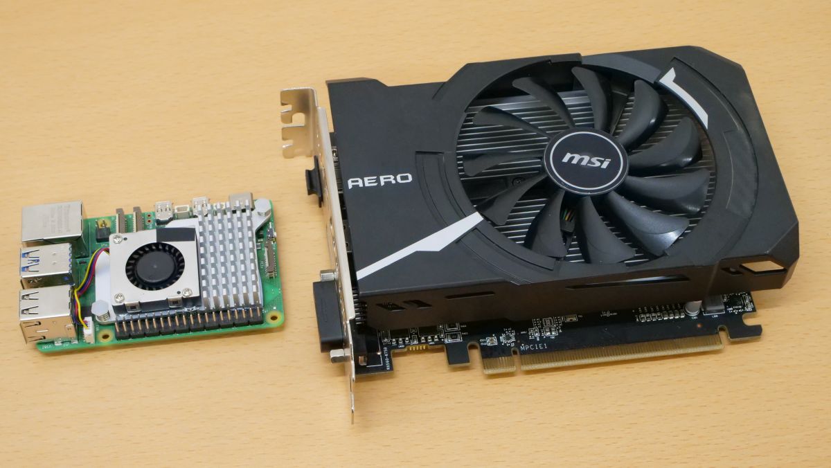
Depending on the type of PCIe expansion card that you want Raspberry Pi 5 to recognize, you may need to perform operations such as ``compiling the kernel before recognizing it'' or ``connecting a dummy card that can be recognized and then replacing it with the real card.'' You can check each procedure and required parts in the article below. This time, we will make Raspberry Pi 5 recognize the graphic board by following the steps: ``After enabling the modules required to recognize the graphic board and compiling the kernel, connect a dummy card that can be recognized and then replace it with the graphic board.''
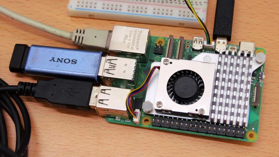
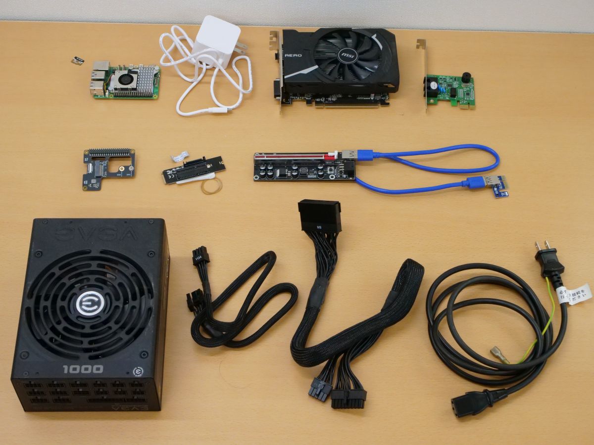
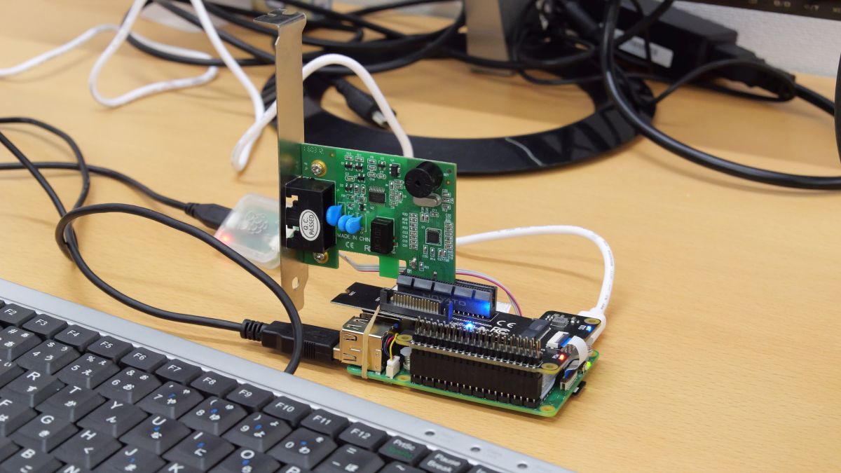
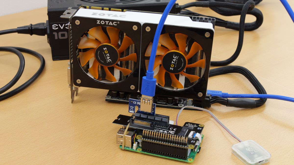
So, the parts required to make Raspberry Pi 5 recognize the graphic board are as follows. From the top left: 'microSD card with Raspberry Pi OS installed', 'Raspberry Pi 5', 'Raspberry Pi 5 power supply', 'Graphic board (Radeon RX 560 AERO ITX 4G OC)', 'Dummy card', 'PCIe and M.2 Conversion board (X1000), M.2 and PCIe x 4 conversion board (NGFFP4X-N03), Riser card for graphic board, and Auxiliary power supply and cable for graphic board. Any dummy card is OK as long as it is a card that can be recognized by Raspberry Pi 5 without any special settings. This time I am using a modem card.
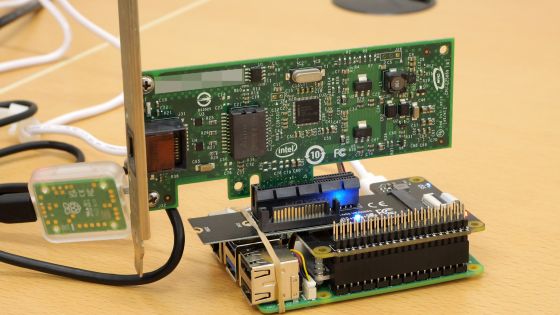
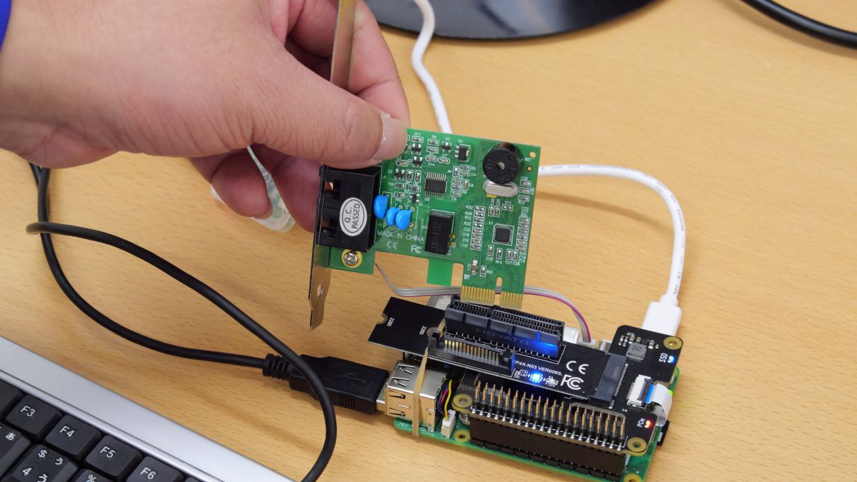
After preparing the necessary parts, attach the 'PCIe to M.2 conversion board (X1000)' and 'M.2 to PCIe x 4 conversion board (NGFFP4X-N03)' to Raspberry Pi 5.
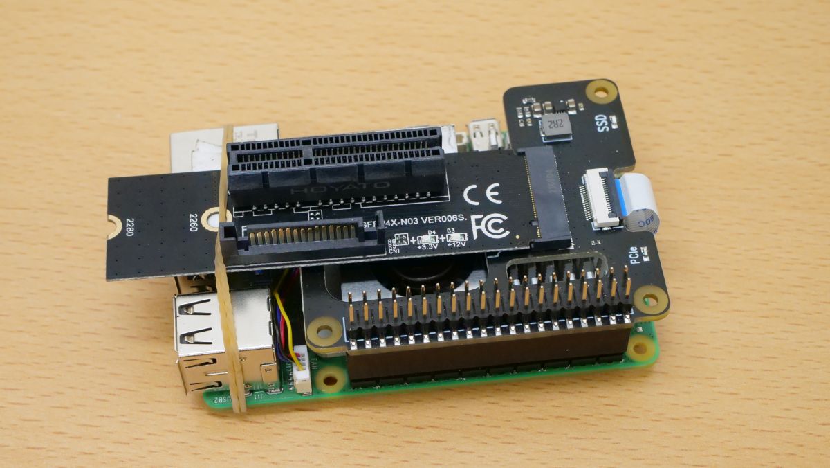
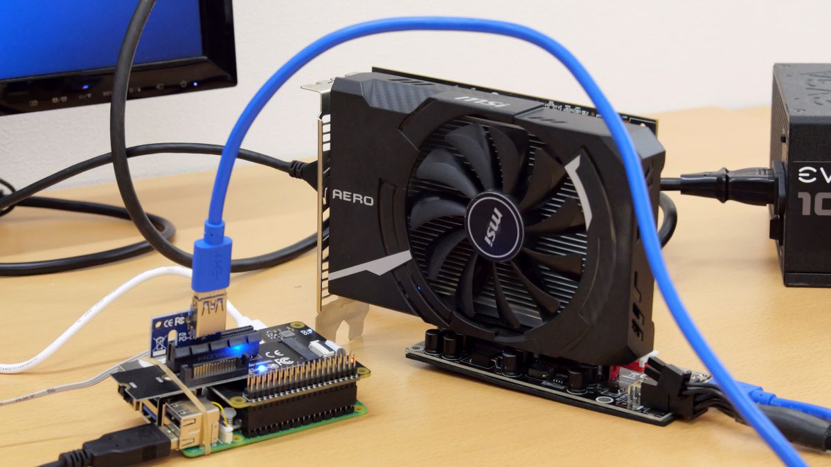
NGFFP4X-N03 has a shape that allows you to connect a graphic board, but since the 3.3V current of Raspberry Pi 5 is small, if you connect a graphic board directly to NGFFP4X-N03, it will not start up due to insufficient current. Therefore, this time I will use an ATX power supply as an auxiliary power supply and connect it to Raspberry Pi 5 via a riser card.
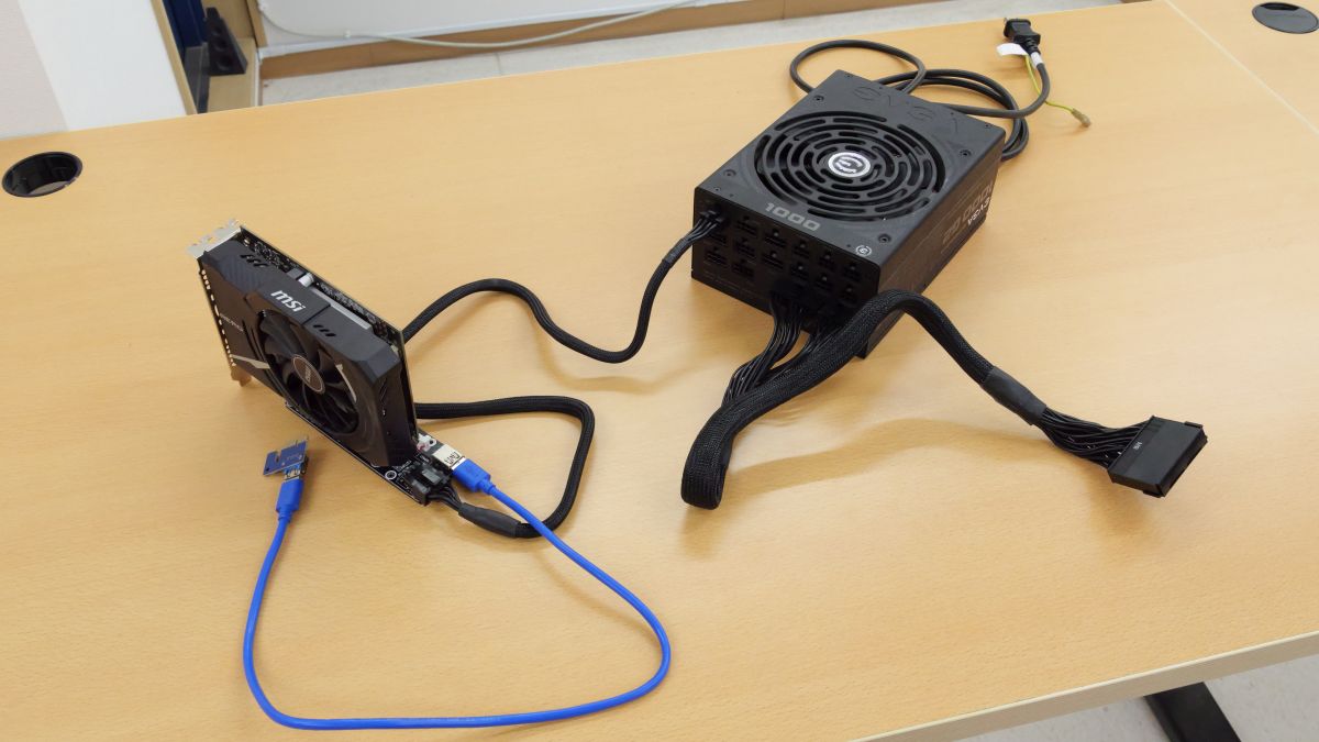
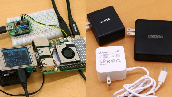
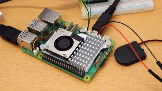
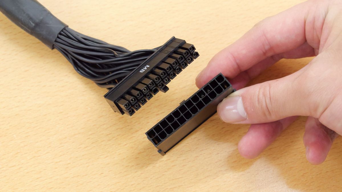
This time, we are using an ATX power supply as the auxiliary power supply, and in order to energize the power supply alone, it is necessary to short the terminals. Therefore, I connected the 'parts for turning on the power' that came with the EVGA ATX power supply to the tip of the power supply terminal. If you do not have ``parts to turn on the power,'' please refer to
◆2: Kernel compilation and firmware settings editing procedure
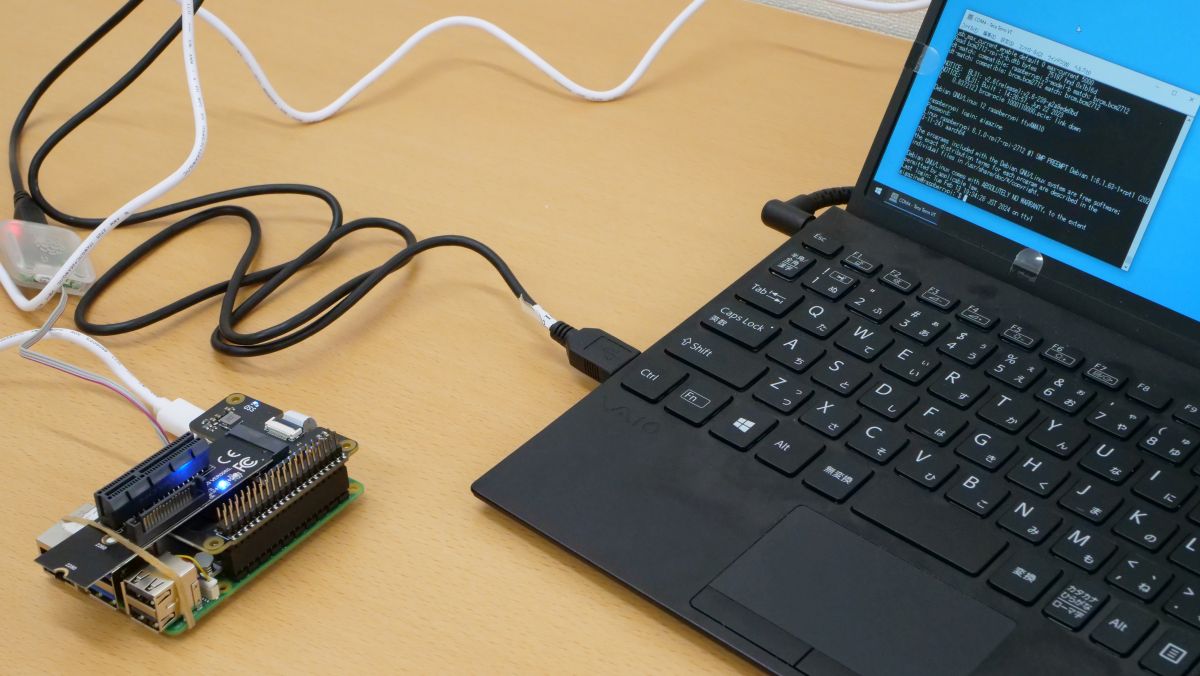
Turn on the Raspberry Pi 5, make it operational using the serial console or SSH, and proceed with compiling the kernel.
First, run the following command to obtain administrator privileges.
[code]sudo su[/code]
Next, run the following command to install the packages required for kernel compilation.
[code]apt install git bc bison flex libssl-dev make libncurses5-dev[/code]
Additionally, run the following command to install firmware for AMD GPUs.
[code]apt install -y firmware-amd-graphics[/code]
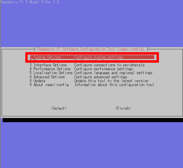
Once the package installation is complete, change the settings to display the CLI instead of the GUI at startup. First, run the following command to open the Raspberry Pi 5 management screen.
[code]raspi-config[/code]
When the management screen like the one below opens, select '1 System Options'.
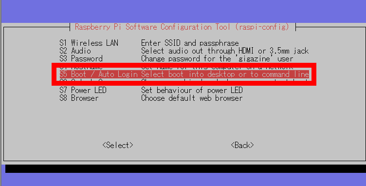
Select 'S5 Boot / Auto Login'.
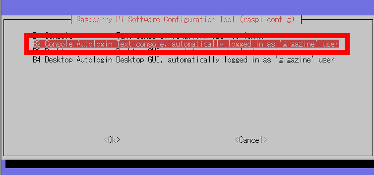
Select 'B2 Console Autologin Text console'.
Then you will be returned to the top of the management screen, so select 'Finish'.
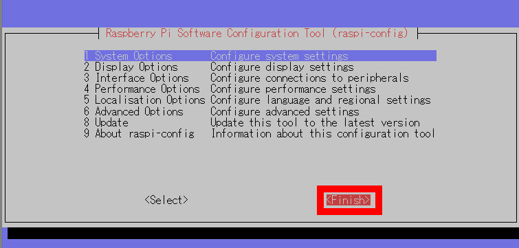
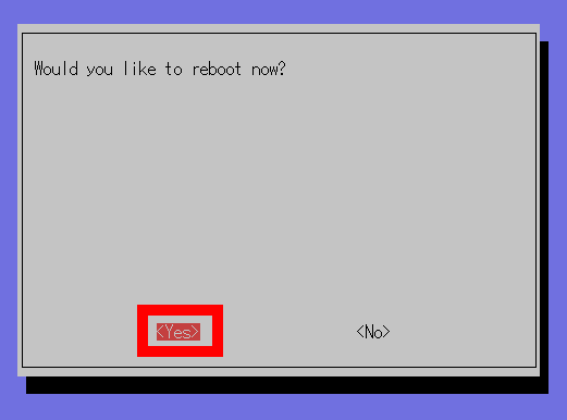
When the screen asking if you want to restart is displayed, select 'Yes' to restart the system.
After rebooting, get administrator privileges.
[code]sudo su[/code]
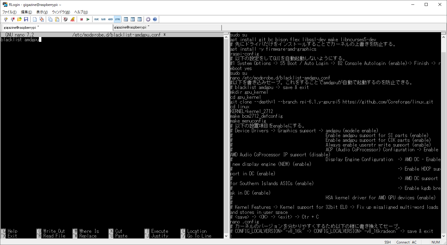
If automatic loading of kernel modules is enabled, the graphics board may not be recognized properly, so disable automatic startup of kernel modules related to AMD GPUs. First, run the following command to create a configuration file and open it in an editor.
[code]nano /etc/modprobe.d/blacklist-amdgpu.conf[/code]
Once a blank file is created, write 'blacklist amdgpu' and save it.
Next, run the following commands in order to download files and set variables required for kernel compilation. Note that the kernel is not the official kernel of the Raspberry Pi project, but a third party's own custom kernel.
[code]mkdir gpu_kernel[/code]
[code]cd gpu_kernel[/code]
[code]git clone --depth=1 --branch rpi-6.1.y-gpu-pi5 https://github.com/Coreforge/linux.git[/code]
[code]cd linux[/code]
[code]KERNEL=kernel_2712[/code]
[code]make bcm2712_defconfig[/code]
Next, run the following command to open the kernel compilation settings screen to specify the required modules.
[code]make menuconfig[/code]
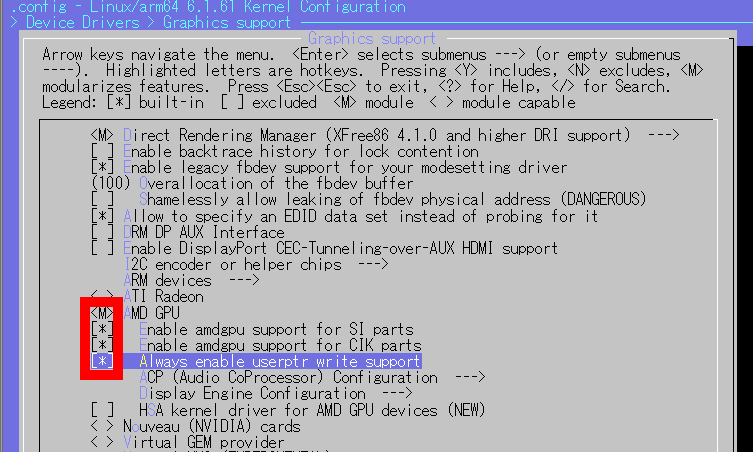
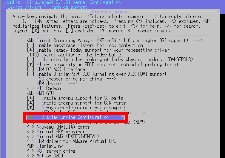
When the settings screen opens, follow the menu in the order of 'Device Drivers' and 'Graphics support', and set 'AMD GPU' to 'M (module)'. Furthermore, enable 'Enable amdgpu support for SI parts', 'Enable amdgpu support for CIK parts', and 'Always enable userptr write support'.
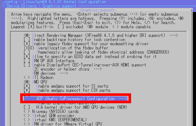
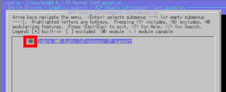
Next, select 'ACP (Audio CoProcessor) Configuration'.
After enabling 'Enable AMD Audio CoProcessor IP support', press the Esc key to return to the previous screen.
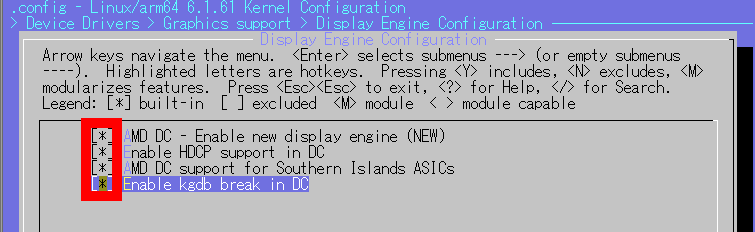
Select 'Display Engine Configuration'.
After enabling 'AMD DC - Enable new display engine (NEW)', 'Enable HDCP support in DC', 'AMD DC support for Southern Islands ASICs', and 'Enable kgdb break in DC', press the Esc key and select the previous one. back to the screen.
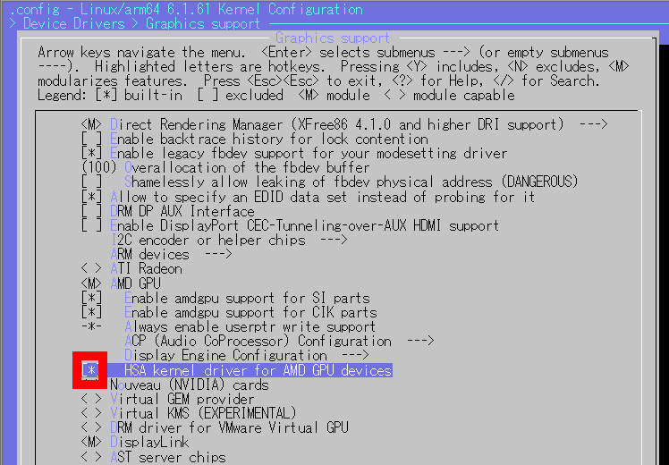
Furthermore, enable 'HSA kernel driver for AMD GPU devices' and press the Esc key to return to the previous screen.
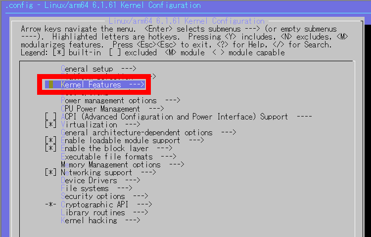
Select 'Kernel Features'.
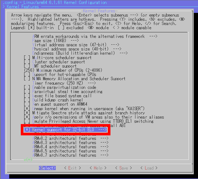
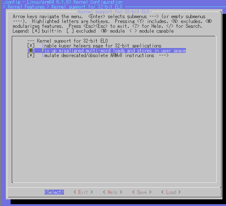
Select 'Kernel support for 32bit EL0'.
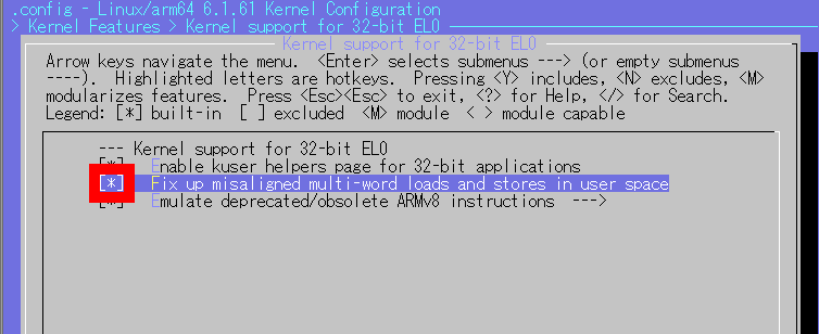
After enabling 'Fix up misaligned multi-word loads and stores in user space', select 'Save'.
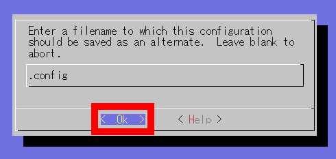
When the file name input screen is displayed, select 'Ok' without entering anything.
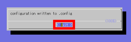
Select 'Exit'.
When you return to the top page of the management screen, close the management screen with 'Ctrl + C'.
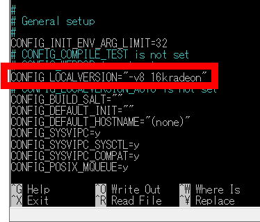
Next, run the following command to open the configuration file to rewrite the kernel version name.
[code]nano.config[/code]
Rewrite the part marked 'CONFIG_LOCALVERSION='○○○○' with an easy-to-understand name. This time, it was written as 'CONFIG_LOCALVERSION='-v8_16k', so I changed it to 'CONFIG_LOCALVERSION='-v8_16kradeon' and saved it.
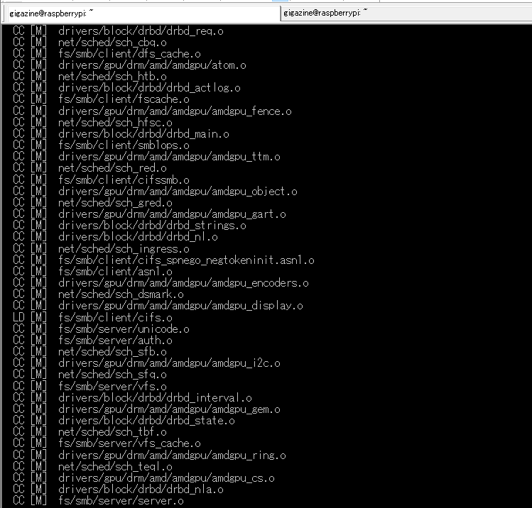
After rewriting the version name, run the following command to compile the kernel.
[code]make -j4 Image.gz modules dtbs[/code]
While the kernel is being compiled, the progress will be displayed in a staggered manner as shown below. Please wait as it will take about an hour for the compilation to complete.
Once the compilation is complete, run the following command to install the kernel module.
[code]make modules_install[/code]
Next, run the following commands in order to copy the necessary files.
[code]cp arch/arm64/boot/dts/broadcom/*.dtb /boot/firmware/[/code]
[code]cp arch/arm64/boot/dts/overlays/*.dtb* /boot/firmware/overlays/[/code]
[code]cp arch/arm64/boot/dts/overlays/README /boot/firmware/overlays/[/code]
[code]cp arch/arm64/boot/Image.gz /boot/firmware/$KERNEL.img[/code]
Next, execute the following commands in order to install the library 'memcpy_unaligned.c' required to start the GUI.
[code]wget https://gist.githubusercontent.com/Coreforge/91da3d410ec7eb0ef5bc8dee24b91359/raw/b4848d1da9fff0cfcf7b601713efac1909e408e8/memcpy_unaligned.c[/code]
[code]gcc -shared -fPIC -o memcpy.so memcpy_unaligned.c[/code]
[code]mv memcpy.so /usr/local/lib/memcpy.so[/code]
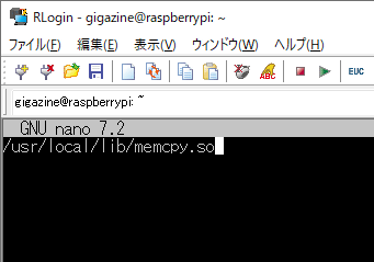
Next, create a configuration file that allows 'memcpy' to be loaded at system startup. First, run the following command.
[code]nano /etc/ld.so.preload[/code]
Once a blank file is created, write '/usr/local/lib/memcpy.so' and save it.
Additionally, to explicitly enable PCIe connectivity, edit the firmware configuration file by running the following command:
[code]nano /boot/firmware/config.txt[/code]
Once the configuration file opens, add the following two lines at the end: Raspberry Pi 5 is said to be compatible with PCIe Gen2 according to the specifications, but by writing 'dtparam=pciex1_gen=3' in the firmware configuration file, high-speed connection with PCIe Gen3 is possible.
dtparam=pciex1
dtparam=pciex1_gen=3
Next, run the following command to rewrite the EEPROM.
[code]rpi-eeprom-config --edit[/code]
When the editing screen opens, rewrite the contents of the file as shown below and save it.
[all]
BOOT_UART=1
POWER_OFF_ON_HALT=1
WAKE_ON_GPIO=1
BOOT_ORDER=0xf41
PCIE_PROBE=1
Once the settings are complete, run the following command to restart the system.
[code]reboot[/code]
After rebooting, get administrator privileges.
[code]sudo su[/code]
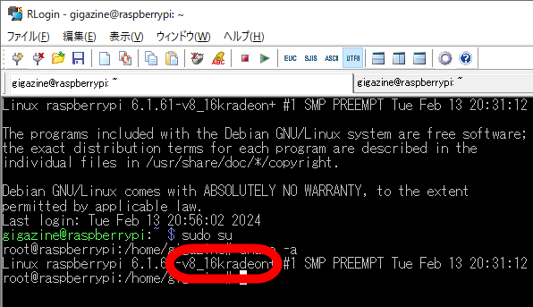
Run the following command to check the kernel version.
[code]uname -a[/code]
If the kernel version name is as configured, the kernel compilation and installation was successful. This time, '-v8_16kradeon' was displayed correctly.
After confirming that the kernel has been installed correctly, execute the following command to shut down the system.
[code]halt[/code]
◆3: Connect the graphics board and output the screen
Now that the kernel compilation and firmware preparations are complete, it's time to connect the graphics board to Raspberry Pi 5. The general flow of connection is ``First connect the dummy card and make it recognized, then replace the dummy card with the graphic board and make it recognized.'' The specific steps are as follows.
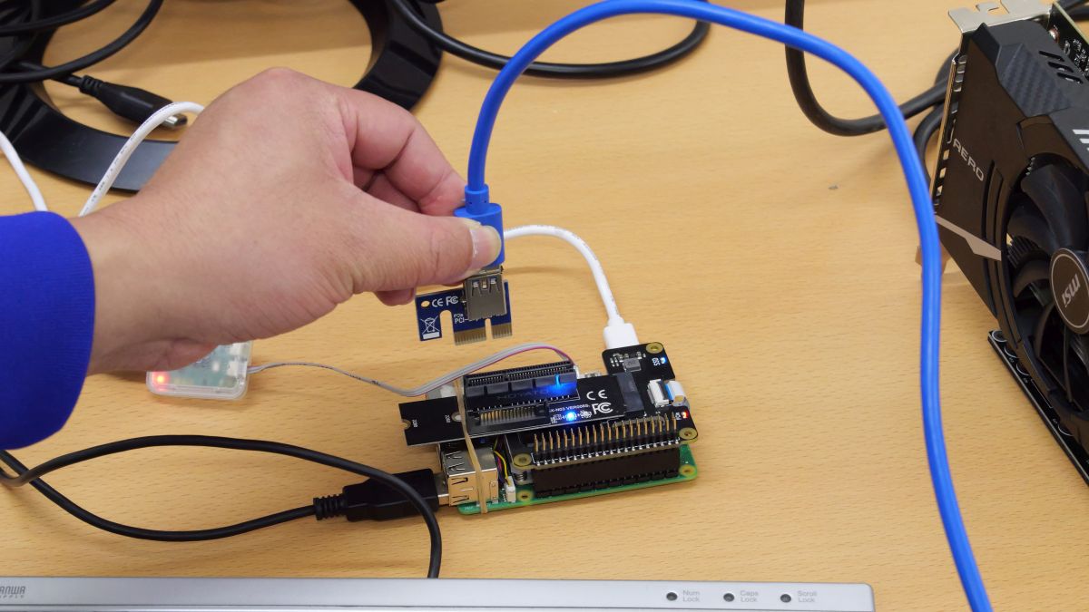
First, attach the dummy card to Raspberry Pi 5 and turn it on.
Next, obtain administrator privileges.
[code]sudo su[/code]
Execute the following command to check whether Raspberry Pi 5 can recognize the dummy card.
[code]lspci[/code]
We confirmed that the card was recognized with the name 'Communication controller: LSI Corporation Device'.

Then, run the following command to check the connection information details.
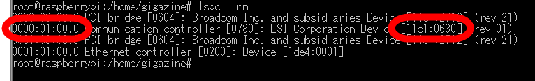
[code]lspci -nn[/code]
The command execution result looks like this. Make a note of '0000:01:00.0' at the beginning of the line containing 'Communication controller: LSI Corporation Device' and the four-digit number '0630' at the end. This '0000:01:00.0' indicates the location of the device as seen from the PCI bus, and '0630' indicates the device ID.
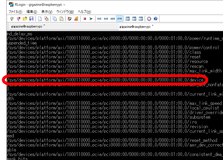
Next, in order to manipulate the connection status of the dummy card, execute the following command to find the directory to be manipulated.
[code]find /sys/devices | grep 0000:01:00.0[/code]
The directories displayed in a row in the search results are the target directories. This time, you can see that '/sys/devices/platform/axi/1000110000.pcie/pci0000:00/0000:00:00.0/0000:01:00.0' is the directory to be operated on. To confirm that the target directory is correct, note down the path of the file named 'device' in the target directory. This time, note '/sys/devices/platform/axi/1000110000.pcie/pci0000:00/0000:00:00.0/0000:01:00.0/device'.
Next, run the following command to check the contents of the file.
[code]cat /sys/devices/platform/axi/1000110000.pcie/pci0000:00/0000:00:00.0/0000:01:00.0/device[/code]
It is OK if the contents of the file include the device location and device ID. The execution result this time is as follows, and it contains the device location '0000:01:00.0' and the device ID '0630', so continue the operation as is.
0/0000:01:00.0/device
0x0630
Next, execute the command below to write 1 to the 'remove' file in the target directory to remove the dummy card from the system using software.
[code]echo '1'> /sys/devices/platform/axi/1000110000.pcie/pci0000:00/0000:00:00.0/0000:01:00.0/remove[/code]
Run the following command to check the device connection status.
[code]lspci[/code]
You can see that the removal was successful because 'Communication controller: LSI Corporation Device' is not included in the execution results of 'lspci'.
Next, physically remove the dummy card from the Raspberry Pi 5.
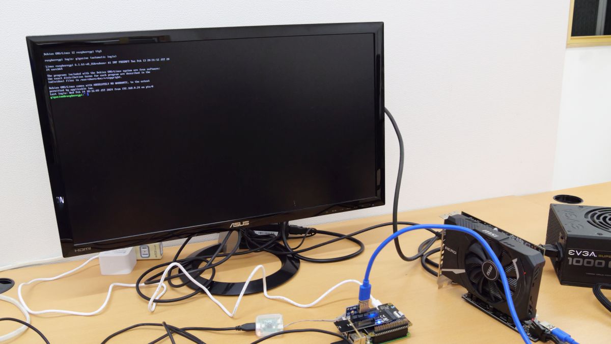
Then connect the graphics board to Raspberry Pi 5. Also, connect the display and power supply.
After connecting the graphics board, write '1' to the 'rescan' file located one level above the target directory and rescan the device. The commands to be executed are as follows.
[code]echo '1'> /sys/devices/platform/axi/1000110000.pcie/pci0000:00/0000:00:00.0/rescan[/code]
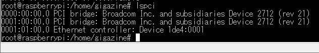
Next, run the following command to check the device connection status.
[code]lspci[/code]
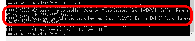
The execution result looks like this. The fact that it says 'Radeon RX 550 640SP / RX 560/560X' indicates that the graphics board is recognized.
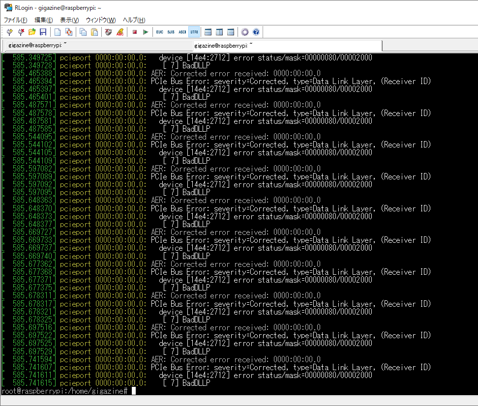
Additionally, try running ``dmesg'' to check the kernel logs.
[code]dmesg[/code]
The execution result looks like this. If an error related to 'AMD GPU' is output, it is likely that the module has failed to load, so you will need to recompile the kernel from the beginning. This time, the error did not occur, so it seems to have been successful.
It seems that the graphics board has been successfully recognized, so execute the following command to load the kernel module for AMD GPU.
[code]modprobe amdgpu[/code]
Then, the CLI screen should appear on the display. Now you can connect the graphics board to Raspberry Pi 5 and output the screen.
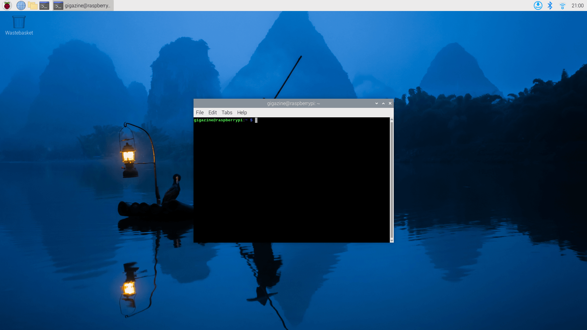
◆4: Start the GUI and try moving the GPU around
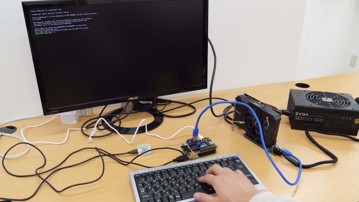
Since the screen output was successful, we will proceed with the operation from here using the keyboard connected to the Raspberry Pi 5.
Execute the following command to start the GUI.
[code]wayfire-pi[/code]
After waiting for a while, the GUI will start. At the time of writing the article, there is a problem that the mouse pointer is not displayed, but the mouse is recognized, so you can perform operations such as ``bring up the right-click menu'' and ``try dragging on the screen.'' If you know the position of the mouse pointer, you can operate it with a mouse, although it is difficult to say it is practical.
Next, install the 3D benchmark software ``glmark2'' and the operating status monitoring software ``radeontop'' to move the graphic board. First, start the terminal using your mouse and keyboard.
Obtain administrator privileges.
[code]sudo su[/code]
Install 'glmark2' and 'radeontop' by running the following commands in order.
[code]apt install glmark2[/code]
[code]apt install -y libdrm-dev libncurses-dev libxcb-dri2-0-dev[/code]
[code]git clone https://github.com/clbr/radeontop.git[/code]
[code]cd radeontop[/code]
[code]make[/code]
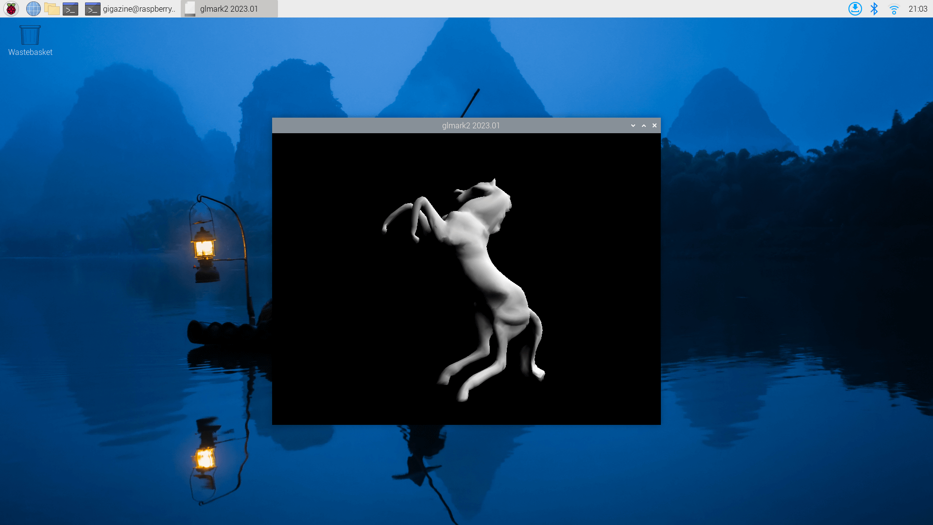
Once the installation is complete, run 'glmark2' to make the graphics board perform 3D processing.
[code]glmark2[/code]
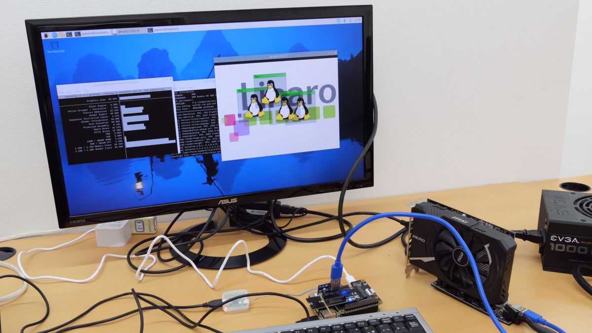
The execution screen of 'glmark2' looks like this.
Furthermore, open another terminal and execute the following commands in order.
[code]cd radeontop[/code]
[code]./radeontop[/code]
Now you can monitor the operating status while performing CG processing on the graphics board.
◆5: Some graphic boards do not work at the time of article creation.
I tried to see if I could also recognize a graphics board equipped with an NVIDIA GPU, but even if I enabled the module that supports the NVIDIA GPU and compiled the kernel, an error occurred and it could not be recognized. There is also information on the Internet that states that
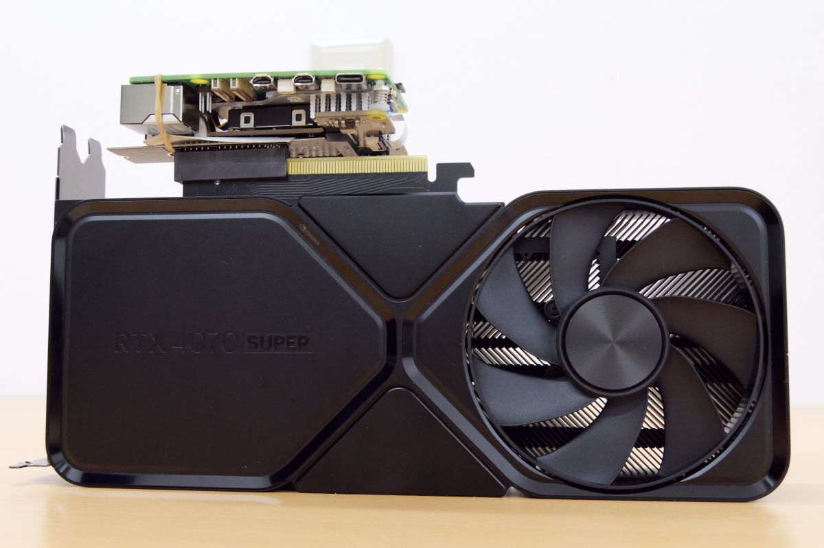
By the way, when I first learned that ``Raspberry Pi 5 supports PCIe connection'', I fantasized about connecting a graphic board that is overwhelmingly larger than Raspberry Pi 5 and outputting screen output! However, it was not possible due to problems such as ``Unable to recognize NVIDIA GPU'' and ``Raspberry Pi 5's 3.3V current is low.''
◆6: Tell us what you would like us to review about “Raspberry Pi 5”!
Please use the link below to tell us the points you would like us to try because you are actually using it, such as 'Try what happens when you do this!', 'Can you do this?', and 'What will happen in this situation?' It's okay if the content overlaps with someone else's, but the more you have, the more helpful it will be for you to understand that this is what you're concerned about. And it will be reflected in your next review article creation!
• Discord | 'Raspberry Pi 5 has arrived at the GIGAZINE editorial department, so I'm going to review it, but what do you want to know? ' | GIGAZINE
Related Posts: