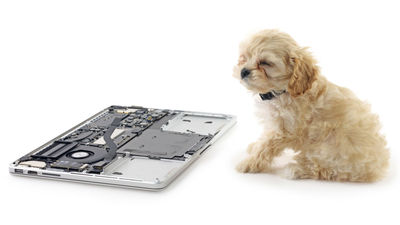
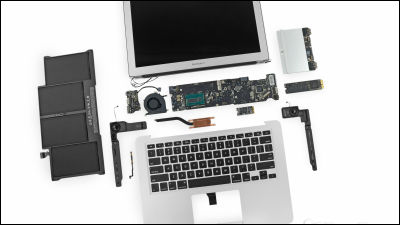
Disassembly report of "MacBook Pro Retina display model" appeared in iFixit

On October 23, at Apple's announcement event, MacBook Pro with Retina display was announced. The major change from the past model is that Intel's fourth-generation core "Haswell" has a processing speed as high as 90%. With such a MacBook Pro Retina display equipped model disassembly / repair professional groupIFixitAs soon as it breaks apart and publishes a photo report.
MacBook Pro 13 "Retina Display Late 2013 Teardown - iFixit
http://www.ifixit.com/Teardown/MacBook+Pro+13-Inch+Retina+Display+Late+2013+Teardown/18695/1
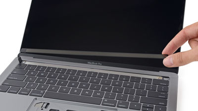
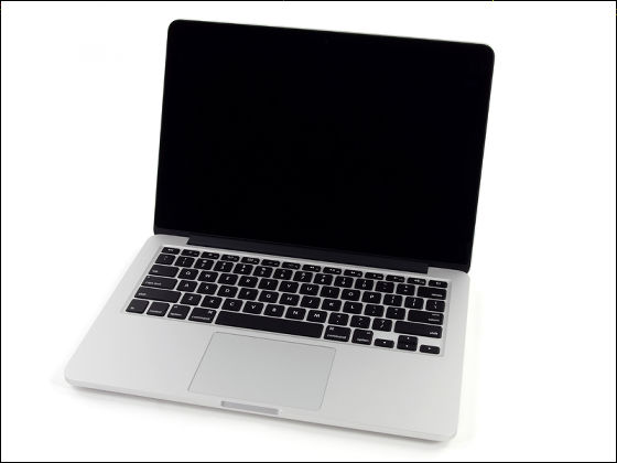
First we have a 13-inch MacBook Pro Retina display loaded model to disassemble.
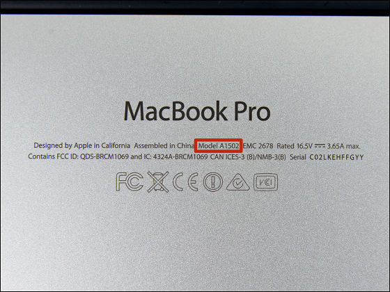
Model number is "A1502"
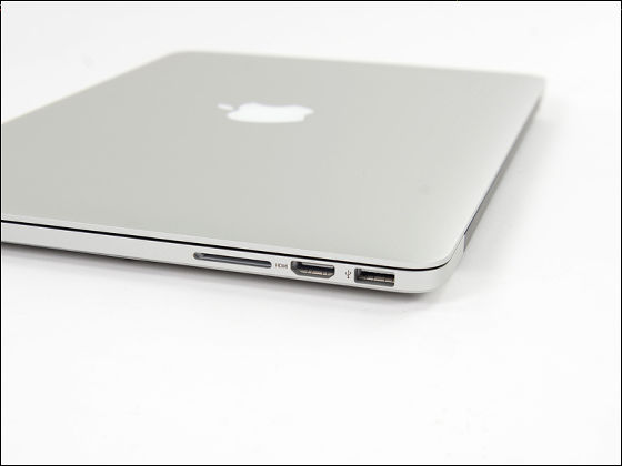
The SDXC card slot, HDMI port, USB 3.0 port are aligned on the left side facing the main unit. On the other side there is a Thunderbolt, USB port.
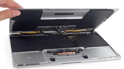
Removing the screwed bottom
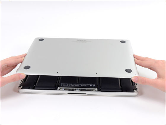
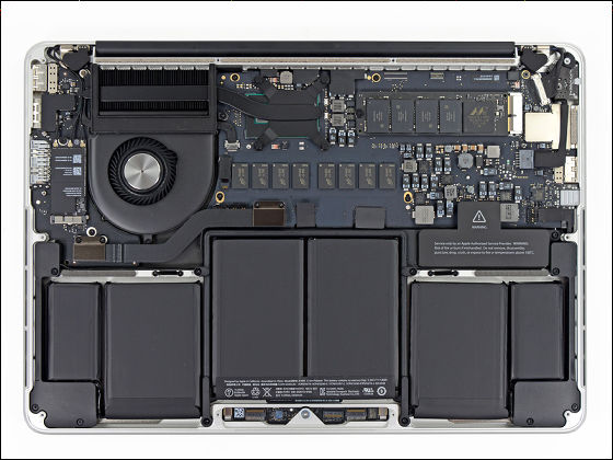
It is not SSD but HDD, the position of the fan and the type of battery are changed.
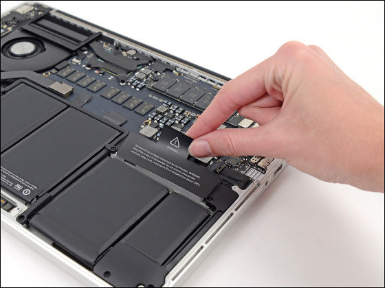
Warning label that Apple maintenance will be unavailable if you remove the battery. "Repair is more than recycling Eco-repair saves the world"IFixit with a manifest named" iFixit "will continue decomposing without worrying about it.
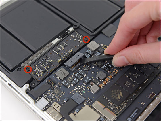
First of all, in order to prevent electric shock, remove the connector part so that the power supply of the battery does not flow.
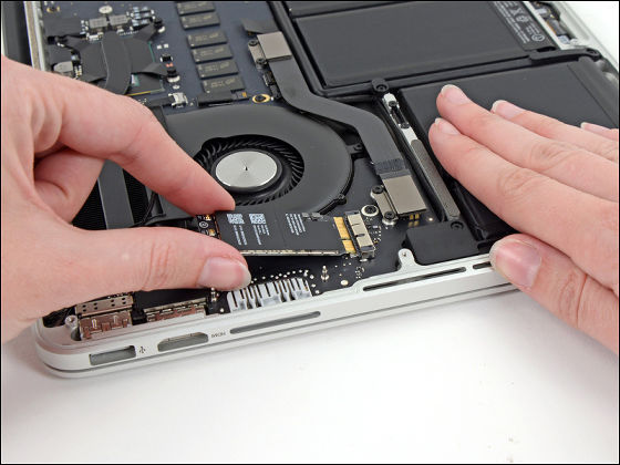
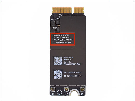
Next, disconnect the antenna cable connected to the AirPort card and pull out the AirPort card itself.
New AirPort card compatible with 802.11n / ac Wi-Fi connection "BCM 94360 CS".
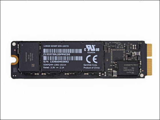
This is a 128GB SSD of SanDisk which is built-in flash storage.
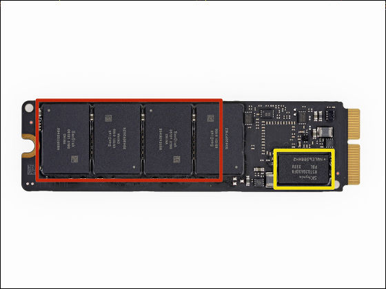
Four sheets of 16 GB "SanDisk 05131 016 G 16 GB NAND Flash" in the red frame. SK Hynix "Yellow frame"H5TQ2G63DFRDDR 3-1600.
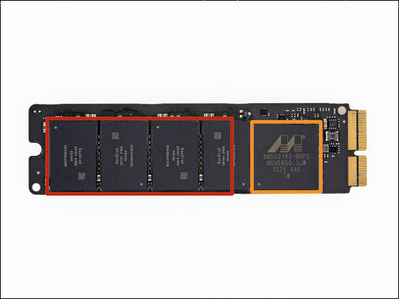
Also on the back side and is equipped with NAND Flash is four 16GB × 8 sheets = 128GB. A larger model of the capacity has 256GB and 512GB, 512GB model is upgradable and that up to 1TB. Marvell is the orange frame Semiconductor 88SS9183 SSD Controller.
Remove the I / O board cable outside the socket ......
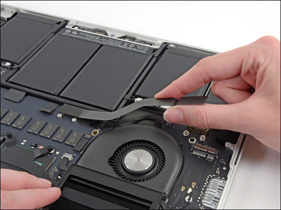
Pro Tech ScrewdriverI will disassemble the surroundings of the speaker using.
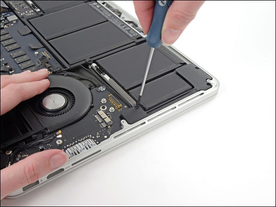
Removal of the speaker is completed. This part is a rather easy task.
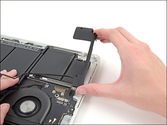
Device decomposition work pro kit located on the batteryIOpenerThere are clogged plastic picks and sticks for peeling off adhesive.
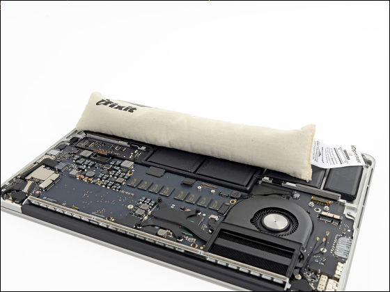
Start inserting the battery while inserting the plastic card.
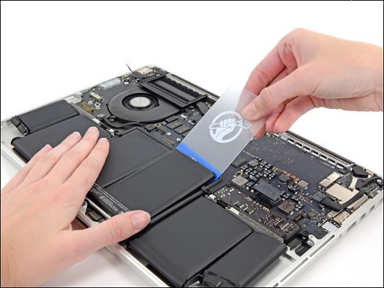
Since the adhesive is surprisingly powerful, it is difficult to remove, but the removal of the connected panel battery is completed.
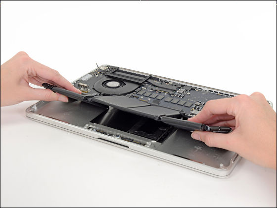
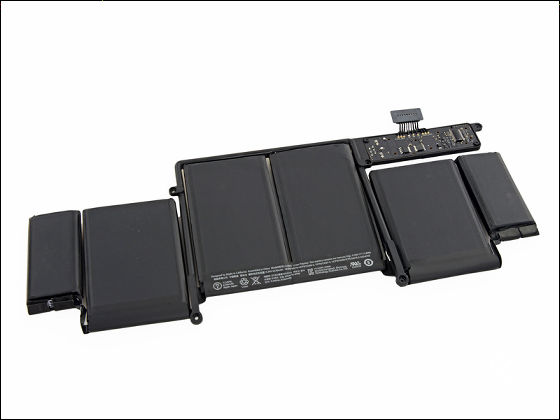
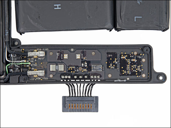
The power efficiency is greatly improved by the panel battery divided into six parts, and usually usable for 9 hours continuous use. The amount of electricity (battery capacity) is 71.8 Wh and the voltage is 11.34 V.
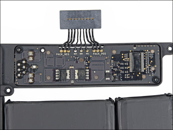
Connector part that connects the battery to the motherboard.
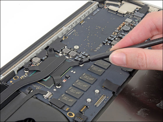
I remove the fixed part of the heat sink on the CPU with ironing.
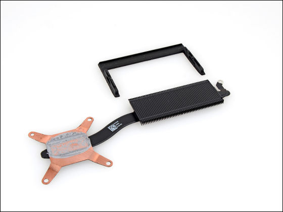
The CPU adopts Intel's Haswell processor, GPUIris, So the heat sink is larger.
The fan also got a bit bigger to fit the heat sink.
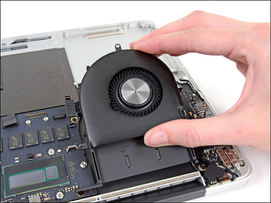
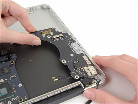
Next, remove the I / O board on the right side of the main unit under the fan.
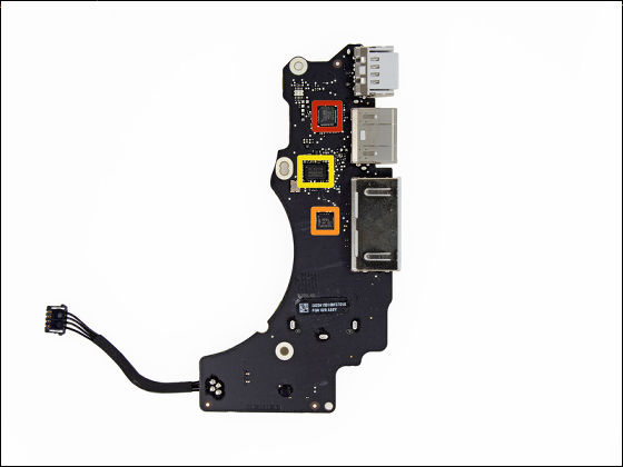
In the red frame Parade Technology "PS8401A"HDMI Jitter Cleaning Repeater is installed. Among the yellow frames are Genesys Logic "GL 3219" of SDXC card reader controller. Within the frame of orange NXP Semiconductors "PCA 9501"8-bit I / O Expander with an On-Board 2-kbit EEPROM.
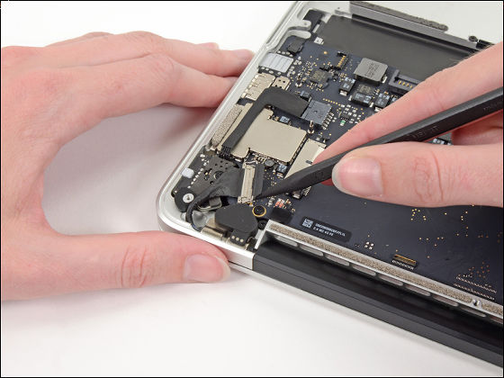
Remove the fasteners that secure the logic board (motherboard).
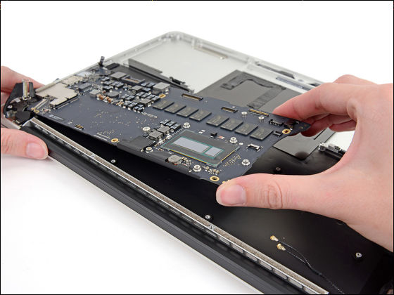
Removal of the board is also completed.
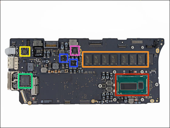
The front side of the logic board (motherboard). Among the yellow frames are Cirrus "4208-CRZ" of the HD codec, Intel controlling the Thunderbolt 2 within the frame of greenDSL 5520"Fairchild Semiconductor" DD 18 BB "220 A within two blue borders. In the frame of orange is Micron "D9PXV"4 GB (512 MB) DDR 3 L SDRAM (total 8 × 512 MB = 4 GB), Intel SR 18 A Core i 5 - 4258 U Processor is arranged in the red frame.
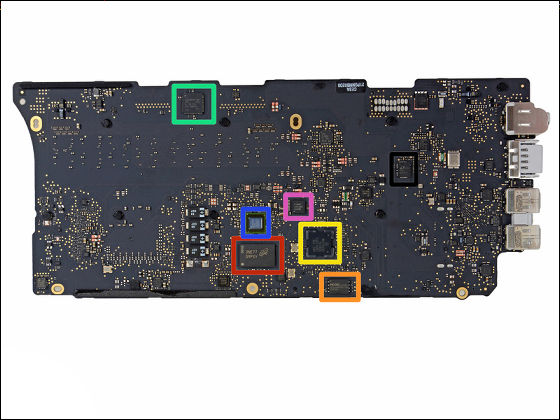
Backside. The green frame is Cypress "CY8C24794-24LTXI"Programmable System-on-Chip, Broadcom BCM 15700 A 2 in the blue frame, Micron" D 9 PXV "in the red frame 4 GB (512 MB) DDR 3 L SDRAM. P13WVR 12612NEE in pink frame, Texas Instruments Stellaris LM4FS1EH Microcontroller in yellow frame and MXIC MX25L 6406E 64 Mbit bit CMOS Serial Flash in orange frame.
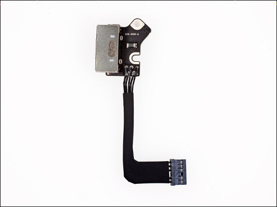
Port section of MagSafe 2 which is a new standard of charging connector changed from new model.
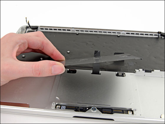
Next, remove the plate inside the trackpad. This was the same as the 2012 version.
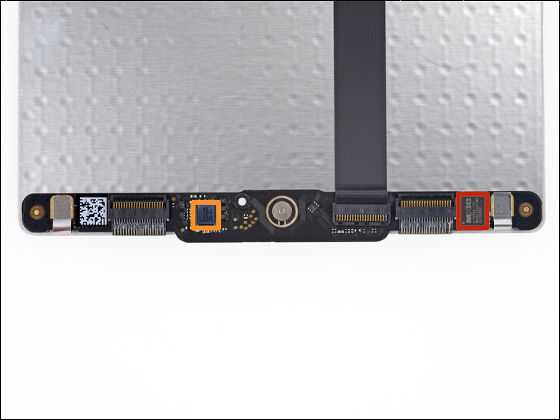
IC part of the track pad. Broadcom which is the touch screen controller same as the one used for iPhone 5 in the orange frameBCM 5976Discovered. In the red frame are Macronix 'MX25L 2006 E' 16 Mbit bit CMOS Serial Flash.
Remove the black rubber hinge covering the three screws fixing the display.
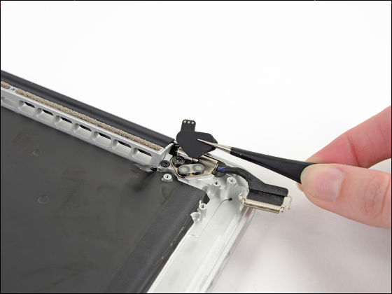
I removed the screws and set up the main unit.
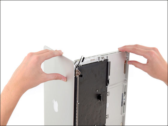
The removal of the Retina display is also completed. This completes all dismantling work.
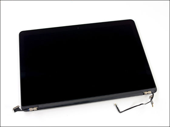
MacBook Pro Retina The repair difficulty of the display model is ranked as "1", which is the most difficult, so if you decompose it requires extreme caution and preparedness.

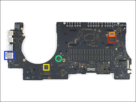
Incidentally,15 inch MacBook Pro Retina display model decomposition reportIFixit has released it, "Since the headphone jack is soldered to the logic board (within the frame of the blue), it is easy to break down even if it is used normally, and for repair it costs $ 1000 (about 100,000 yen ) It indicates concern that repair fee is needed nearby.
Related Posts:
in Hardware, Posted by darkhorse_log
