I tried to combine a lot of optical line termination devices using Allied Telesis's switch that can create VLAN

In Internet services using optical lines, it is necessary to install a
Normally, a router that relays multiple networks is connected to the terminating device, but it is also possible to connect a server directly to the terminating device without using a router and connect to the Internet using the PPPoE protocol. In that case, the network configuration is as follows.
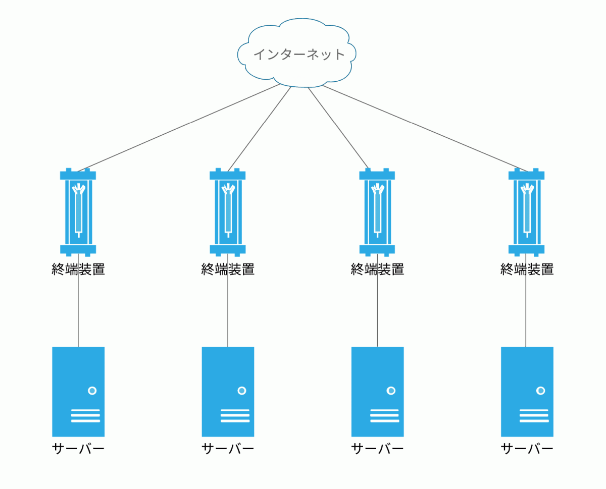
However, in this configuration, if one terminal device fails, the server connected to it will not be able to connect to the Internet.
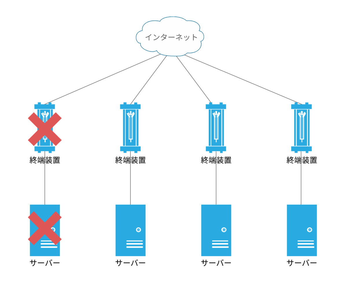
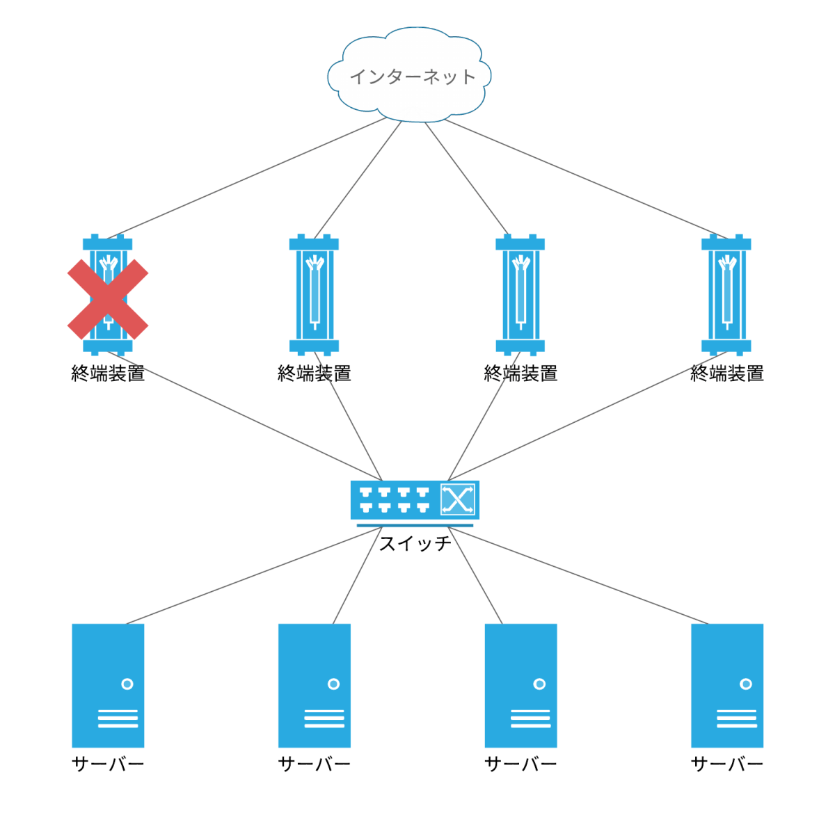
Use a switch to make the line between the terminator and the server
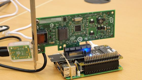
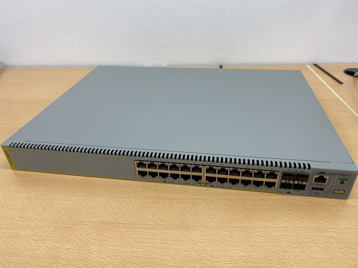
The switch used is Allied Telesis's x510 series.
Switch | CentreCOM x510 Series AT-x510-28GTX

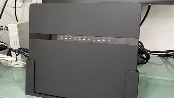
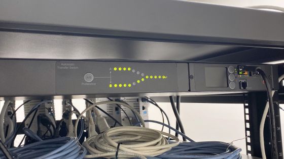
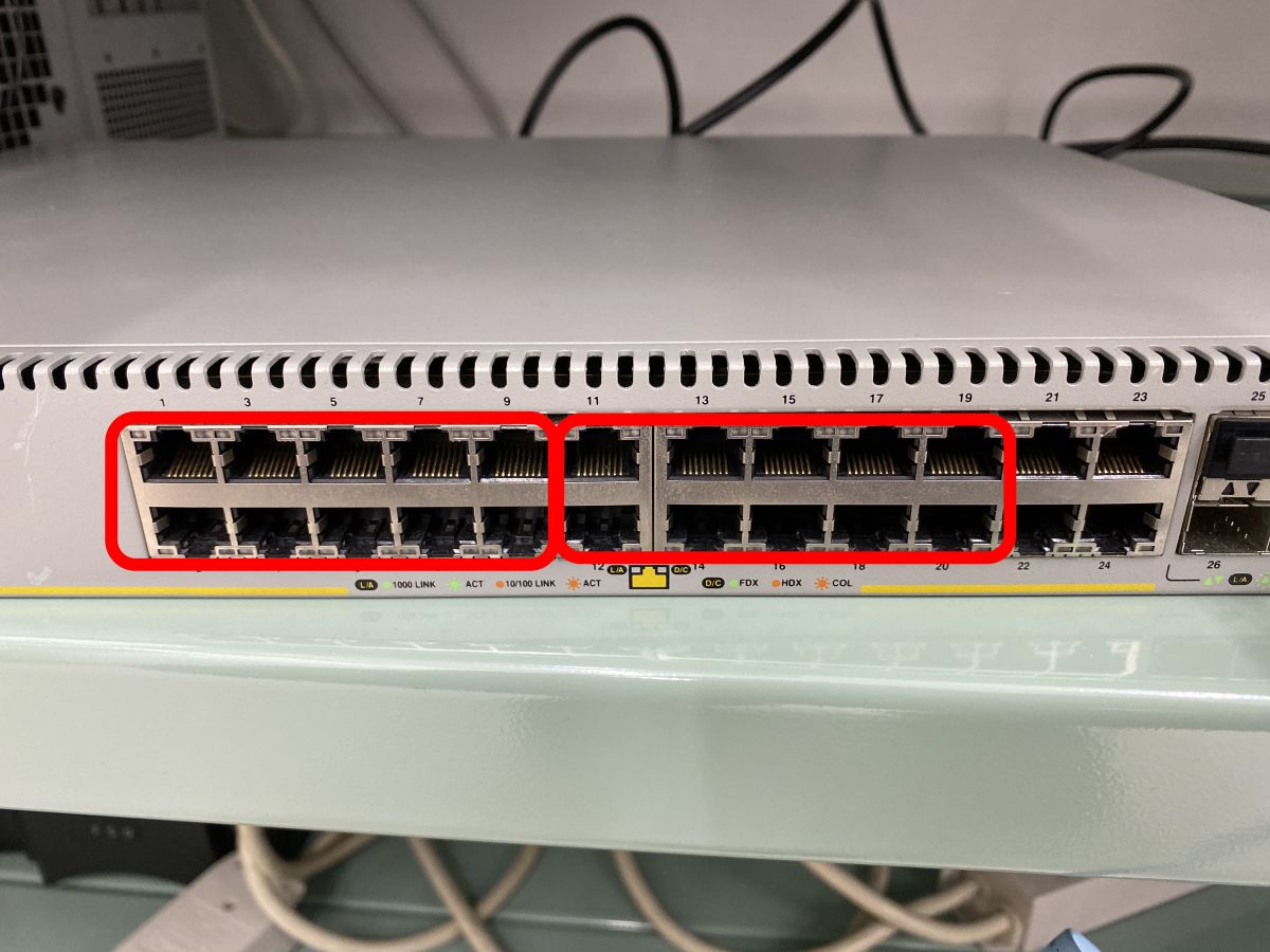
This is the actual switch. In addition to 28 LAN ports, there are 4 SFP + ports.
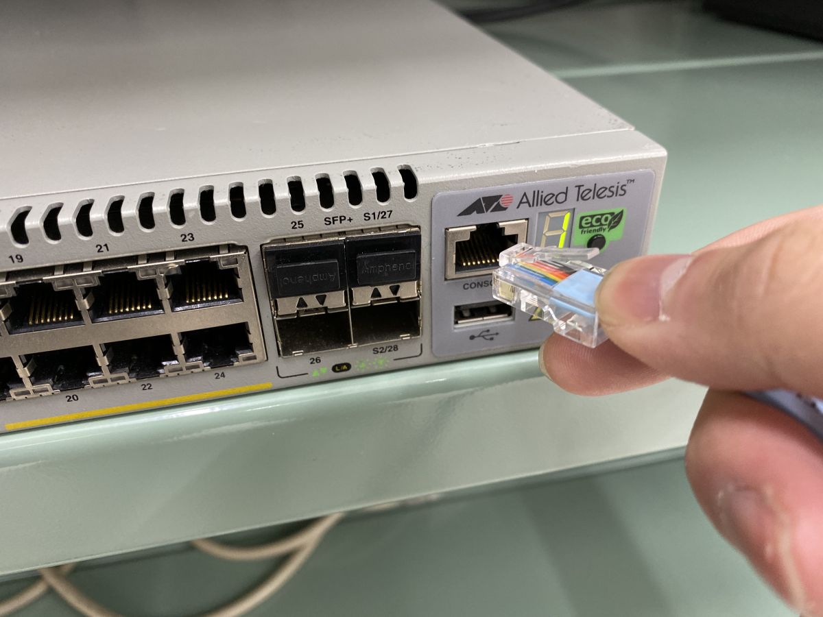
Connect to PC using console port.
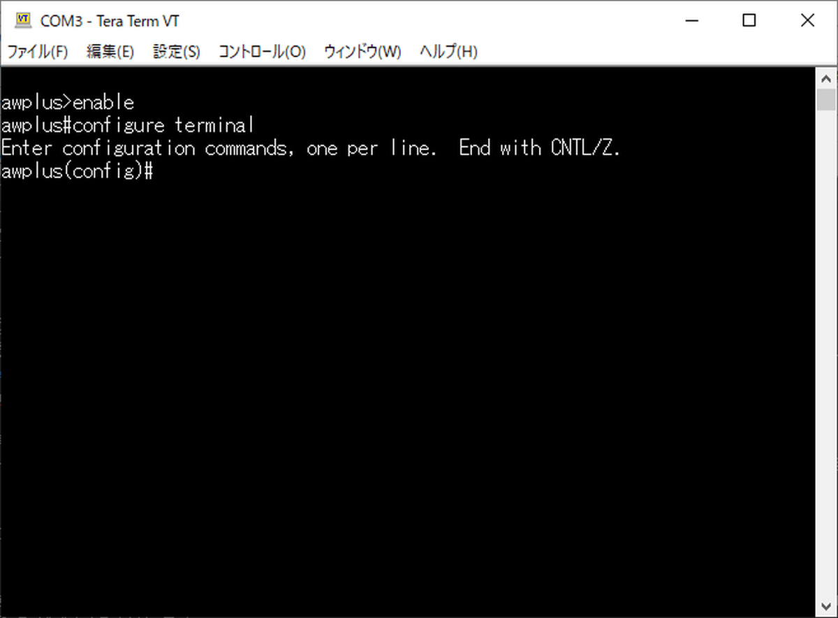
This time, the console screen was opened using the terminal emulator

Various settings of the x510 series switch are performed in a mode called global configuration mode. You can enter global configuration mode by typing 'configure terminal'.
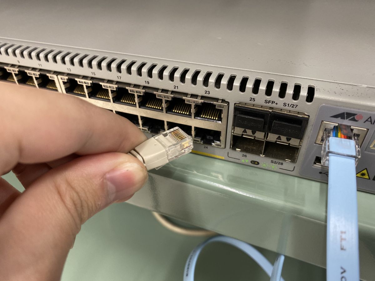
Execute the following command to assign a management IP address to the 24th port because you want to perform remote control via
[code]
awplus (config) # interface port1.0.24 ↓
awplus (config-if) # ip address 192.168.XXX.XXX/24
[/ code]
After assigning an IP address to port 24, connect port 24 to the LAN. You can now configure the switch via SSH.
This time, we wrap two
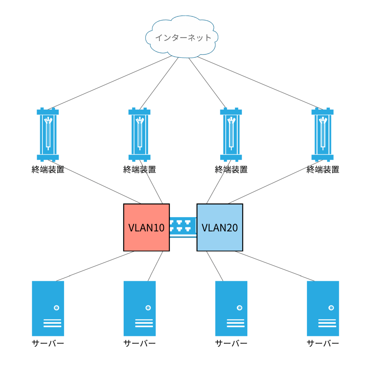
So set VLAN10 and VLAN20 on the switch.
[code]
awplus (config) # vlan database ↓
awplus (config-vlan) # vlan 10,20
[/ code]
Ports 1 to 10 are assigned to VLAN10, and ports 11 to 20 are assigned to VLAN20.
[code]
awplus (config) # interface port1.0.1-1.0.10 ↓
awplus (config-if) # switchport mode access ↓
awplus (config-if) # switchport access vlan 10 ↓
exit ↓
awplus (config) # interface port1.0.11-1.0.20 ↓
awplus (config-if) # switchport mode access ↓
awplus (config-if) # switchport access vlan 20
[/ code]
When the settings are saved, the switch settings are complete.
[code] write [/ code]
Connect two terminators and two servers to one VLAN. Two terminal devices and two servers are connected in the red frame.
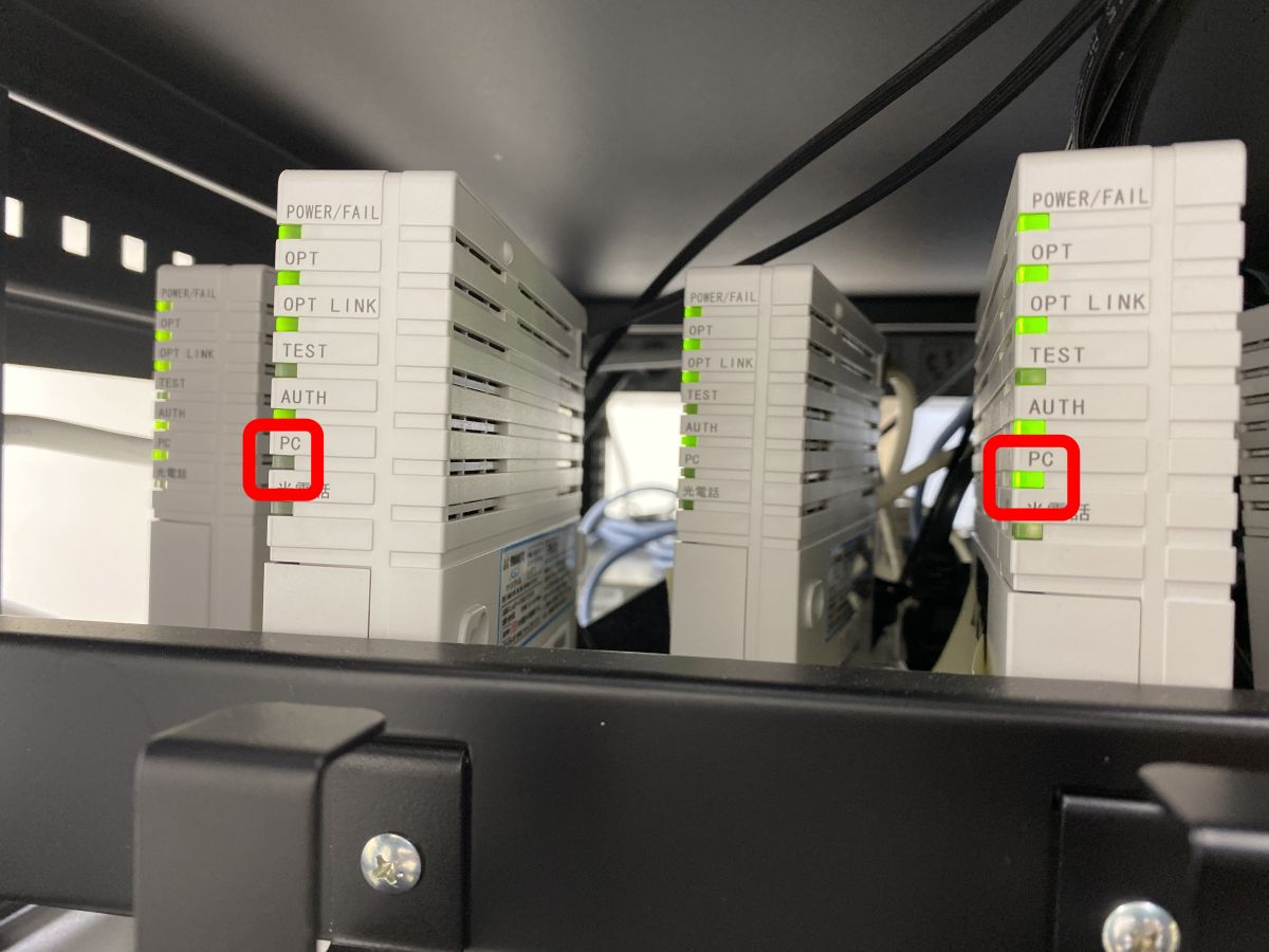
Hopefully, the 'PC' light will start flashing, indicating that the terminating device is being used to communicate with the Internet.
There are few cases where a server is directly connected to a terminating device without going through a router. However, if there are multiple optical lines, the terminating device can be made redundant using the VLAN function of the switch.
Related Posts: