How does "helicopter engine" fly a sky that has tons of weight to the sky?
ByAlexandre Prévot
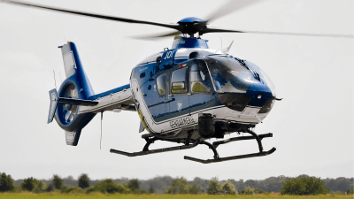
Helicopter can fly a few tons of aircraft weight only by rotating the propeller. A YouTube channel that explains complicated technologies easily with movies about how the engine "Turbo shaft engine" that turns such a propeller powerfully is structured "LearnEngineering Japanese"Explains it.
Understanding helicopter engines | Turbo shaft engine - YouTube
For many helicopters, "Turbo shaft engine" is used as an engine to rotate the propeller.
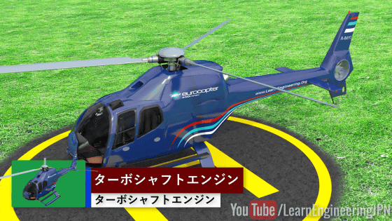
Try to remove the engine mounted under the propeller from the helicopter.
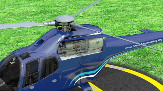
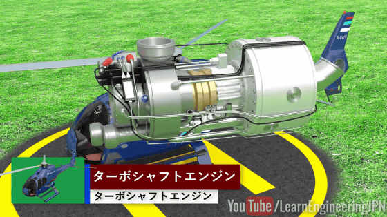
Turbo shaft engine is a single body like this. Turbo shaft engine is one type of "jet engine" which is light, compact and features high output. Among them, the feature of this helicopter jet engine is the place to convert the power of the engine into "rotating force".
There are multiple types of jet engines. For example, the "turbofan engine" used for jet airplanes and the like creates thrust by creating a strong air flow "jet" (jet) by turning the turbine with high temperature / high pressure combustion gas that burned fuel inside At the same time, turning a huge propeller "fan" in the turbine and creating a bigger air flow also creates a force to move forward by matching thrust.
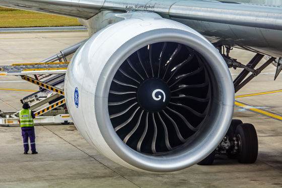
ByRattaphol Kerdkaen
On the other hand, the turbo shaft engine used for the jet helicopter rotates the turbine in the same way as the jet engine, but it creates the force "lifting force" by transmitting almost all of its power to the rotor. At this time, the jet flow produced by the jet engine rarely is used as a power to fly, it is a big difference from the turbofan engine.

ByAlexandre Prévot
Next, let's look at the inside of the engine.

Inside the "turbine" with metallic feathers are overlapping in many stages, each turbine has its own role.

When further parts were removed, "Power shaft" penetrating the center of the engine and "Power turbine" behind appeared. This is the core part of the turboshaft engine.

High temperature / high pressure exhaust gas is produced by the engine, and it is rotated in the way of the wind turbine receiving the feather "blade" of the power turbine. Next, the rotation of the blade is transmitted to the power shaft.

The blades of the power turbine receiving the exhaust of the engine have the same cross-section structure as the blades of the airplane. High temperature and high pressure combustion gas strikes this blade, thereby efficiently rotating the power turbine.

In addition, at the tip of the blade, "stator blade" is fixed inside. This stationary blade stabilizes the exhaust flow and makes blade rotation more efficient.

Next, let's see the part that burns fuel and produces force. The "power shaft" and "power turbine" that we have been looking at so far are shown in light blue color, the part indicated by orange "gas producer turbine" is the part that generates force inside the engine.

The light blue part and the orange part are arranged coaxially, but each has an independent structure. As a result, each turbine rotates in the opposite direction as shown in the following figure. This is a device to cancel the 'gyro effect' inside the engine that rotates at high speed and stabilize the flight.

The shaft power is transmitted forward through the power shaft on the left side of the image.

The shaft power is transmitted to the rotor and rotated.

And the helicopter can fly by rotation of the rotor or propeller.

ByRoman Kopacek
Next, let's see "Where will it be produced?" "High temperature / high pressure exhaust" produced by the engine. First of all, air is taken in from the outside of the airframe on the left side of the image, it is compressed by the compressor and divided into the back of the engine and sent.

The compressor is a hollow shaft.

In addition, the compressor is connected to "gas producer turbine". The compressor is getting energy to compress by the rotation of the gas producer turbine.

The air compressed by the turbine goes to the "combustion chamber" on both sides of the power turbine.

Inside the combustion chamber, the medium temperature / high pressure air sent from the previous stage is folded back and is flowing forward. By injecting particulate fuel, mixing and burning it, high pressure and high temperature exhaust are born.

Then, the exhaust reaches the power turbine, the shaft output is produced and the rotor rotates.

Such a "centrifugal compressor" is installed in the last part of the compressor compressing the air.

By using a centrifugal compressor, I change the direction while compressing the air sent from the front and send air to the rear combustion chamber.

Turbo shaft engine, other advanced technology is used.

One of them is the structure of the combustion chamber "backflow type combustion chamber".

The compressed air entering from the front of the engine is sent to the combustion chamber.

However, the air does not go directly to the combustion chamber but flows so as to bypass the combustion chamber.

And there is a hole around the combustion chamber. Compressed air from there is injected to surround the hot exhaust air.

In this way, injecting medium temperature air into the combustion chamber is to protect the engine from high temperature combustion gases of 1700 degrees Celsius.

Metallic materials used in engines can not withstand this high temperature. In order to solve this problem, a small hole "hole" inside the combustion chamber and a gap "slot" are made, and by injecting compressed low temperature air, a protective layer is made to protect the engine from high temperature. For this purpose, about 80% of the air flowing into the engine is used for cooling purposes. Also, by adopting a backflow type combustion chamber, the merit of shortening the total length of the engine is also born.

Some techniques are used when abnormalities occur. One of them is "control at the time of compressor stall".

Once the compressor stall occurs, the shaft output of the engine will be zero, creating a crisis situation. This phenomenon occurs when the flow of air striking the blade of the compressor separates from the face of the blade.

The big cause is the case of "bird direct hit", "air speed decrease" or "friction or crack". However, in the case where the flow of air has just separated, this trouble can be avoided by controlling the variable pitch fixed wing inside the engine.

Explaining the compressor stall in detail, a new movie is necessary. So in Learn Engineering Japanese that movie will be coming soon.

Related Posts:
