GPS antenna modification method to make Starlink antenna less susceptible to interference waves and enhance reception sensitivity
The antenna of Elon Musk's satellite communication service ``Starlink'' may not be able to capture useful signals, and reception may be interfered with by other signals. Software engineer Oleg Kutkov explained how to modify the antenna to improve this.
Connecting external GPS antenna to the Starlink terminal – Oleg Kutkov personal blog
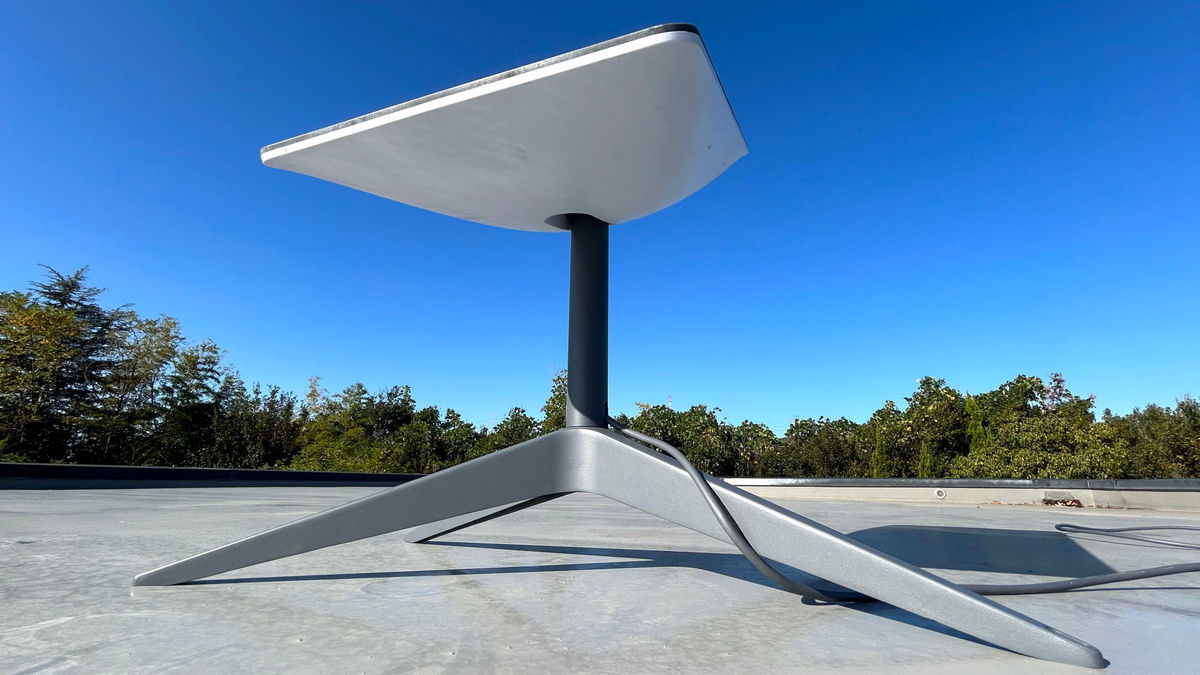
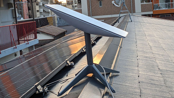
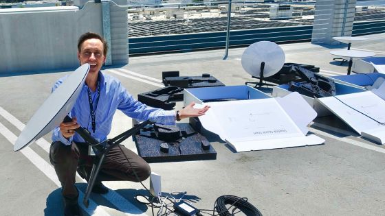
There are several types of Starlink antennas, and they are called 'REV1' and 'REV2' in order from the first generation. REV1 and REV2 are round, the square antenna below reviewed on GIGAZINE is REV3, and the model released in November 2023 is REV4. There are other variants such as 'High Performance'.
I set up the satellite-based internet ``Starlink'' that I bought at Costco and tried connecting to the internet.Review - GIGAZINE
All Starlink antennas use ST's Teseo series of automotive receivers for GPS signal acquisition. This is a receiver that can acquire multiple location information data such as GPS/Galileo/GLONASS/BeiDou/QZSS, and Kutkov says it is 'highly reliable and full of features.' However, it is also susceptible to interference. In REV1, flash memory and SoC 'STA8090' were used, but after that the flash memory was removed and the chip was switched to the cheaper 'STA8089'.
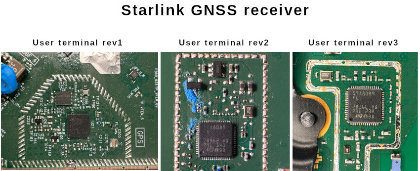
The internal structure of the antenna is also different; the round REV1 and REV2 have more space and use a quarter-wavelength patch antenna, but the REV3 uses a compact ceramic chip antenna. This difference makes it easier for REV1 and REV2 to pick up GPS signals under some adverse conditions.
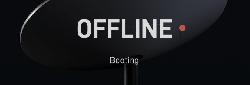
The REV3 chip antenna is a low gain (~3dB) omnidirectional antenna. In general, low-gain antennas have weaker communication strength than high-gain antennas, so they have better directivity, but the low-gain antenna installed on Starlink tries to capture all radio waves from satellites in the sky and nearby radio waves. , positioning may fail and enter the 'boot' state. In the worst case, it may remain in the boot state forever or damage the chip.
It seems that these problems can be solved by modifying the device to separately attach a suitable GPS antenna.
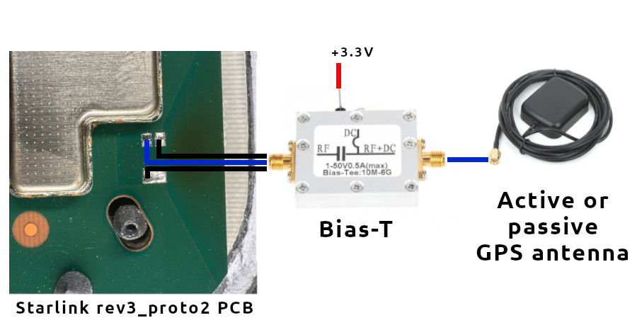
Both passive and active antennas can be installed on the Starlink antenna. Circularly polarized directional antennas make it easier to capture the circular polarization of GNSS signals, providing protection from jamming signals and faster positioning.
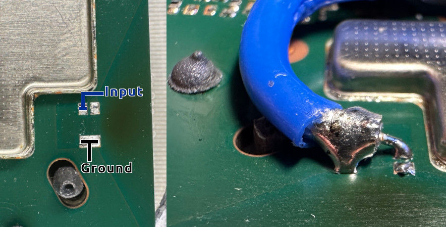
External antenna cables can also be connected directly to the Starlink PCB instead of the chip antenna. First remove the chip antenna, then solder the coaxial cable directly to the PCB. It seems to be convenient to attach the cable shield to the Ground pin.
For power supply, you can connect directly to an external antenna or use a bias tee.
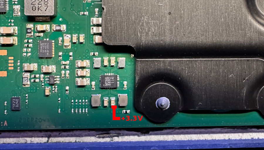
There is a voltage regulator on the PCB, you can get 3.3V power.
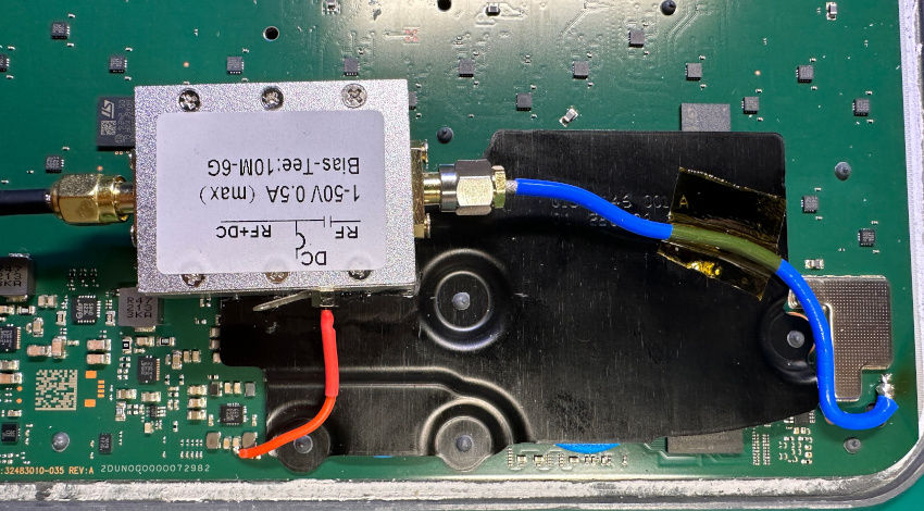
This is what it looks like when connected from the PCB to the bias T.
Kutkov is conducting tests with three GPS antennas.
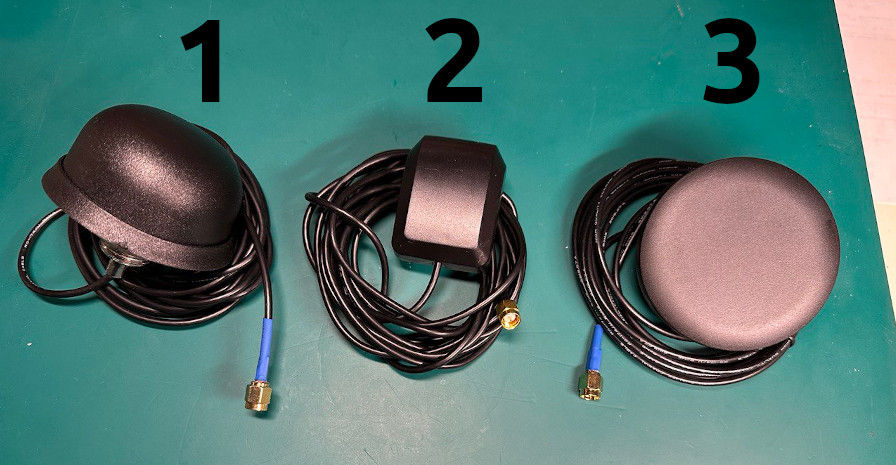
The results are below. Both antennas have lower uptime than standard chip antennas.
| antenna | Time to GPS Fix | Number of satellites captured | GPS enabled |
| built-in chip | 3 minutes | Five | yes |
| 1 | 30 seconds | Ten | yes |
| 2 | 30 seconds | Ten | yes |
| 3 | 45 seconds | 13 | yes |
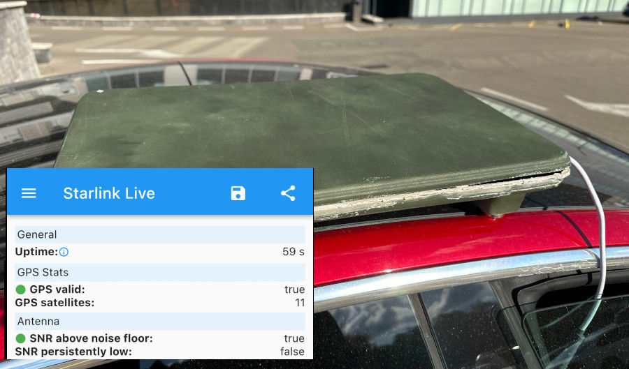
As I know from my review, Starlink takes a very long time to search for satellites when it starts up. As a result of the adjustment, Mr. Kutkov succeeded in capturing 11 satellites within one minute.
Related Posts:

in Hardware, Posted by log1p_kr