A fierce man who remodeled 'Cartridge that allows Game Boy to connect to Wi-Fi' appears

Engineer
There oughta be a WiFi Game Boy cartridge.
https://there.oughta.be/a/wifi-game-boy-cartridge
At the time of writing the article, the Game Boy cartridge with Wi-Fi function created by Mr. Starks is very limited in that it can only demonstrate communication using Telnet and access Wikipedia.
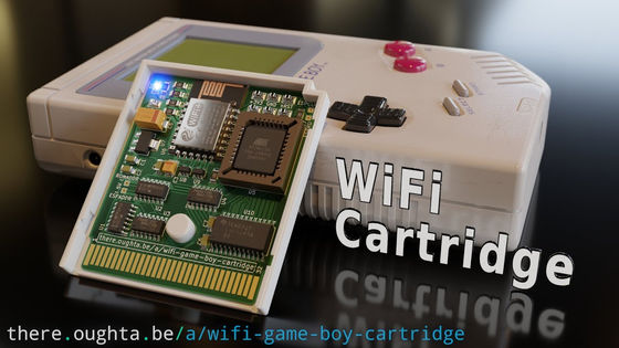
The Game Boy Cartridge with Wi-Fi function is a Game Boy cartridge equipped with an ESP8266 microcontroller for adding Wi-Fi function. The ESP8266 microcontroller has a lot of pre-processing for the Game Boy and is only available on Wikipedia at the time of writing, but 'it's possible to implement a Twitter client or Reddit browser,' Starks said.
The following is how to access Wikipedia using a Game Boy cartridge with Wi-Fi function. The image on the left is a simple screen where the IP address etc. are displayed when the Wikipedia demo app is started. In the middle, you are searching for a specific page on Wikipedia using the on-screen keyboard, and on the right, you can see the beginning of the article.

Of course, you can't play games online or access the ROM library over the network with this cartridge. With this cartridge, the software
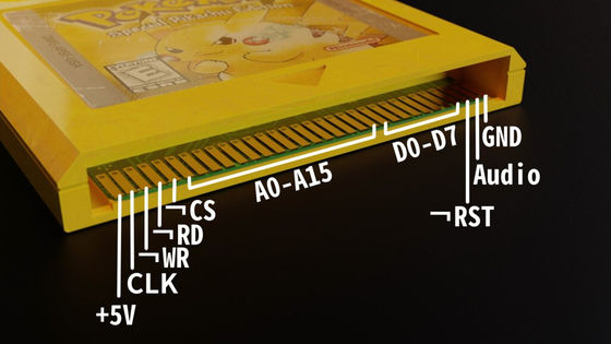
In the first place, the Game Boy cartridge has 16 address pins and 8 data pins. In Game Boy, set the memory address to read and write with the address pin, and read and write 1 byte of data with the data pin. These accesses are controlled by clock pins (CLK), read pins (RD), write pins (WR), and chip select pins (CS). RD and WR are used to declare whether to read or write data, while CLK is used to send and receive a 1MHz reference clock signal for read / write timing. CLK plays a role in preventing RD or WR from returning to the off state during continuous reading and writing. Therefore, it is very difficult to identify the read / write sequence without CLK.

CS is a pin that has little to do with the cartridge and is usually used to enable or disable a particular chip to switch between different chips on the same bus. The 16 address pins of the Game Boy cartridge
With the latest microcontrollers, you can connect to all these pins and communicate with software. However, you may need a level shifter or bus transceiver, and the problem is that a large number of pins limits the appropriate microcontroller. However, even in other cases, 'the latest 100MHz microprocessor was able to communicate with the Game Boy CPU (operating frequency 4MHz) that exchanges on the 1MHz data bus without problems,' Starks wrote. .. In fact, we have confirmed that two non-genuine Game Boy cartridges , 'STM32 ' and ' RP2040', were able to communicate without problems.

The problem is that the cartridge has a memory cycle of only 1MHz. This means that there is only one byte read / write per cycle. This may seem more versatile than a CPU cycle, but it's the task of the CPU checking the address pins, interpreting their meaning, and getting or calculating the responsive data and outputting it. Cannot be completed in one cycle. However, the Game Boy CPU can handle interrupts without actually doing anything. In the case of Game Boy, the time for interrupt processing is only
Even though interrupt processing is occurring, some preliminary processing time is required. In this case, you need to connect to Wi-Fi with Game Boy to access Wikipedia. However, the data processed on the Game Boy is only the data output, and since the JSON response of Wikipedia is programmed to be processed on the ESP8266 microcontroller, it is possible to process the data without problems only by interrupt processing. It seems that it was.
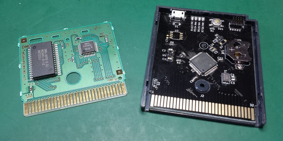
Also, to reduce the number of memory requests that the microcontroller has to handle and the number of pins that the microcontroller has to manage, Starks does not replace the entire cartridge with a microprocessor, but rather routinely. He decided to use it as an EEPROM for the 32kiB component, which is ideal for handling memory requests. The reason is explained by Starks, 'Most memory requests are static, such as images and bytecodes running on Game Boy, so the frequency of retrieving data from ESP is inevitably low.' ..
In addition, map 2 bytes (0x7ffe and 0x7fff) of Game Boy memory space to ESP8266 to get data from ESP. Access 0x7ffe when reading ESP from the Game Boy side, and access 0x7fff when writing. These are at the end of the normal 32kiB ROM space, because they only interfere with the program code when using the entire 32kiB and are very easily recognizable by some logic gates.
The circuit diagram of the Game Boy cartridge with Wi-Fi function created by Mr. Starks is as follows.

Mr. Starks continued to work on software development. He said, 'There are two pieces of software that need to be created:' the code stored in the EEPROM to run on the Game Boy 'and' the software that runs on the ESP8266. ' 'Code stored in EEPROM for execution by Game Boy' is written using gbdk-2020, a freeware for developing programs for Game Boy. The hard part is 'software running on ESP8266', and Starks says he programmed the software using the Arduino IDE.
The two software used in Game Boy cartridges with Wi-Fi is both hosted on the GitHub page below.
GitHub --Staacks / wifi-game-boy-cartridge: A WiFi cartridge for the original Game Boy.
https://github.com/Staacks/wifi-game-boy-cartridge

You can check how the Game Boy cartridge with Wi-Fi function created by Mr. Starks is actually working in the following movie.
WiFi Game Boy Cartridge-YouTube
Related Posts:


