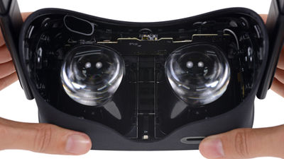
Disassemble VR headset "HTC Vive" apart
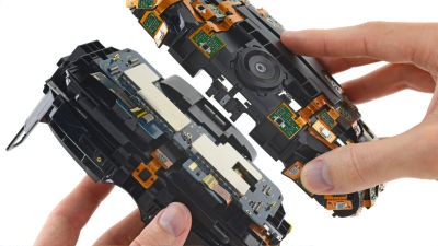
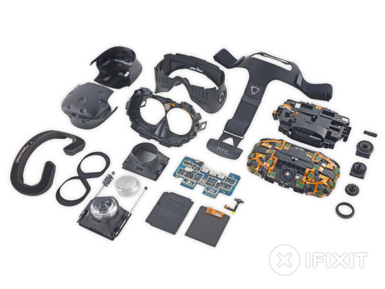
"Repairing the user's rightWith the policy saying, we disassemble every gadget and publish a repair guideIFixit, VR headset "HTC Vive"Is being disassembled.Oculus RiftThe full-fledged VR headset Vive which was disassembled following, there is a part which is different from the same part as Rift, it seems that a difference in design philosophy appears.
HTC Vive Teardown - iFixit
https://www.ifixit.com/Teardown/HTC+Vive+Teardown/62213
The appearance of decomposing HTC Vive can be confirmed in the following movie.
HTC Vive Teardown Review! - YouTube
HTC Vive finally arrived at iFixit. Like Oculus Rift,It is difficult to obtain from immediately after releaseIt is in
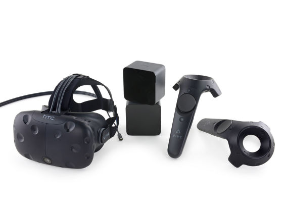
This is HTC's VR headset "Vive". The display with 1080 × 1200 pixels for one eye and 2160 × 1200 for both eyes is mounted, the refresh rate is 90 Hz and the horizontal viewing angle is 110 °.
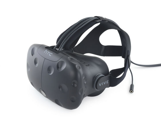
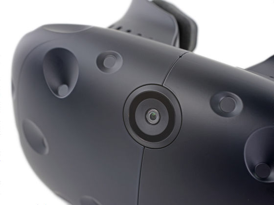
Vive's big feature is to mount a camera on the front.
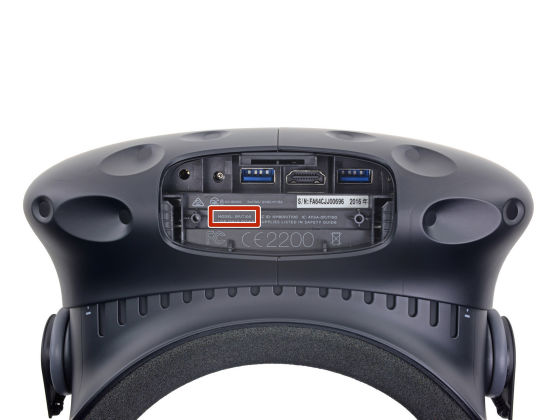
When using, connect 4 cables.
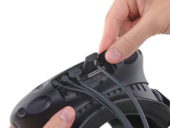
External terminal is 3.5 mm audio jack, USB 3.0 × 2, HDMI terminal.
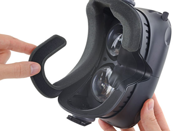
Start decomposing at once. First remove the sponge inner.
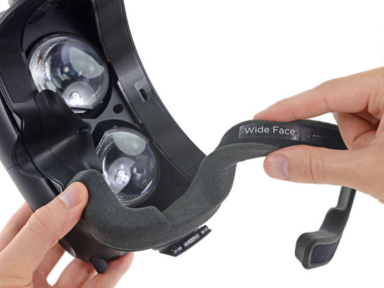
In addition, the sponge is fixed with Velcro, it is interchangeable.
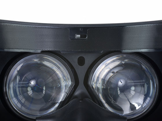
Between the lenses is a proximity sensor.
Remove the focus adjustment screw.
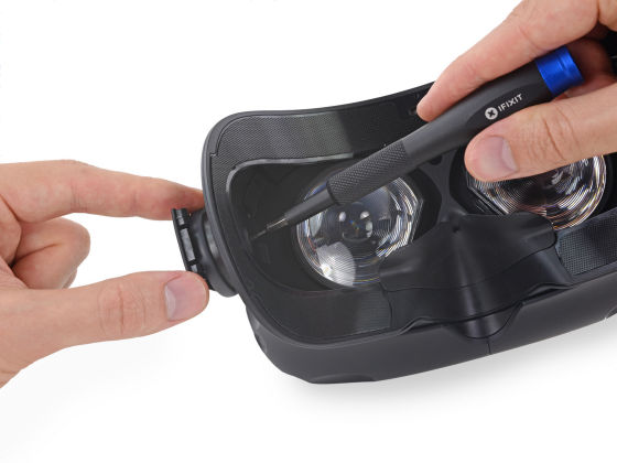
Like this.
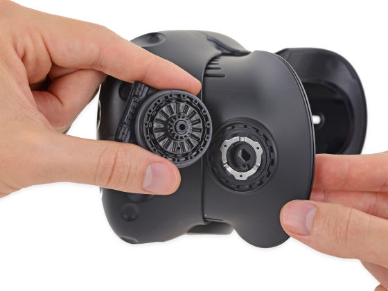
Remove the plastic part of the mask part ... ...
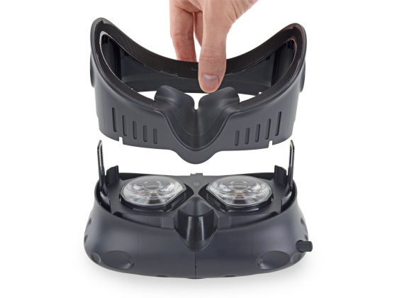
The front cover is also disassembled in left and right direction.
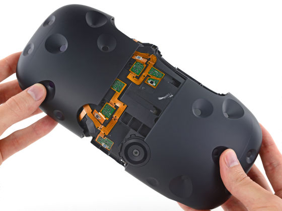
Removing the cover, the modules such as photodiodes and IR lasers are rigid. The number of sensors is 32 pieces. Oculus' s Rift is motion tracking with a desktop camera, but Vive is a mechanism to detect light and track motion with the IR sensor in the headset.
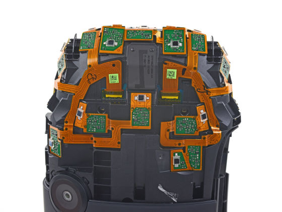
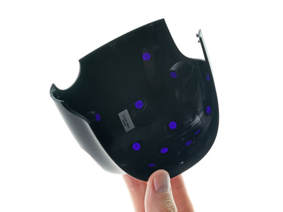
In addition, many IR filters are installed in the cover so that light can be correctly transmitted to the photodiode.
The module is mounted with a ZIF connector.
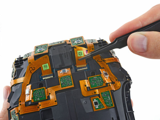
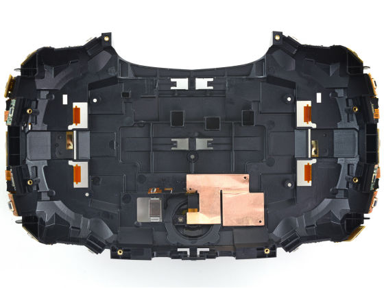
Remove the connector under the front camera and lift the sensor array to disassemble it back and forth.
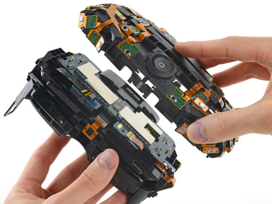
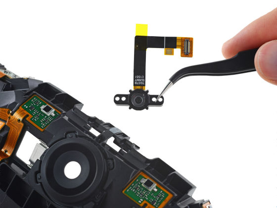
The back side of the front part with the camera looks like this.
The cameraSunny Optical Technology"TG 07 B C 1551" made by ToshibaOnePlus OneYaProject TangoIt is the same camera module as the terminal.
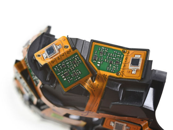
The sensor is numbered "18" and "19" individually.
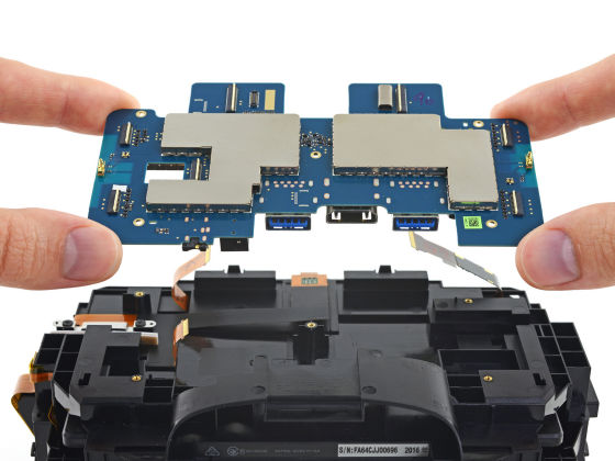
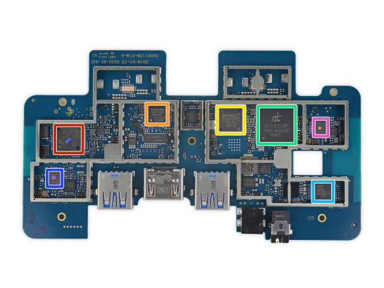
Vive's motherboard looks like this. An electromagnetic shield is attached.
The red frame is "STMicroelectronics"STM32F072R8", The CPU uses ARM's"Cortex-M 0"Is used. Orange frame is Toshiba 's HDMI - MIPI converter "TC 358870 XBG", The green frame is the SoC of Alpha Imaging Technology"AIT 8328", The blue frame is the flash memory of Micron"M25P40(PDF file) ", purple frame is flash memory of Micron"N25Q032A13ESE40E".
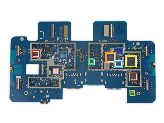
On the back side, the red frame is Nordic Semiconductor's SoCNRF 24 LU 1 +(PDF file) ", Orange frame is" NXP Semiconductors "LPC 11 U 3 x, Green frame is Invensense's gyroscope · acceleration sensor "MPU-6500".
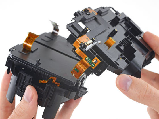
Separate the frame that fixed the motherboard.
Also remove the lens cover of the intermediate frame.
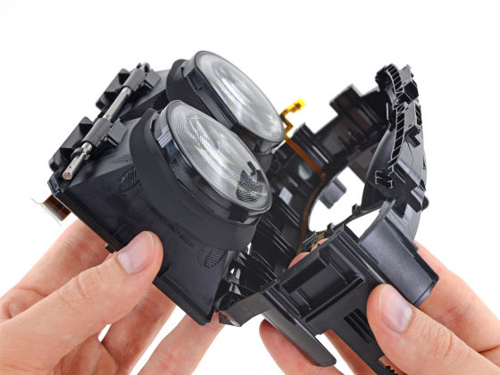
Removing the rubber gasket around the lens ... ....
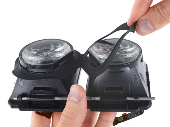
Arrived at the lens.
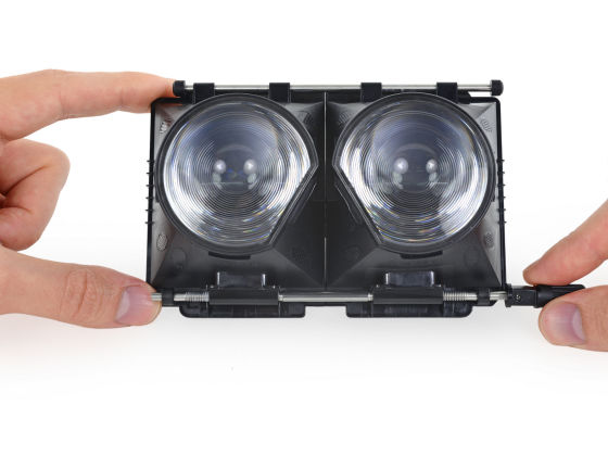
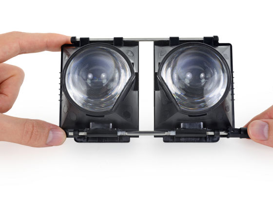
Rotate the knob on the bottom right of the image to change the lens spacing.
Next, remove the display part attached under the lens.
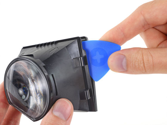
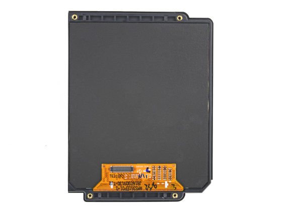
The display is an organic EL panel.
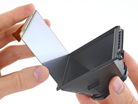
The pixel density is 447 ppi, the diagonal size is 91.8 mm (3.6 inches). By the way, Rift is 456 ppi and the diagonal is 90 mm.
The lens is fixed with adhesive.
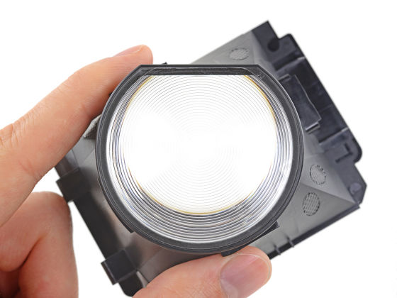
Since the amount of adhesive is small, it is relatively easy to remove.
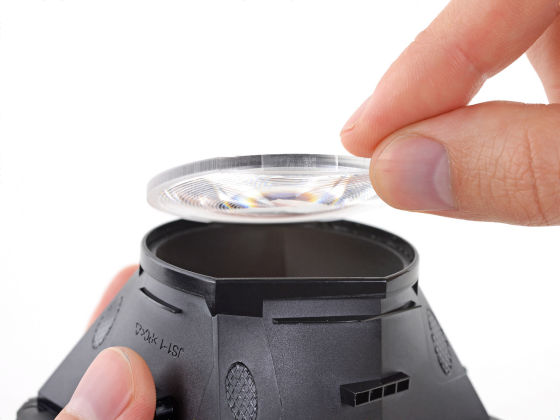
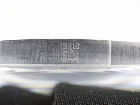
Although there is a QR code on the side of the lens, it was not possible to scan anyway, so the details are unknown.
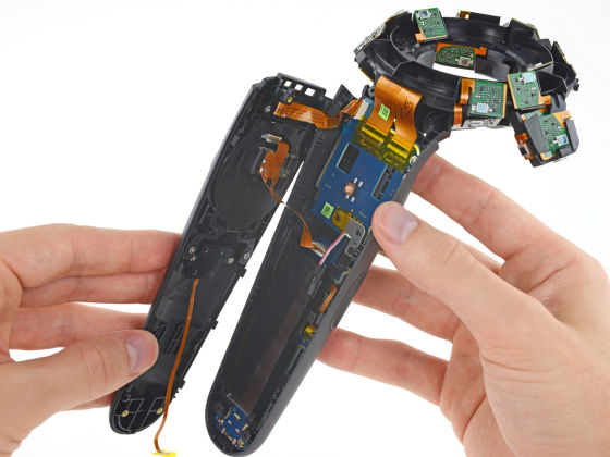
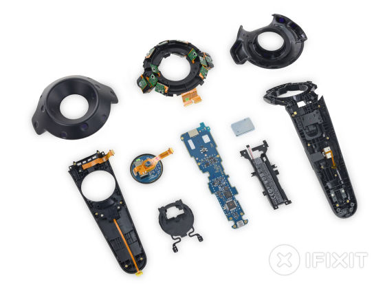
Continue to disassemble controller.
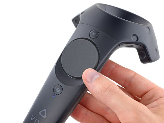
First, remove the tip cover.
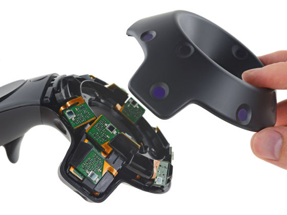
It is said that booby trap is installed in the cover on the front side. Care must be taken at the angle of opening the case so as not to cut the cable.
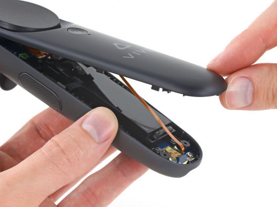
It is like this when removed well.
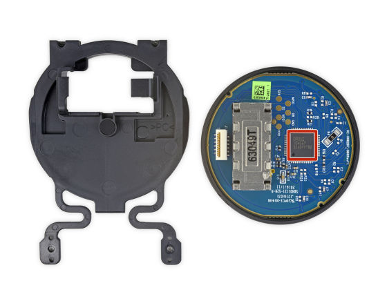
On the touchpad part, "1CA027" chip of Cirque is mounted as a red frame.
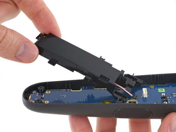
Removing the battery.
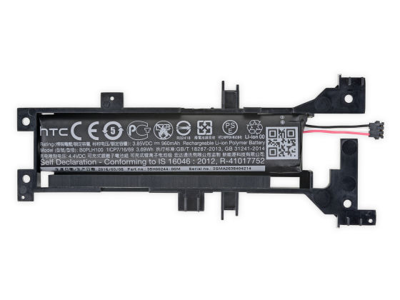
The model number of the lithium polymer battery with the capacity of 960 mAh is "B 0 PLH 100". QR code is for serial number.
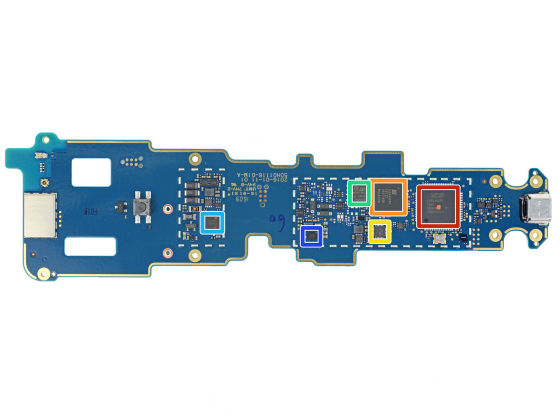
The controller's motherboard looks like this. Red frame is NXP Semiconductors'LPC 11 U 3 x(PDF file) ", yellow frame is" MPU-6500 "of Invensense, green frame is" M25P 40 "of Micron.
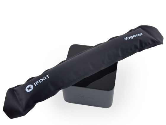
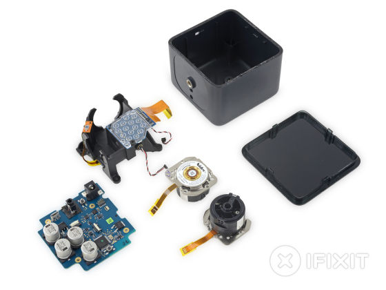
The base station for motion capture warms the top surface ... ...
Remove the cover.
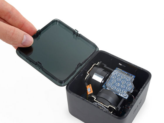
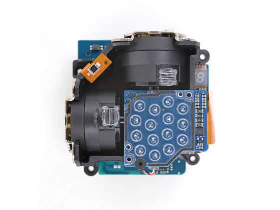
This is a device inside.
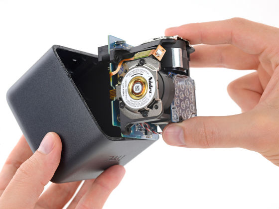
Laser emitter with spinning motor equipped with infrared LED.
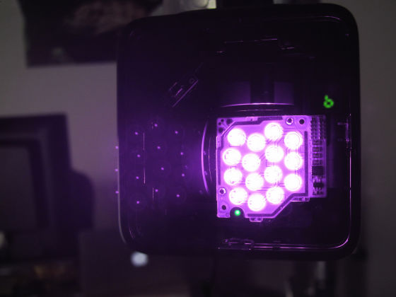
It is like this when shooting with an infrared camera.
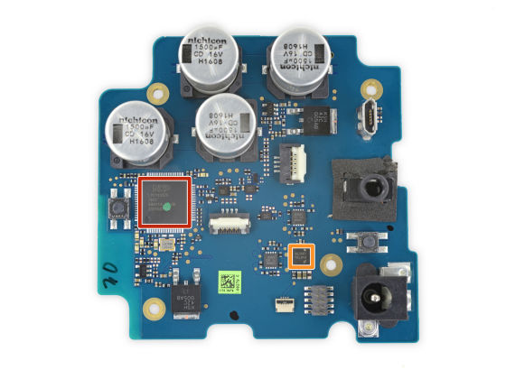
For the chip, the red frame is "11 U 37 F" of NXP Semiconductors and the orange frame is "61 AFCXU L00075 B" of National Semiconductor.
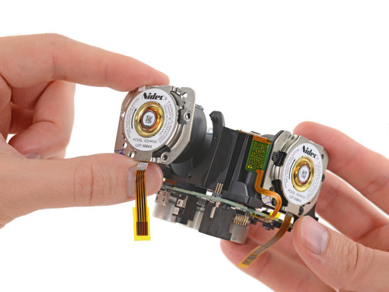
Nidec's "B2044N01" was used as a spinning motor.
So when you disassemble the Vive body apart like this.
controller
Base station
According to iFixit, the disassembly and repair difficulty of the HTC Vive kit is comparatively easy to say "10" in 10 steps.

The reason for this is that disassembly is easy because special screws are not used, that the touch pad of the controller and the motor of the base station etc are using general-purpose parts and the availability of exchange parts is good, it is used for part It is said that the adhesive is relatively easy to peel off.
Related Posts:

