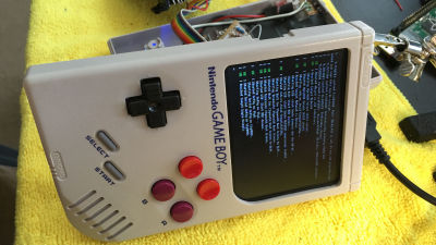
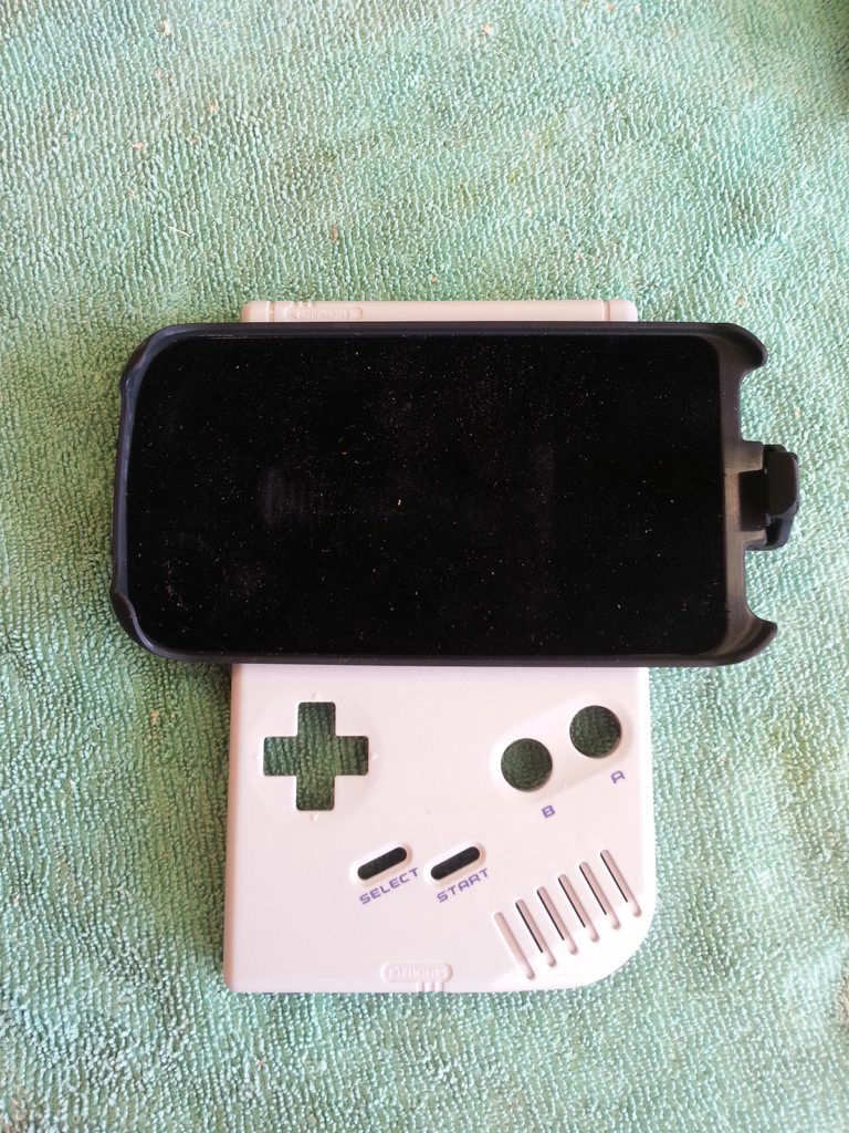
If you make a Game Boy a smartphone's physical pad with Wii remote control parts
Tomatoskins, who likes to use physical game pads when playing games on smartphones,Physical pad made by DIY by othersI mimicked making and using it. However, I wanted to improve my personal preference more, "Game Boy Bluetooth Game Pad"Has been created and the process is made public.
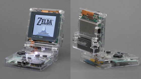
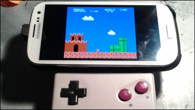
Game Boy Bluetooth Game Pad
http://www.instructables.com/id/Game-Boy-Game-Pad-For-Phone/
◆ 1: Material
The following six items are necessary to create "Game Boy Bluetooth Game Pad".
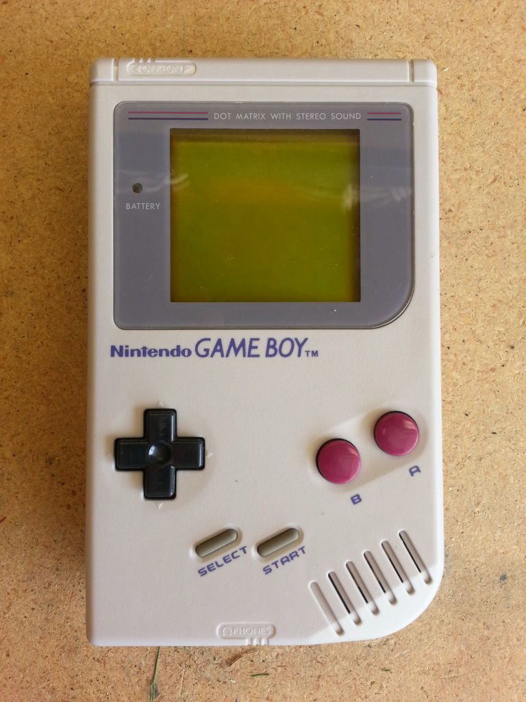
GAMEBOY (It does not matter if it is broken)
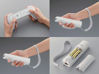
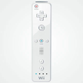
Working Wii Remote
Smartphone holder
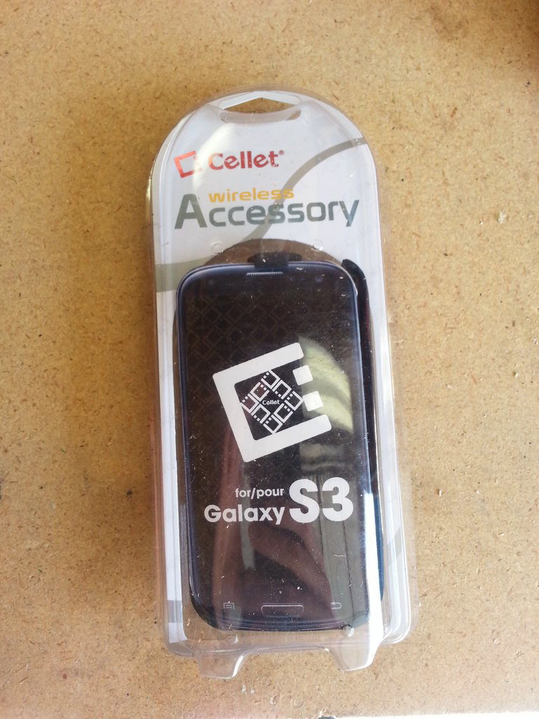
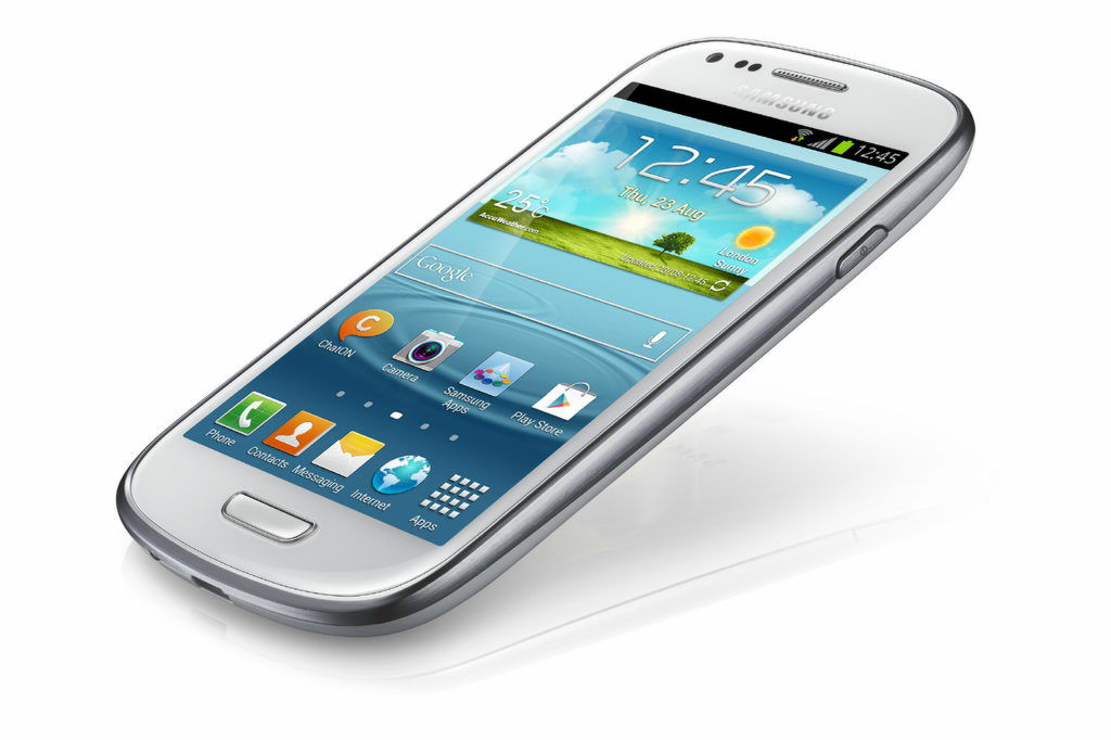
Wiimote ControllerSmartphones that can be used (tomatoskins uses GALAXY S3)
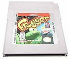
One cartridge of GAMEBOY
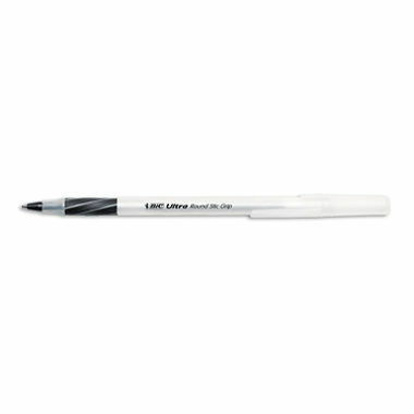
BIC'sRound Stic GripA pen cap called
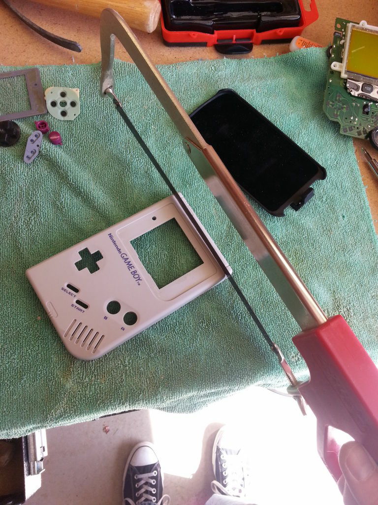
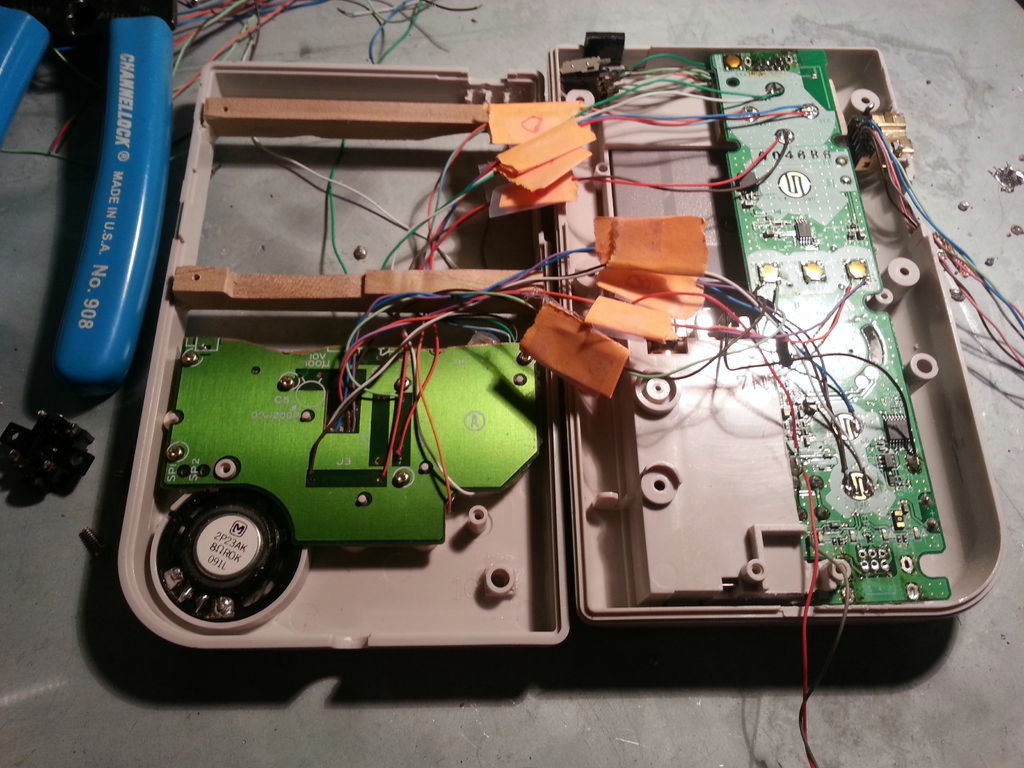
◆ 2: Disassembly
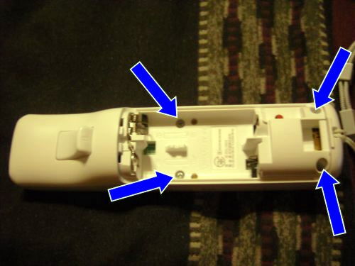
First we start with the demolition of "GAMEBOY" "smartphone holder" "Wii remote control".
The first thing to dismantle is a smartphone holder. If clips etc. are attached behind this, remove the clip part.
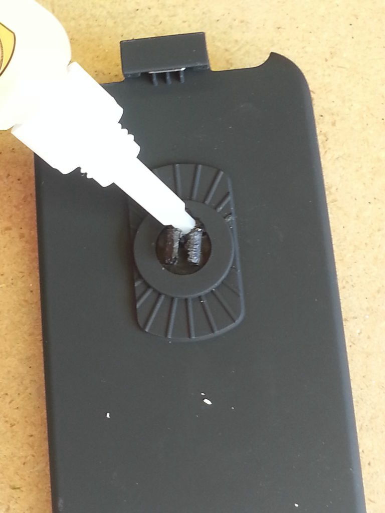
If there is a moving part fixed with bond etc.
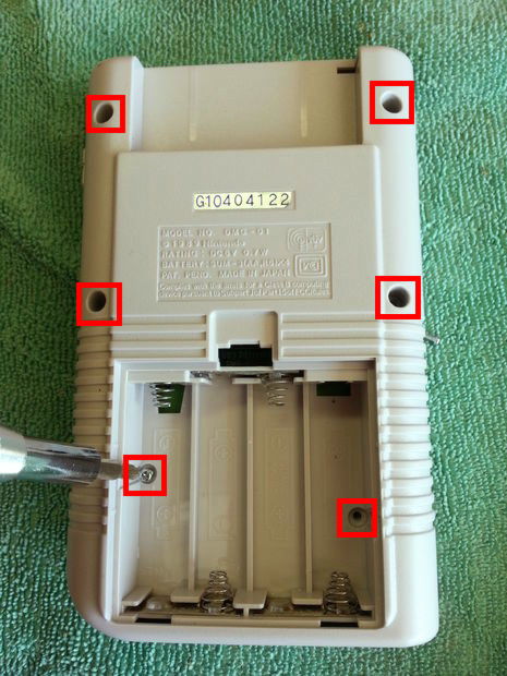
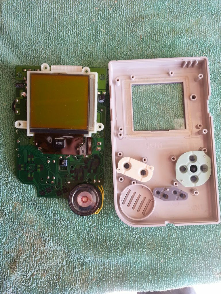
Next, demolition of GAMEBOY. Remove the six screws in the red frame part.
Capri.
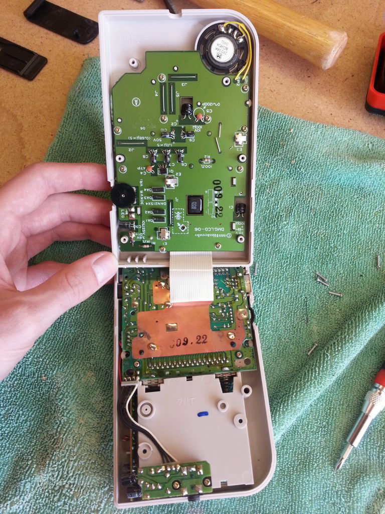
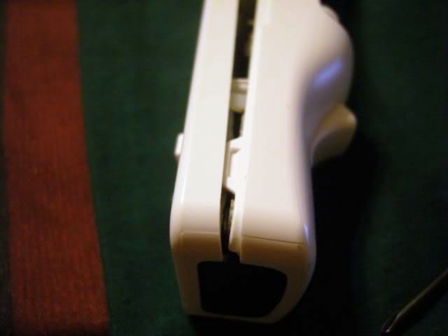
Since the ribbon cable connects the two main boards, slide it out from the board located on the back of GAMEBOY.
When it goes off, it feels like this.
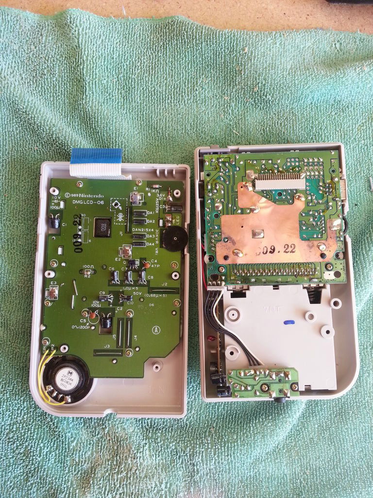
Remove the board from the back.
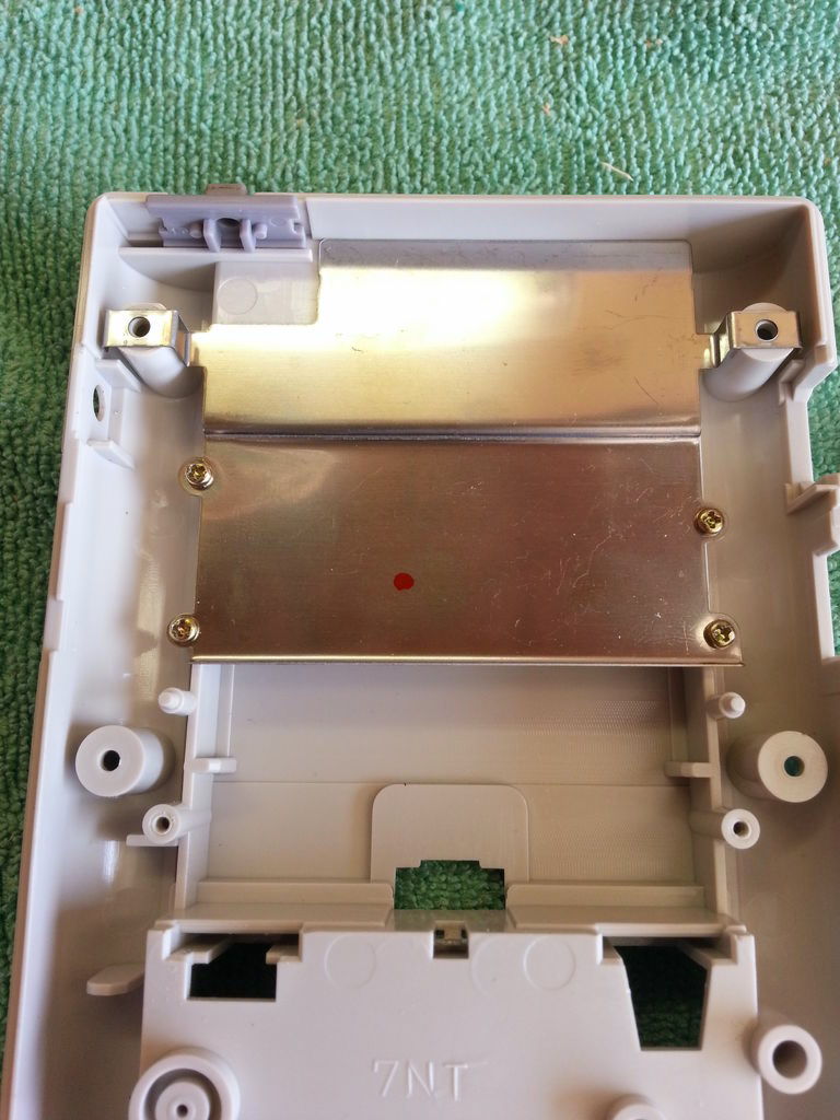
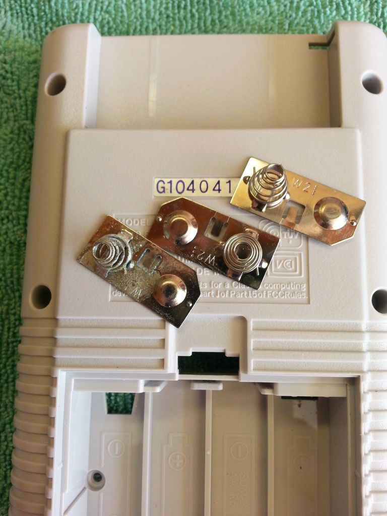
Remove the metal plate attached to the top body of the back ... ...
Push the part surrounded by the red frame of GAMEBOY's battery box.
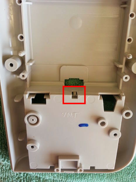
Then you can remove the contact fittings of the battery. Let's wash this bracket thoroughly.
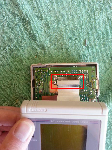
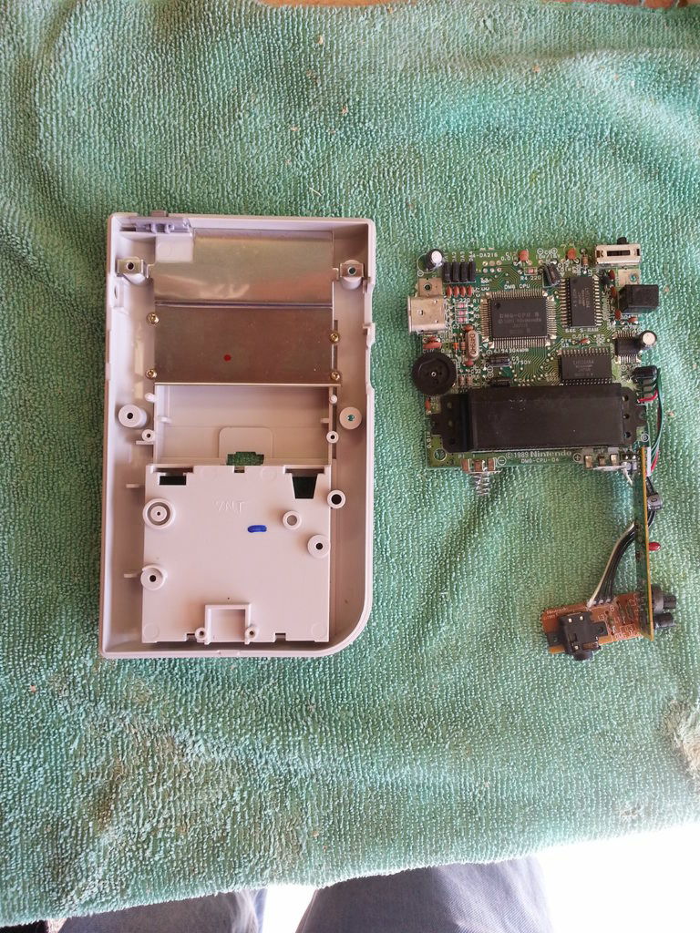
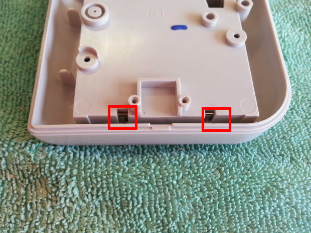
Also remove the base of the main display side.
Pull out the screws and remove the board ...
Remove the buttons and the cross key parts.
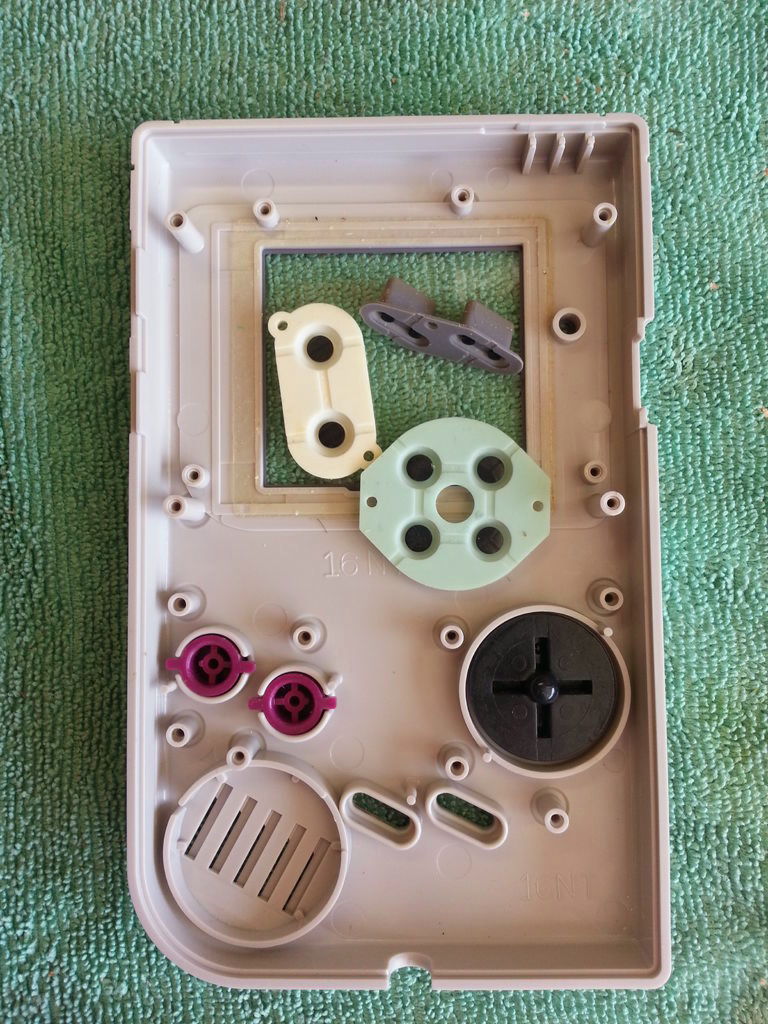
Removing the parts on the screen edge of GAMEBOY ......
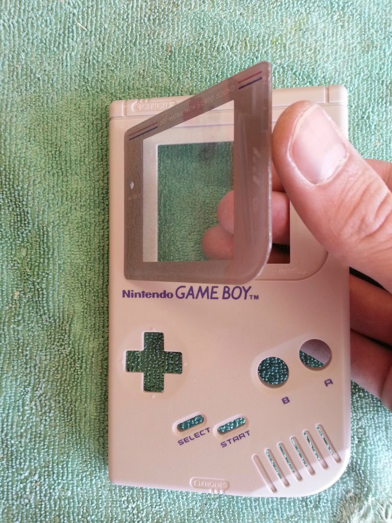
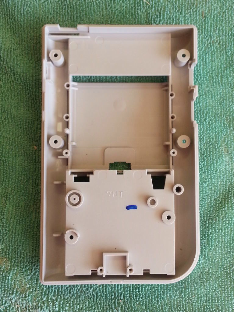
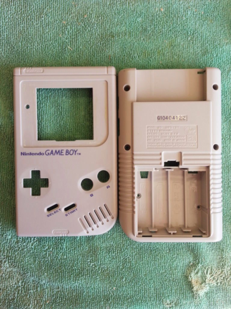
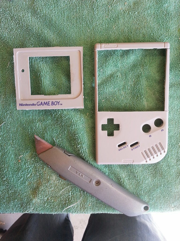
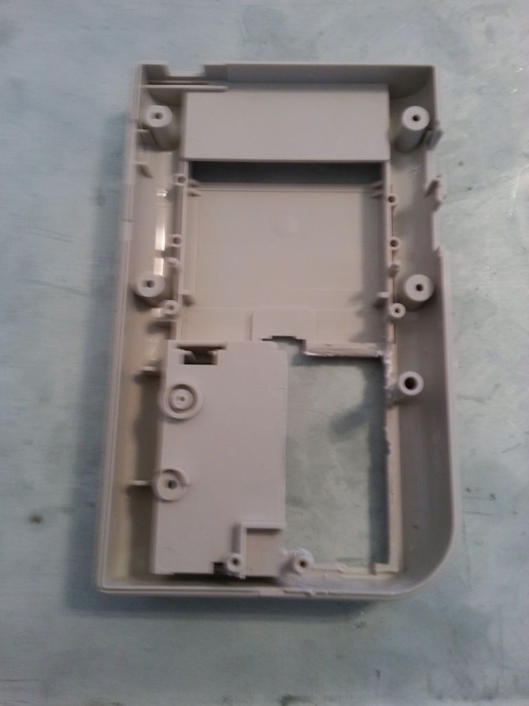
The shell of GAMEBOY is completed.
Finally dismantle the Wii remote control. Remove the four screws on the back of the remote control.
Paccari.
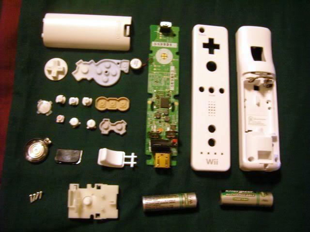
When removing all the parts and arranging it is like this.
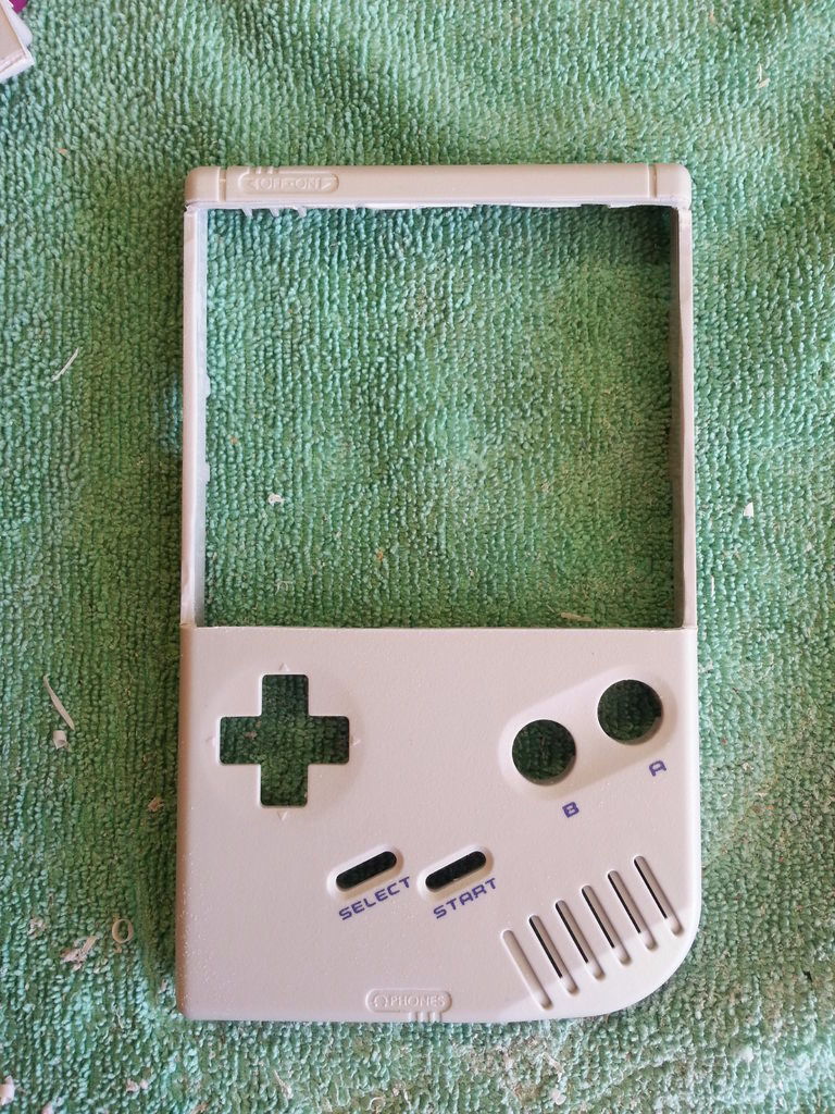
◆ 3: Top half of GAMEBOY
With this feeling, we will make sure that the smartphone holder can be attached to GAMEBOY.
Measure the size of the smartphone holder and attach the case to the free position accordingly and OK.
Cut the GAMEBOY ......
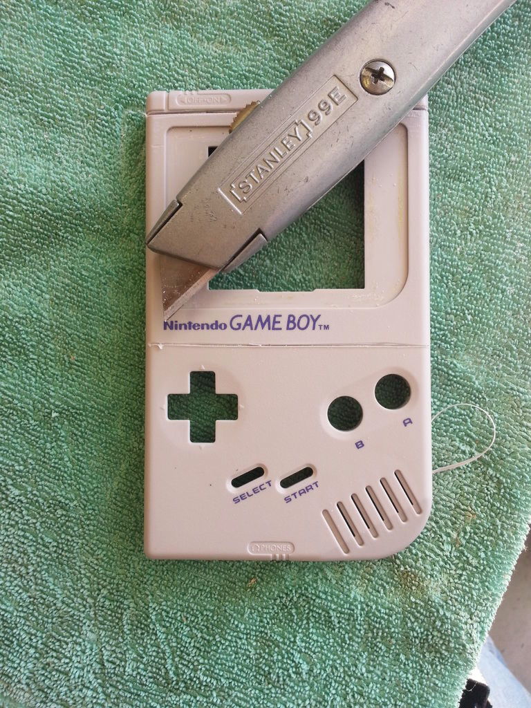
I boldly remove the obstructive part.
Author's tomatoskins seems to want to play a game with smartphone on this position.

It cuts the edge with a little file, making it easy to install the case.
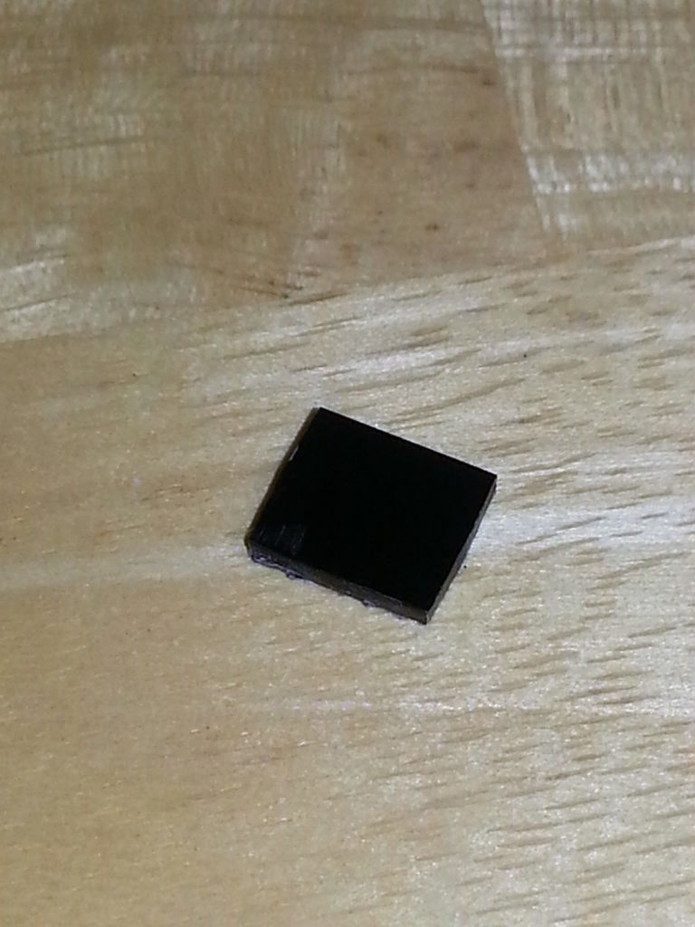
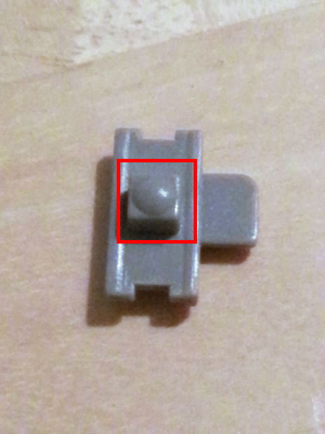
Remove the LED next to the GAMEBOY display and attach it to the lower left of the front of the unit. I made a small hole in the main body so that the light of the LED comes out on the table, I replaced the cap of BIC as a lens.
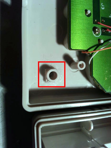
The LED emits light like this.
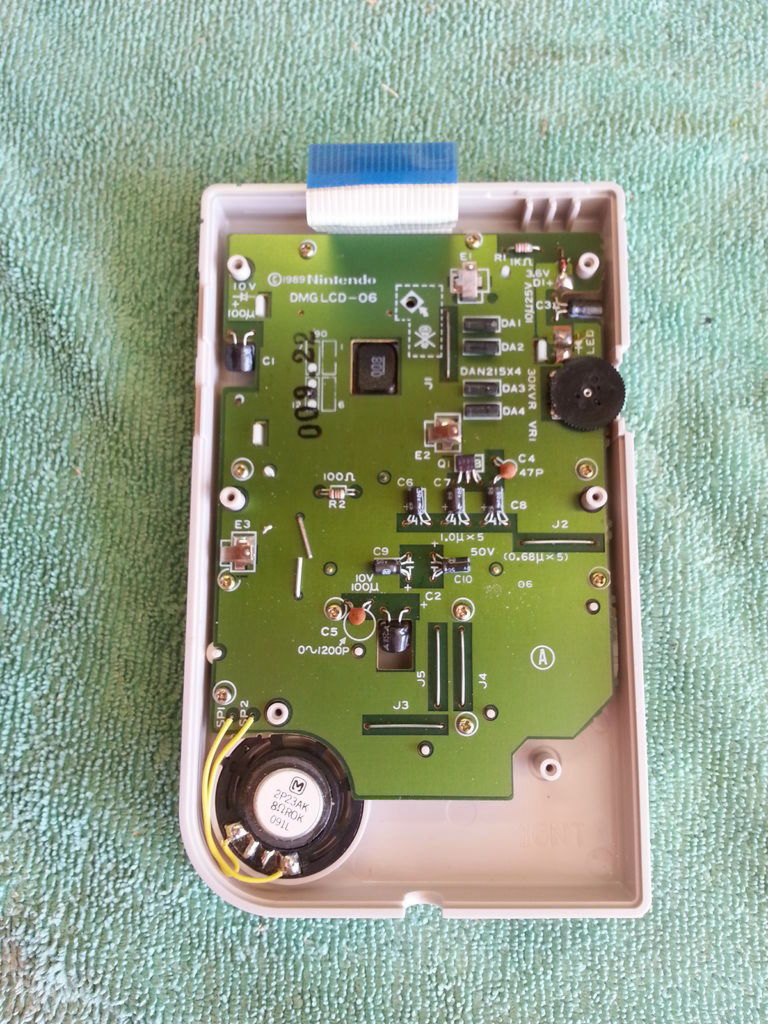
◆ 4: Front circuit
The board on the front of GAMEBOY.
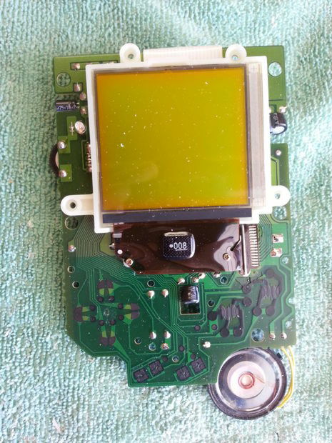
Remove this display part because it is in the way.
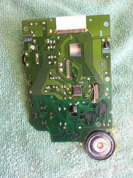
To prevent cutting the hole in the red frame part of this board, cut the board into two straight lines per line drawn in the blue frame part.
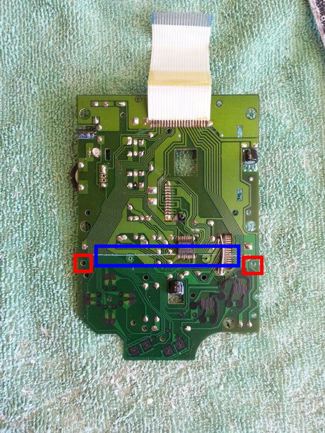
Cut completion.
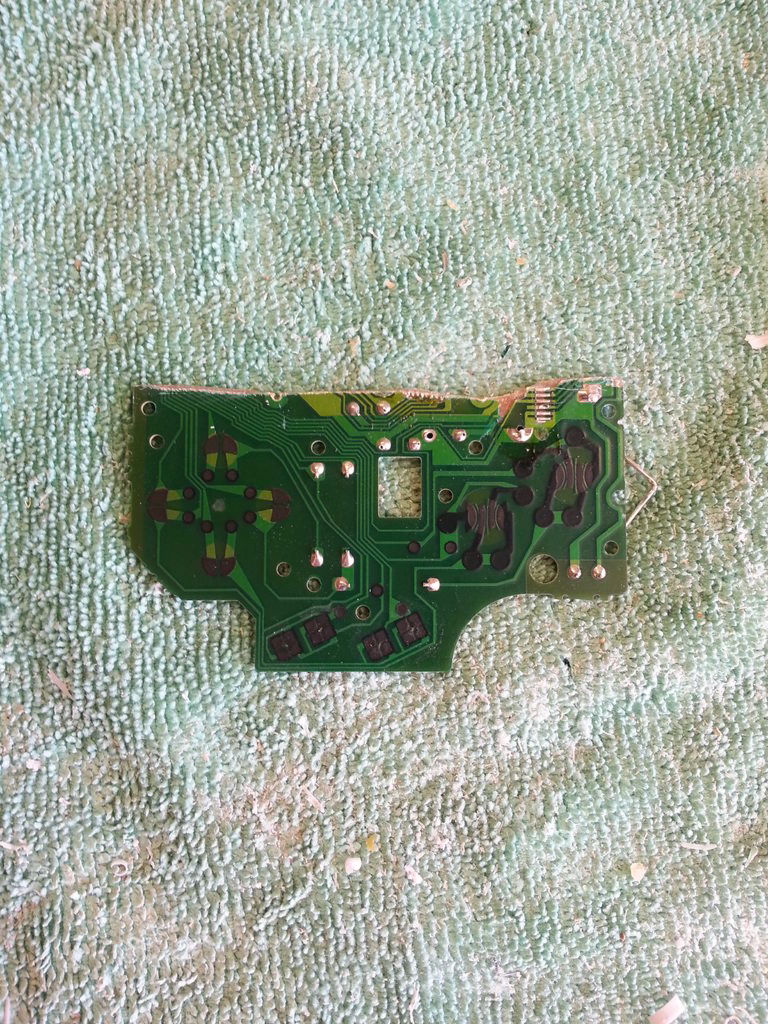
Install the small one separated this way. The reason for avoiding the hole portion is to use it as a screw hole when attaching the board to the main body.
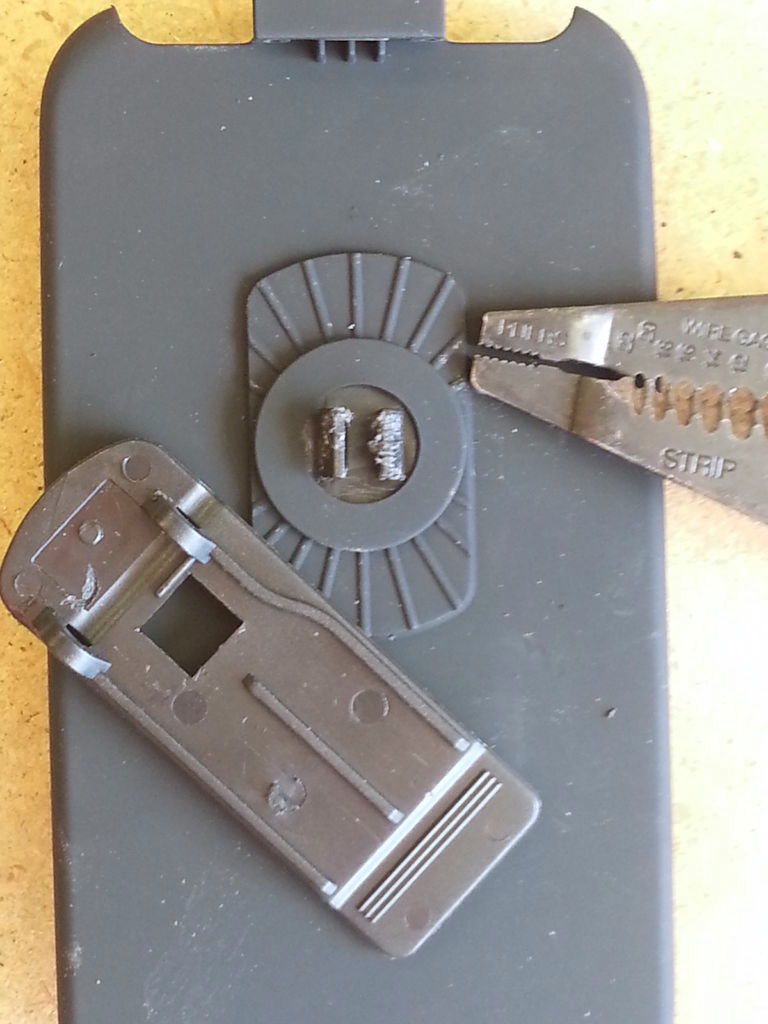
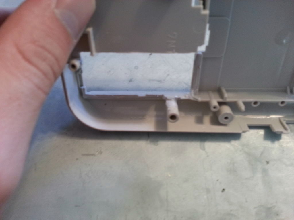
◆ 5: Rear body
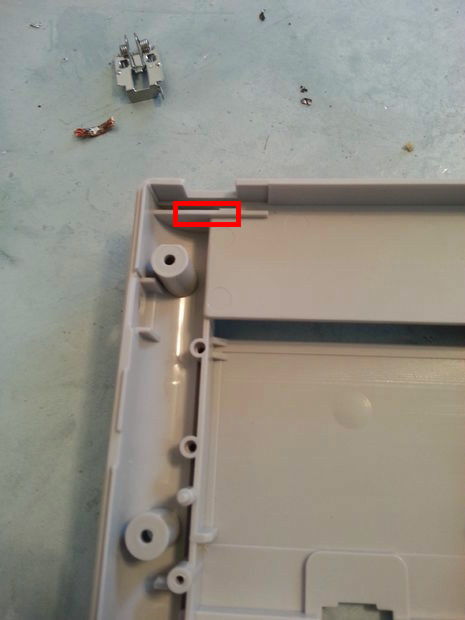
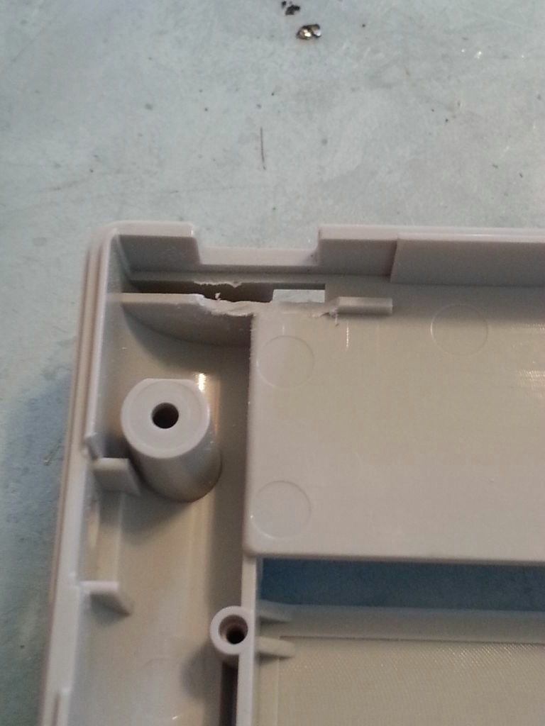
Cut the red frame part.
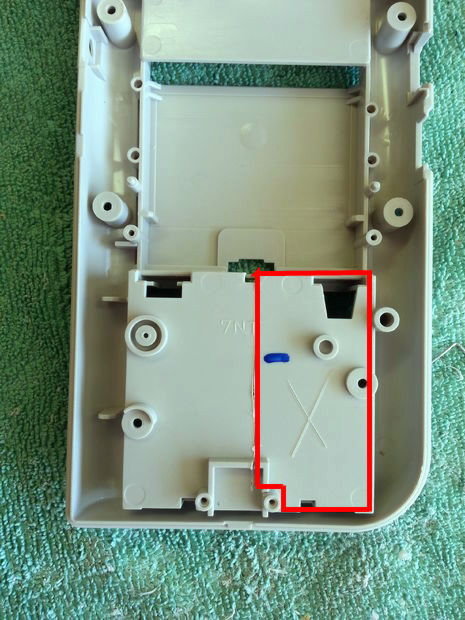
When cutting is completed it is like this. Wii remote control parts can be attached to this part
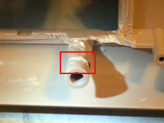
Battery box part left uncut
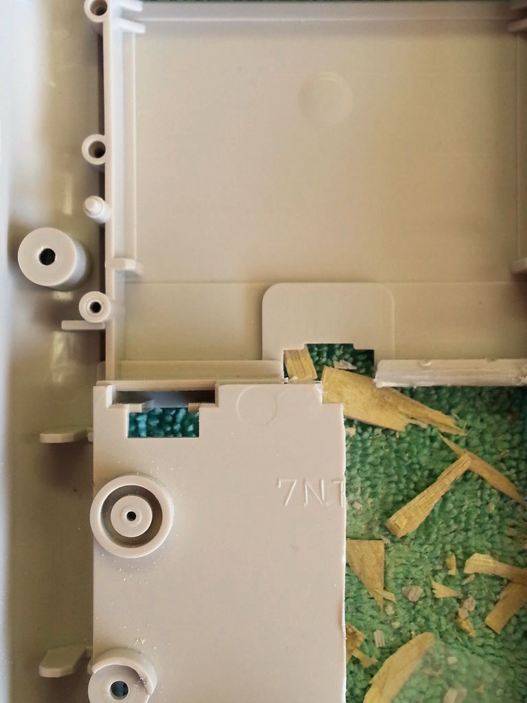
The author here put a slit, but it seems that he cut it by mistake.
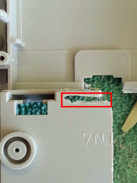
The real position of the slit is here.
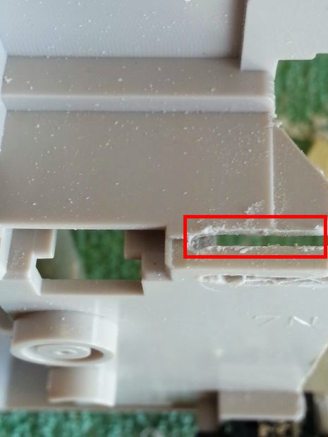
By inserting a slit, it becomes possible to set the contact metal fittings of the battery removed earlier.
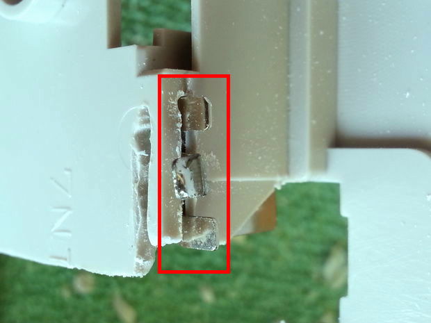
Completed the installation of the contact fittings of the battery like this.

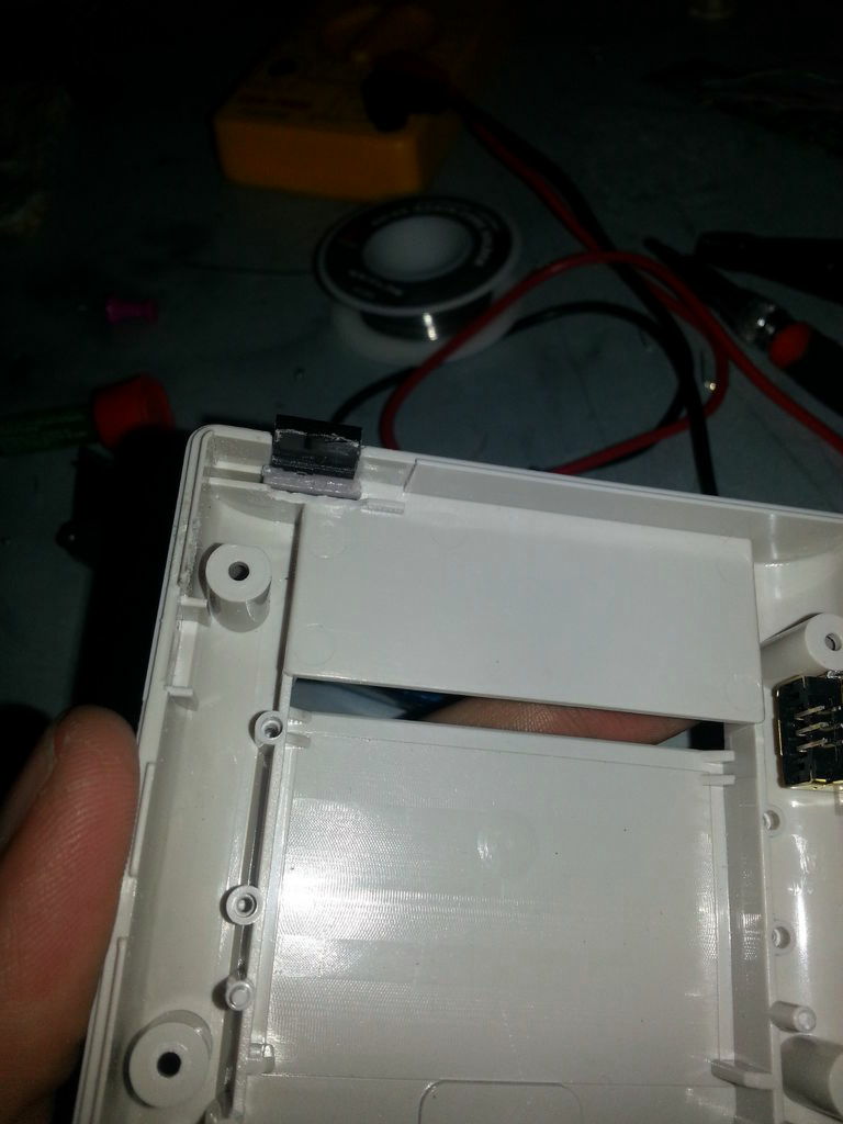
◆ 6: Removing Nunchak Port and Infrared Camera
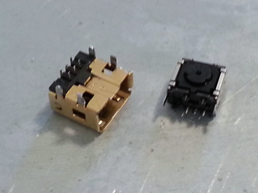
Remove the Nunchaku port and infrared camera from the board, which becomes an obstacle when setting the Wii remote control in the GAMEBOY. You can remove the infrared camera by heating the red frame part on the Wii remote control's cross key with a soldering iron.
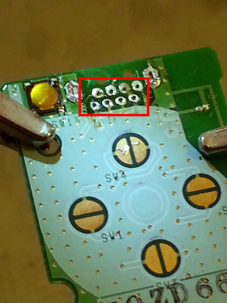
The port connecting Wii Nunchaku is opposite the infrared camera.
I will also remove this with solder.
Parts removed. The left is the Nunchak port and the right is the infrared camera.
◆ 7: Installing the Wii Remote in GAMEBOY
When installing, on the right side of the main body ......
Cut a little here.
Doing so makes it possible to mount the board smoothly.
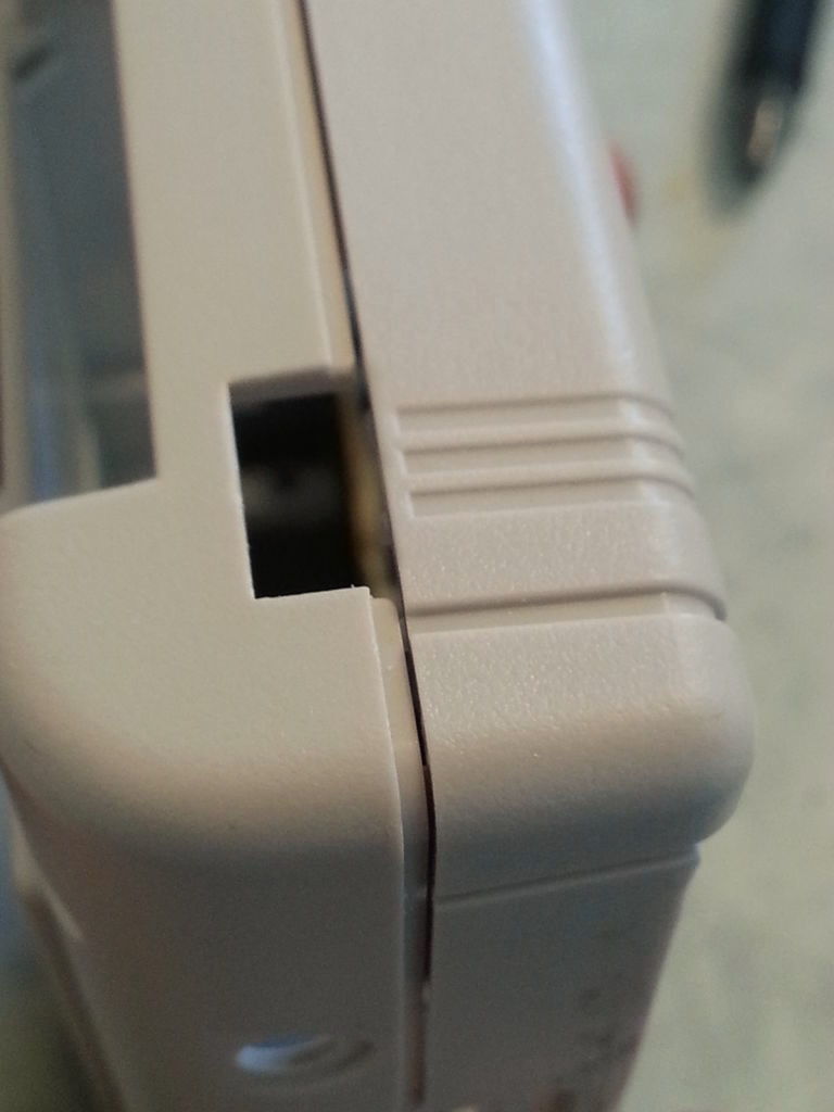
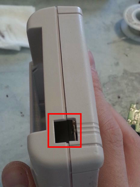
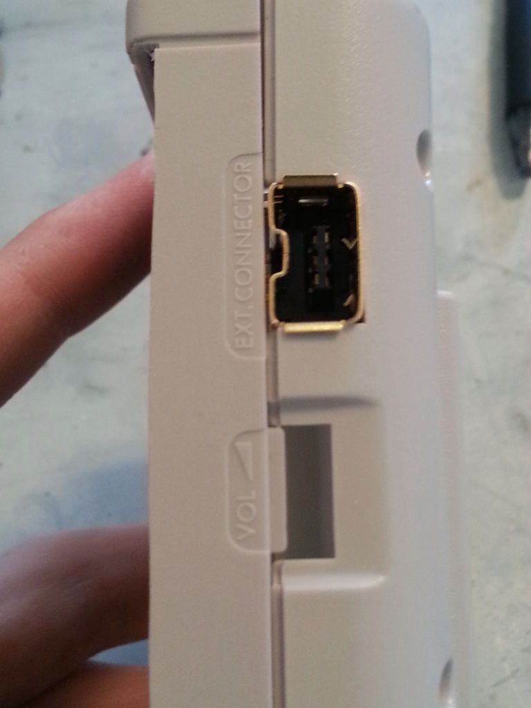
◆ 8: Create windows for infrared cameras
I will cut here.
This is OK.
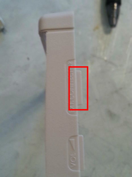
The part where the power switch of GAMEBOY was ... ...
Extend.
Plastic board (black plastic board of pointer part of Wii remote control)
In addition, cut the convex part of the power switch of GAMEBOY.
Then fix the two bonded together.

A window for infrared cameras has been created like this.
◆ 9: Porting of Nunchaku port
This claw part beside GAMEBOY body ... ...
I will scrape.
Here we have Nunchaku Port!
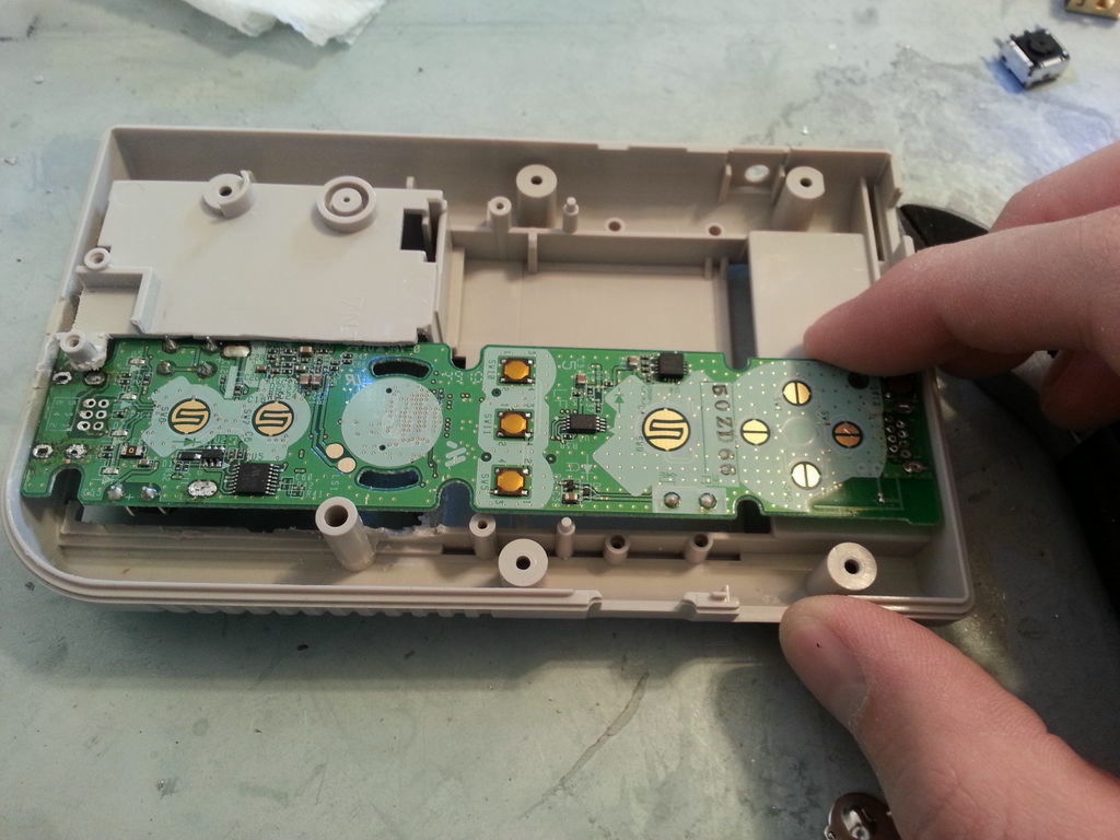
◆ 10: Install GAMEBOY's game pad
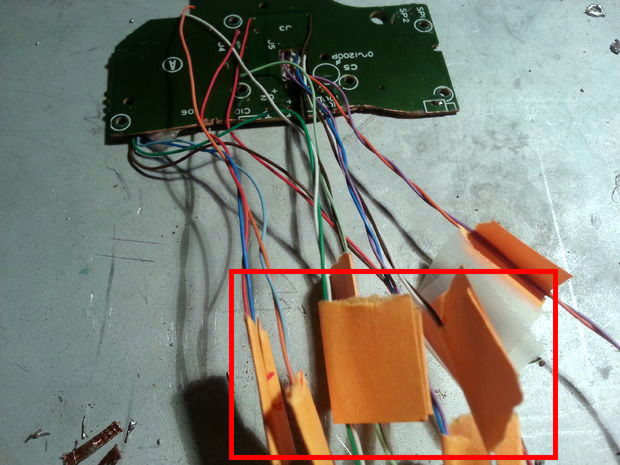
Connect the GAMEBOY button and the Wii remote control button with a wire. First of all solder the wire to the board of GAMEBOY.
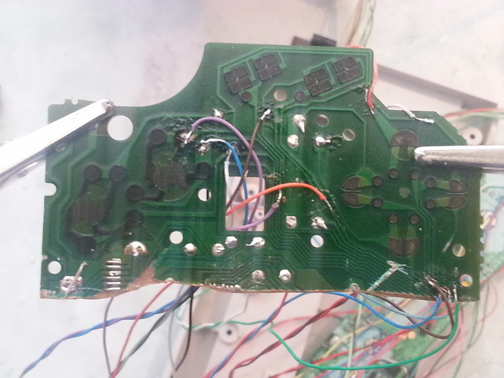
In order not to forget which line is connected with which button, pasting a label etc on the wire seems to be easier in the later process.
◆ 11: Solder the wire to the Wii remote control
We will solder the wire connected to each button of GAMEBOY to each corresponding button of the Wii remote control.
It is possible to connect the "four-way key", "1", "2", "-" and "+" buttons of the Wii remote control to the "four-way key", "B", "A", "start" and "select" of GAMEBOY . When connecting "start" and "select" buttons of GAMEBOY, "-" and "+" of the Wii remote controlLower halfConnected to.
When connecting the wires corresponding to each button, it looks like this.
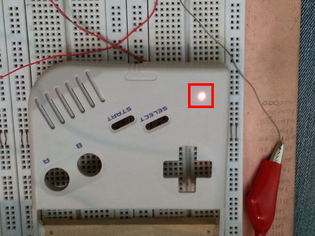
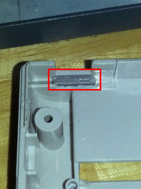
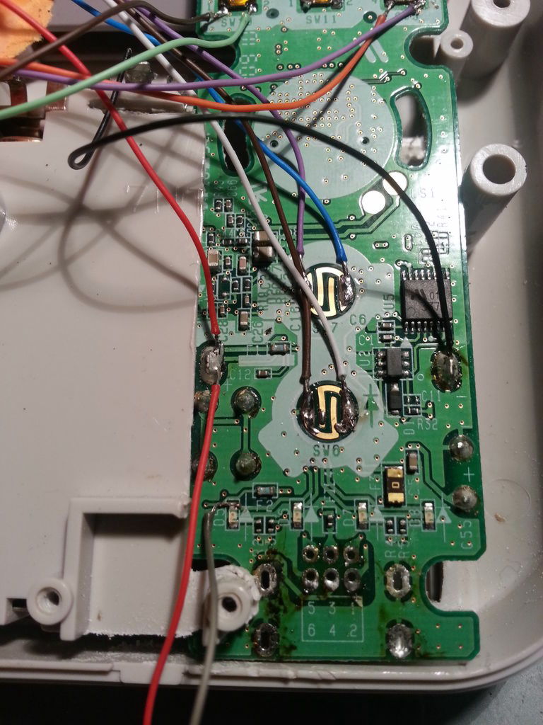
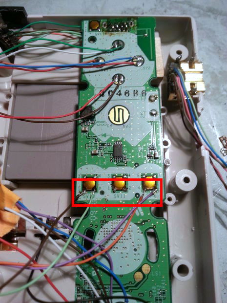
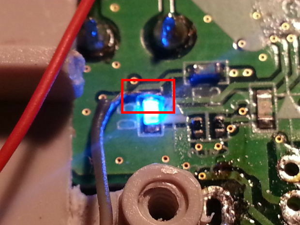
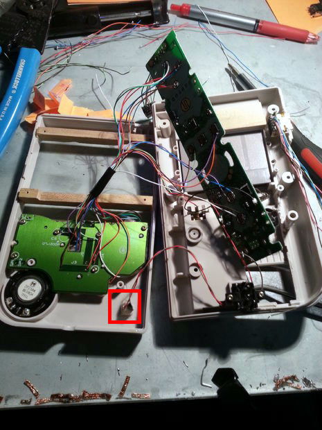
This is the LED on the GAMEBOY body.
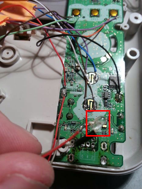
The upper red frame is the anode part of the LED that was attached to the main body, the lower one is the cathode that shines blue. Connect the anode to the positive terminal of the battery and the cathode to the negative terminal of the battery, respectively.
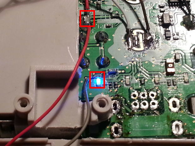
There are four places where the blue LED glows as shown in the picture, and there are four on the base of the Wii remote control (LED light to let the player know what P when playing Wii with multiple people). It seems that it will become annoying if you hide it with a tape or something.
◆ 12: Assembling
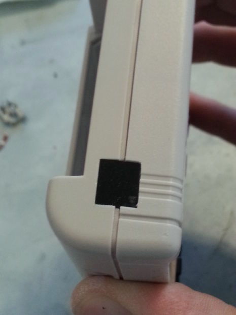
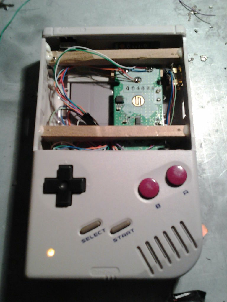
The LED light is installed in the lens part created.
With assembly like this, the LED lights on the bottom left of GAMEBOY.
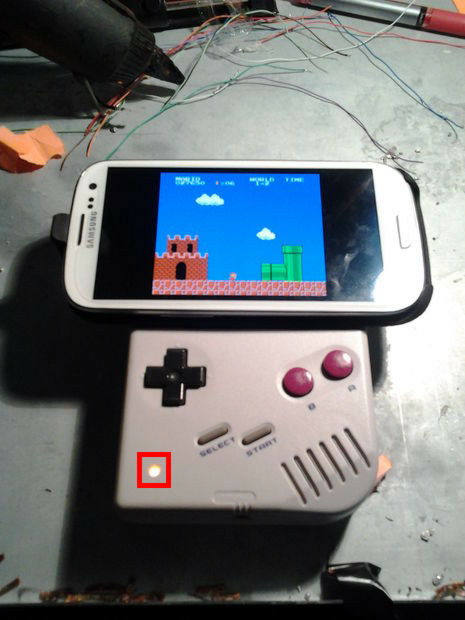
If you install a wooden frame in the empty space of the main unit so that you can attach a smartphone holder to it, even if you change the model of the smartphone, you can reuse it as soon as you change the holder.
The author's tomatoskins seems to be planning to add buttons such as "A" "B" "Home" button etc. which is not used in the Wii remote control to this GAMEBOY, and to adjust the contrast and volume of the screen .
Related Posts: