A sensor that can tell you 'where a cable is bent' will be developed
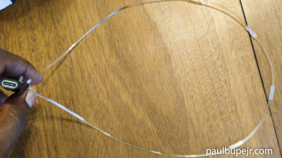
'A modular framework for surface-embedded actuation and optical sensing' by Paul Bupe Jr
https://ir.library.louisville.edu/etd/4213/
R&D Case Study: Developing the OptiGap Sensor System | Paul Bupe, Jr
https://paulbupejr.com/developing-the-optigap-sensor-system/
The idea for OptiGap came about while researching ways to effectively slow down light passing through various optical fibers. Bupe attached a 1.75mm diameter transparent filament, which is used in 3D printing, to an experimental tape measure and found that bending the tape measure and filament at a point where insulating tape was attached significantly reduced the light transmission.
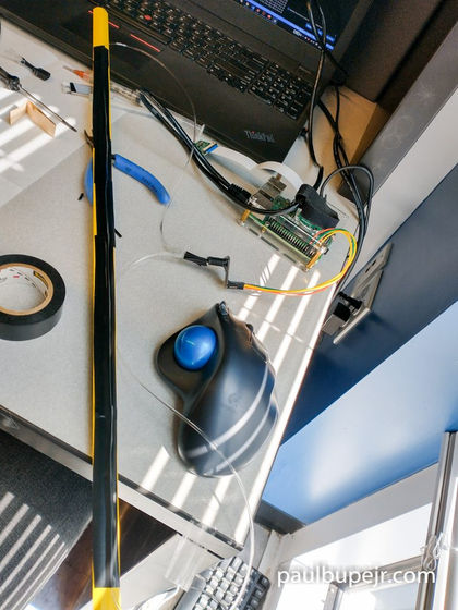
Bupe hypothesized that this result was due to sticky residue from the insulating tape stretching the filaments. To test this hypothesis, Bupe attached long lengths
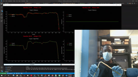
For the experiment, Buhpe used a Raspberry Pi to power the VL53L0X ToF sensor. He created a rough GUI in Python to visualize the light transmission data acquired by the VL53L0X in real time. The results of the experiment proved Buhpe's hypothesis that bending a tape measure with TPU attached would significantly change the light transmission rate.
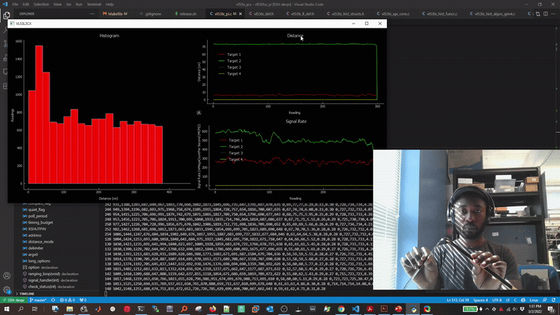
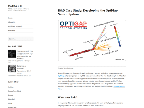
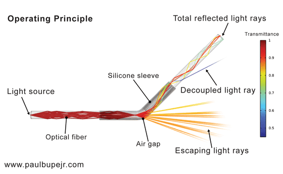
What's more, Buhpe discovered that because he could control where the light transmission fell off, he could use this to encode information about the position of the bend in the sensor. To test this, Buhpe cut the filaments and reattached them with a silicone sleeve, creating a small air gap between the filaments.

According to Bupe, when light is shone from one direction, the larger the angle of the filament bend, the more light escapes through the air gap. Bupe took advantage of this property to measure the intensity of the light that did not escape through the air gap and reached the end.
Bupe also created a filament with multiple air gaps and measured the attenuation of light transmittance when it was bent.
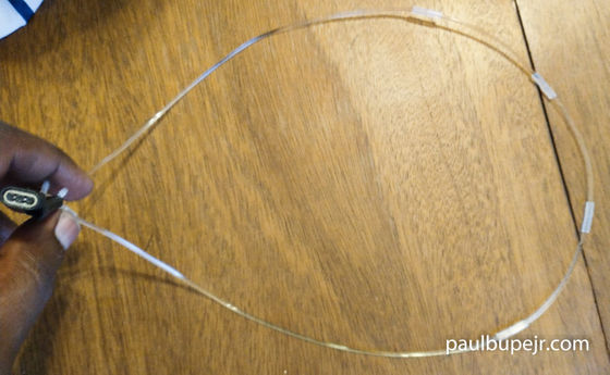
The light transmittance decreased with each air gap, and this decrease became more pronounced as the filament was bent. Based on this result, Bupe hypothesized that the air gap pattern could be used to encode information about the bend in the sensor, and
According to Bupe, the encoding of the bending position uses the '
The development of these systems, named 'OptiGap,' began with a prototype that combined three filaments into one cable, but because 3D printer filaments are large and bulky, a plastic fiber optic cable with a diameter of 500 micrometers was used instead.
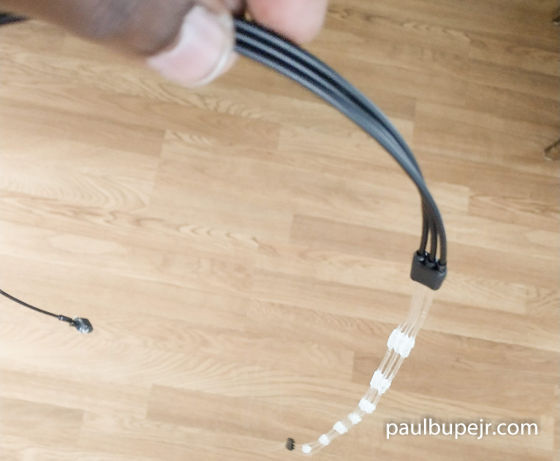
Additionally, to reduce complexity, the VL53L0X-based system was switched to a simple photodiode and infrared emitting diode setup, and a microcontroller was used to read the sensor data, resulting in a much smaller footprint than the original prototype.
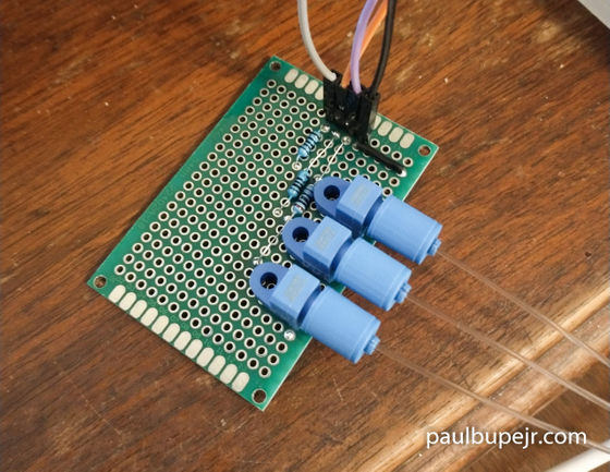
The OptiGap demo system created by Mr. Bup looks like this.

Using this system, it is now possible to numerically express the bent position of the cable.
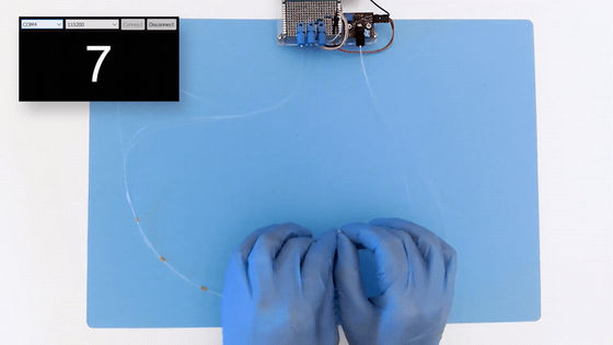
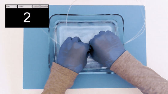
The system has also been shown to work underwater.
At the time of writing, Mr. Bupe is working on commercializing OptiGap.
Related Posts:


