What is the task of repairing the "card reader" used in the mainframe of the 1960's?
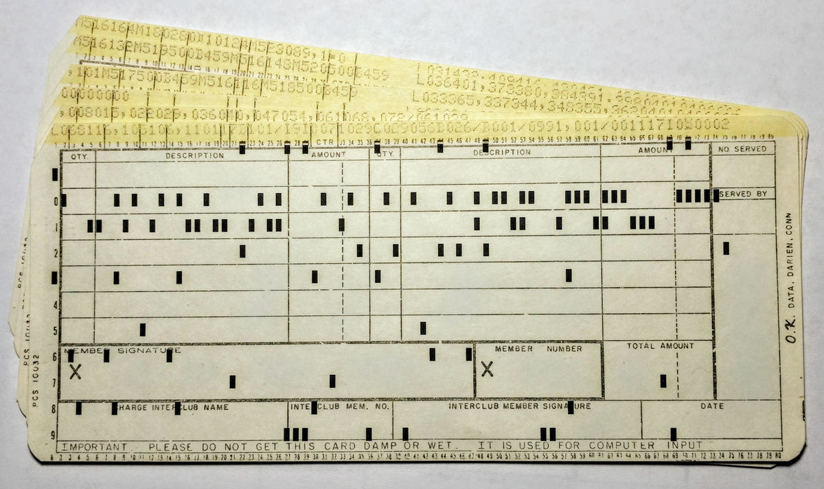
Once you enter data into the computer,Punch cardIt was used. This is a thick paperKey punch machineA hole is opened, a card reader of mainframe makes punch card read, and data is input to the computer. I am doing repair work and maintenance of old computerKen SirifMr. Mainframe developed in the 1950'sIBM 1401I wrote a blog about what I used to repair the card reader used for.
Repairing the card reader for a 1960s mainframe: cams, relays and a clutch
http://www.righto.com/2018/02/repairing-card-reader-for-1960s.html
The card reader repaired this time as an accessory of IBM 1401Computer History MuseumThings that were in the collection. The IBM 1401 was a mainframe that was operated to conduct payroll accounting and inventory management in the 1960s, and it was a popular mainframe where over 10,000 units were produced.
Recording of data etc was drilled in the punch card and recorded, and the card reader of the IBM 1401 was able to read 800 punch cards of 1 sheet 80 columns, that is, 13 sheets in 1 second. Considering that the process of "recognizing 80 rows of holes opened in the inserted card and stacking the processed cards in the center card storage place" was done by a mechanical mechanism, the inside becomes a rather complicated mechanism You can imagine it is. The card reader says that physical problems such as paper jams often occurred due to a mechanical mechanism. When a problem occurred, the error lamp lights up and it seems that the engineer was doing recovery work immediately.
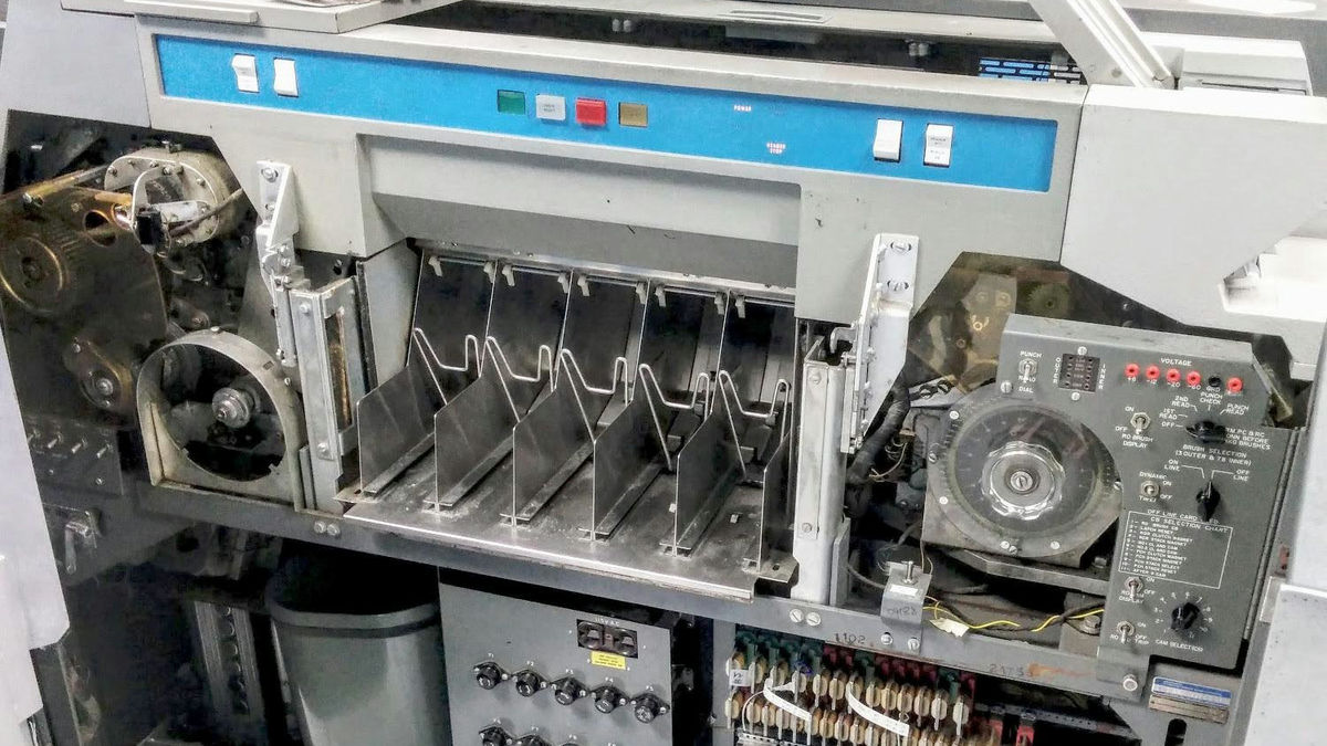
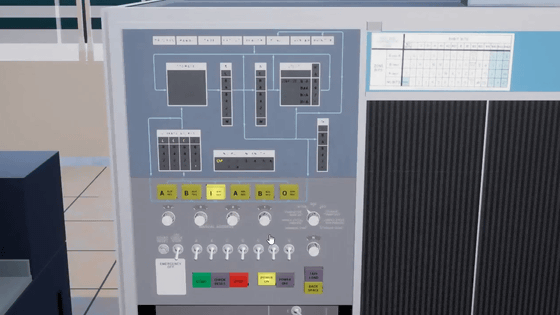
This is the IBM 1401 card reader / key punch machine with the front door removed. The right half is the card reader and the left half is the key punch machine. In the card reader, the punch card which recorded the data is inserted from the right side of the machine, passes through the metal brush which reads the hole of the card, moves to the center of the machine, and finally the card storage place in the center of the image It is a mechanism that falls to. The left side of the machine is a key punch machine that punches holes in the punch card, and the bucket in the lower left gathers the garbage of the punch card issued by the key punch machine. When the bucket was filled with garbage in the punch card, the warning light shone and the engineer said that the contents of the bucket were thrown away by the engineer.

The IBM 1401, which was in the computer history museum, said that the card reader did not work well for several months and the lamp indicating "stop the leader" began to light up. It is natural that card readers who have been manufacturing for nearly 50 years have failed, but those working in the computer history museum tried to solve the problem.
A staff member in charge of the IBM 1401 repeated the experiment, and it turned out that the problem was in the process of the card reader. Just by having the card read only by hundreds of punch cards did not have any problems when printing the data with the line printer of the external device which outputs the input data, although the first three sheets could be processed without trouble, It seems that the "Leader Stop" lamp surely lights up on the fourth sheet.
The card reader can read 800 punch cards in one minute, but line printers can print 600 lines per minute in one minute. When reading the punch card and the output of the line printer repeatedly, there is a gap between the card reader side and the line printer side. Therefore, the card reader incorporates a system that causes a delay when reading the fourth card, but this delay seems to have caused an error. The mechanism of the card reader verified the process of lighting "Leader Stop", and as a result, it turned out that there was a problem with the clutch causing delay in card reading.

The card reader operates with a 1/4 horsepower electric motor, and the motor powers gears, belts, rollers and cams. In this state, there is a gap between the reading of the card and the printing by the line printer, causing problems, but it is possible to operate stably by generating a delay by the clutch.
In a card reader that reads cards at high speed, the clutch needs to switch at very fine timing. The card reader has a function to check that the clutch operates normally, so the clutch operates only when the operation of the clutch meets the requirements of the card reader. This time the "Leader Stop" lamp lights up because the clutch mechanism malfunctioned, so the clutch could not perform the operation requested by the card reader, it stopped.
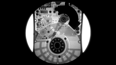
A mechanism called "dynamic timer" confirms the clutch angle of the card reader at the time of maintenance. This is a type of oscilloscope, a plastic disk labeled at an angle of 0 degrees to 359 degrees, the neon ball rotating in conjunction with the rotation of the clutch glows to indicate the angle. The engineer reads the labeled angle on the disc and measures the angle of the clutch.
As a result, it was found that the angle of the clutch was deviated by about 5 degrees as compared with the normal case. In order to operate normally, it is said that the deviation should be within 0 to 2 degrees, and the restoration member starts the work of correcting the angle of the clutch.
When I examine it, I find that the cam is firmly attached to the gear. Due to the fact that it was kept in a damp warehouse for decades, the members carefully knocked the cam with a hammer and managed to peel off the gear and cam in any way. After adjusting the angle and moving it again, an error also occurred for some reason.
I checked the angle with the dynamic timer again to investigate the cause, the clutch was still deviated by 5 degrees. Although it was a member who wondered as "Why should you calibrate the cam properly by measuring the angle properly?", Apparently the cam which is the cause of the clutch's angle deviating is corrected, but it is linked by the first cam which is displaced It turned out that the angle of the cam was also misaligned. Since the card reader is a mechanical mechanism, if there is a problem in one place, trouble may occur in another part linked with it.
Members changed the angle of another cam as a result, the card reader now works normally.

Ken said that academic thanks to them that nearly 10 engineers were involved in the repair work of the card reader. Also, through repair work, I could see machines such as old-fashioned cams, gears, motors, etc. There were different interests from software restoration work.
"With this work, I understood the various mechanical systems of the card reader, it can be fully utilized for future maintenance and it seems to be useful for prevention of breakdown in advance," Ken said It is.
Related Posts:


in Hardware, Posted by log1h_ik