What is special about involute gear shapes?

Gears are divided into two types
A 15-minute intro to involute gears - lcamtuf's thing
https://lcamtuf.substack.com/p/a-15-minute-intro-to-involute-gears
Gear design may seem simple at first glance, but in reality it requires deep knowledge of mechanical engineering and material science, as well as proper design using mathematical formulas and CAD tools. A properly designed gear, based on this knowledge, rotates at a constant speed while reducing friction and vibration, ensuring smooth transmission of torque.
Before explaining involute gears, lcamtuf first explains the basic principles of gears.
For example, a 'rack' is a straight bar with teeth. A rack is used to transmit linear motion to another rack, and the teeth mesh to transmit power. The simplest type of rack with straight teeth has the advantage that there is no risk of slippage, but the disadvantage is that mechanical stress tends to concentrate at the base of the teeth.
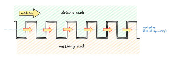
Racks with diagonal teeth are stronger than racks with straight teeth, but because the force vector on the meshing surfaces is at an angle, insufficient friction or too much play in the assembly can cause the gears to slip.
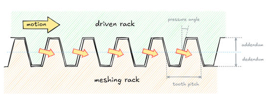
Generally, the optimum 'pressure angle,' which is the angle between the force vector between the meshing tooth surfaces and a line perpendicular to the direction of rotation of the gear, is considered to be 15 to 25 degrees. Low pressure angles are used in precision equipment because they can operate properly even if the gears are not properly aligned. High pressure angles are also characterized by their ability to withstand very heavy loads.
Racks are often used in combination with a circular gear called a 'pinion.' In order for the rack and gear to mesh without slippage, the gear must rotate the same distance along its 'pitch circle,' which determines the pitch of the teeth, every time the rack moves a linear distance.
Next, extra teeth are added to the gear to match the tooth depth of the rack, which lcamtuf explains is typically equal to the tooth pitch divided by pi. Once the pitch circle and extra tooth depth are determined, the rack is used as a virtual cutting tool to gradually remove material from the gear, rotating the gear the same amount along its pitch circle every time the rack advances.

This process creates a shape with a single point of contact at each tooth on the rack. This shape is called an 'involute curve.'
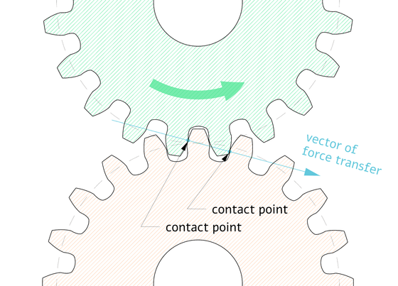
Since the involute curve always contacts the rack teeth at a constant angle, an involute gear with an involute curve always rotates at a constant speed regardless of the position of the rack teeth. Also, the formed involute gear can mesh with other gears that have the same pressure angle, tooth pitch, and tooth depth, giving it the advantage of being highly versatile.
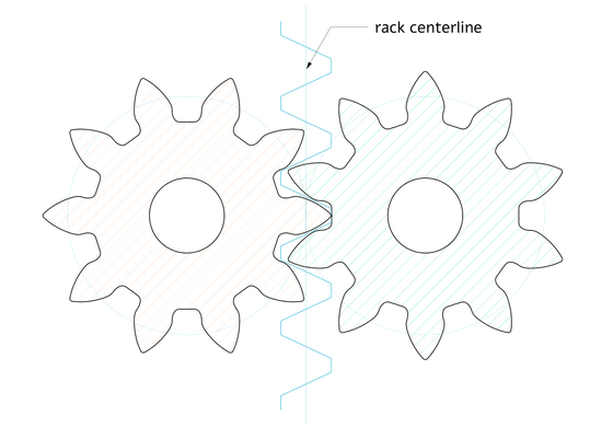
However, when forming the tooth profile of an involute gear, if the number of teeth formed is small, the approach angle of the cutting tool becomes large, and the root part of the tooth is cut away more than necessary, resulting in a problem called 'undercut.' When undercut occurs, the strength of the tooth is reduced, and in the worst case, the involute curve is damaged, and it is said that the gear's function may be lost.
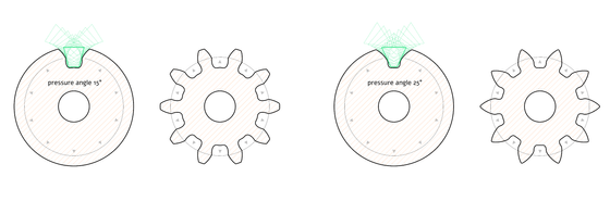
One design technique to reduce undercuts is to 'increase the pressure angle.' Increasing the pressure angle moves the cutting tool's cutting edge away from the center of the gear, reducing interference with the base of the teeth. However, a larger pressure angle can also cause problems, such as making manufacturing more difficult.
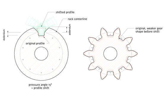
Another method that has been proposed is 'profile shifting.' This is a method in which the cutting tool is moved upward relative to the center of the gear to reduce undercuts. Profile shifting makes the base of the teeth thicker, improving their strength. However, a disadvantage of profile shifting is that gears that have been profile shifted can only mesh with other gears that have been profile shifted in the same way.
Related Posts:
in Science, Posted by log1r_ut
