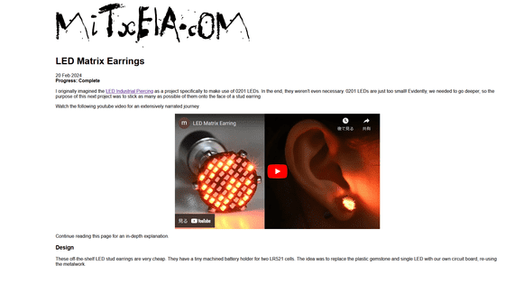
How to modify commercially available earrings to create earrings equipped with LEDs that can control the way they light up?
LED Matrix Earrings - mitxela.com
https://mitxela.com/projects/ledstud
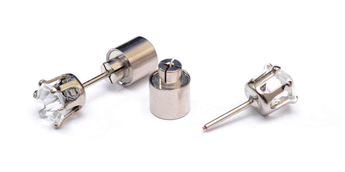
Mr. Mixtela modified the plastic accessory to glow with an LED powered by an LR521 standard button cell battery. Mixtela explains that they kept the original accessory, but replaced the jewels and LEDs with their own unique pieces.
The circuit and firmware used to emit and control the LEDs are said to be the same as those used in badges created using a
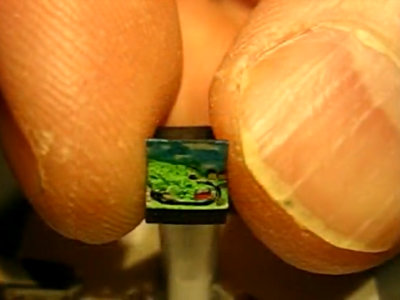
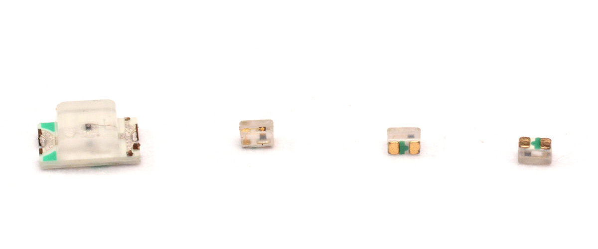
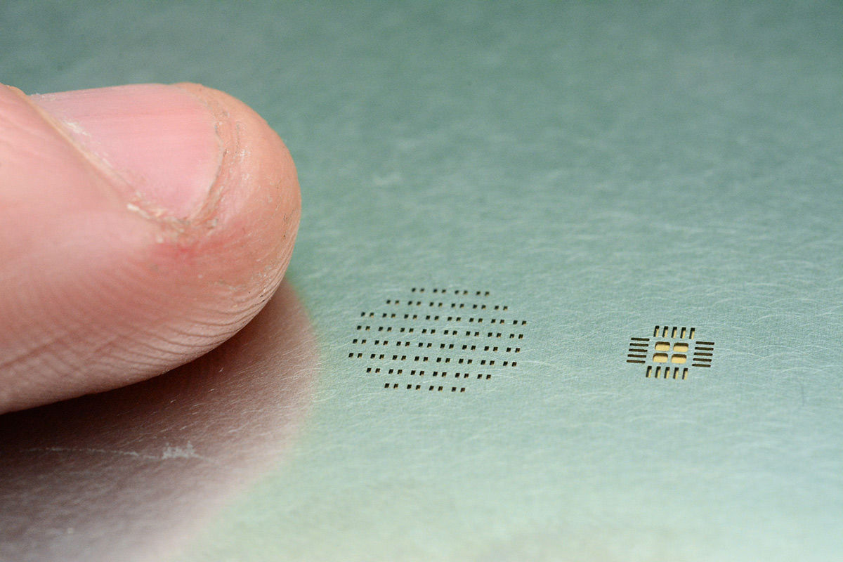
Previously, the badge created by Mr. Mixtela had a distance of 3 mm between each LED, but for this piercing, this distance was narrowed to 1 mm, successfully reducing the area of the badge to about 1/9th. doing. Mr. Mixtela was also particular about not having a border around the board, which he recalls as ``a big challenge.'' Below is an image comparing the size of a general LED and the LED used this time. You can see that the LED used this time is much finer than the general LED on the left.
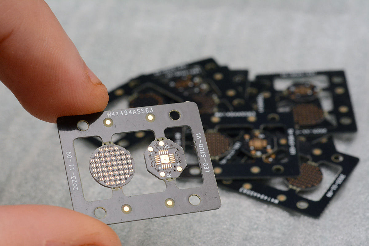
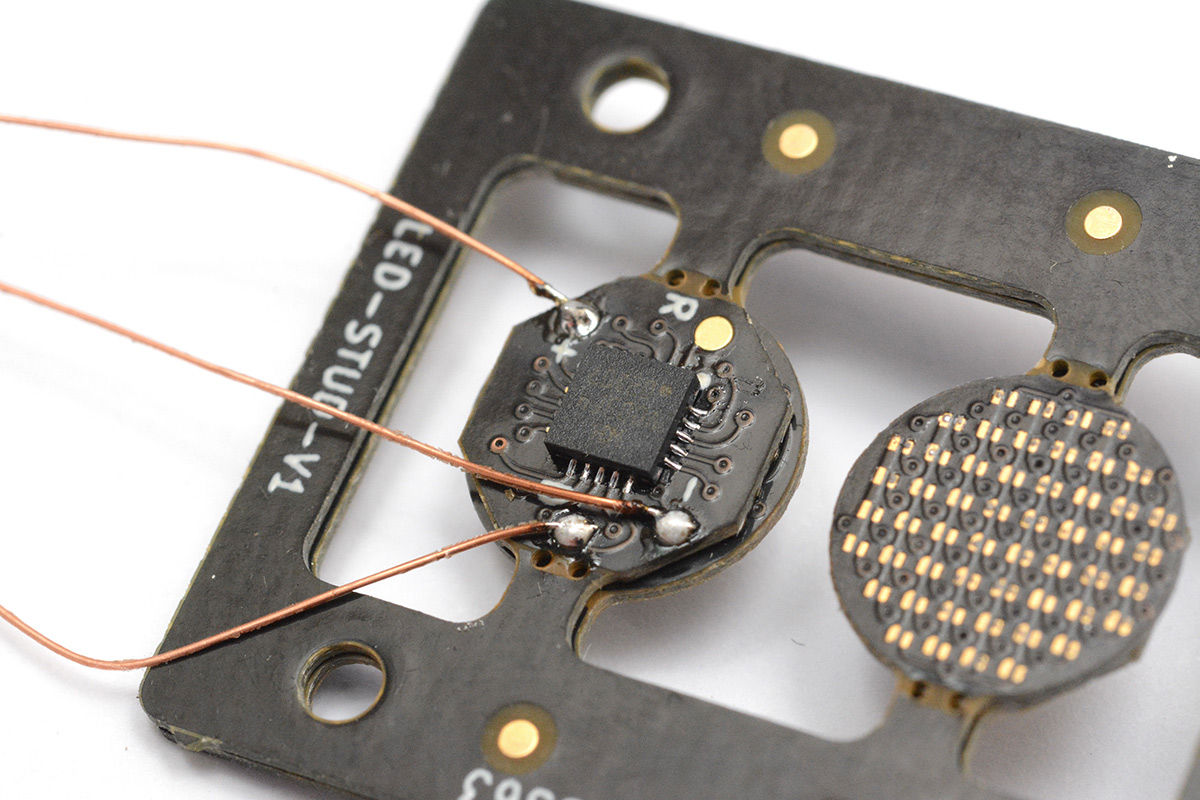
Mr. Mixtela also ordered a unique circuit board that can sandwich LEDs.
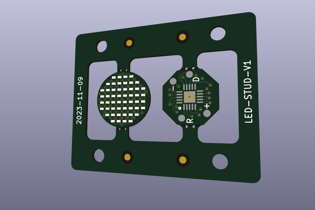
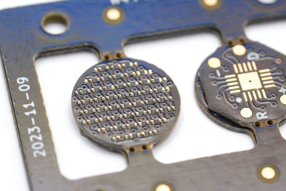
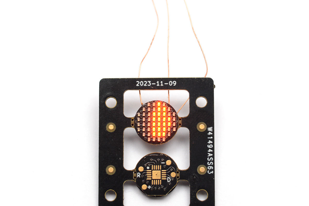
The back side of the circuit looks like this. According to Mixtela, the diameter of
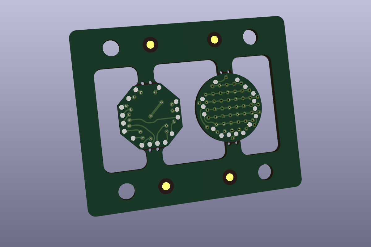
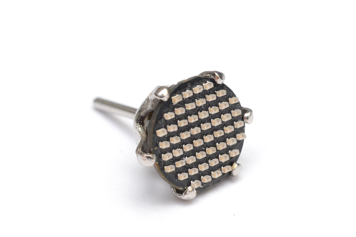
The main display on the front of the earrings will have approximately 52 LEDs in a 9mm diameter circle.
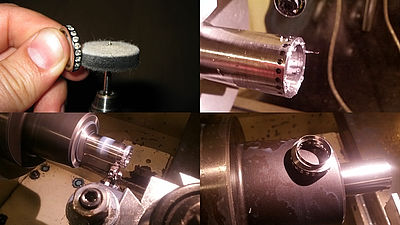
Mr. Mixtela introduced steel stencils to improve the efficiency of LED soldering work.
However, they cited problems such as ``Because I didn't use the stencil as a reference, I had trouble aligning it,'' and ``I made the vias for installing the LEDs too small, which made the stencil work stressful.''
Next, Mr. Mixtela managed to complete the soldering work to the board, despite having problems such as ``the LED position shifts due to shaking during soldering''.
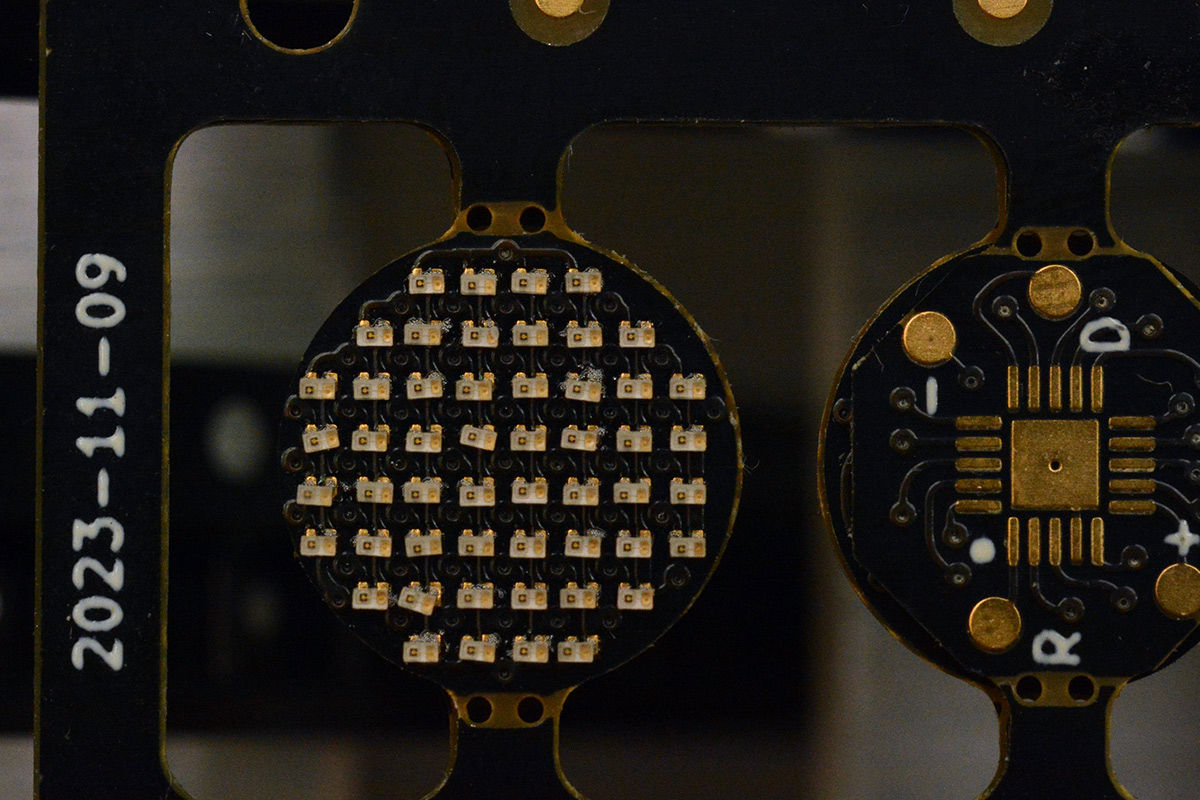
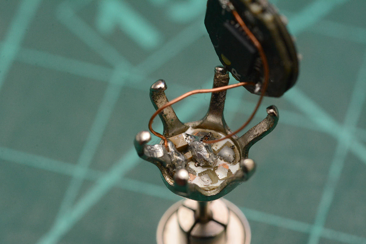
Mr. Mixtela, who adjusted the angle of the LED, wired the cable on the back of the board. Mixtela recalls, ``Wiring on the back of the board wasn't that difficult.''
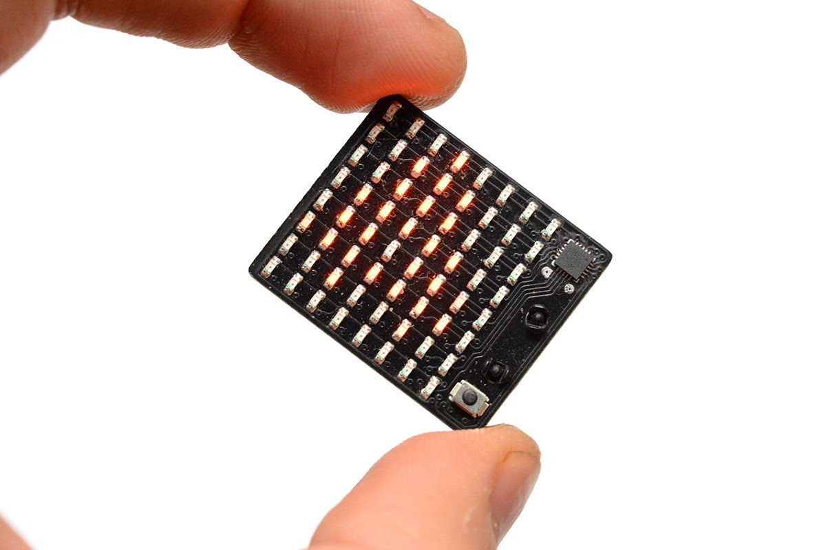
After checking the operation, the LED lights up successfully. Mixtela removed the completed board from the surrounding frame.
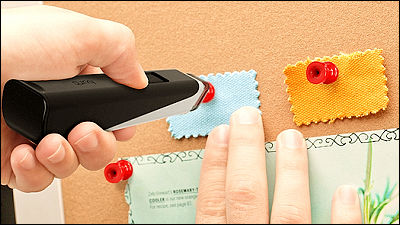
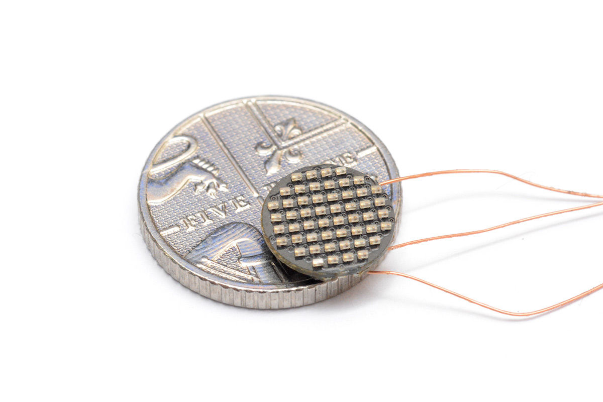
Below is an image comparing a 5 pence coin with a diameter of about 18 mm and the created unit.
When you remove the base earring jewelry, a detailed circuit board is installed.
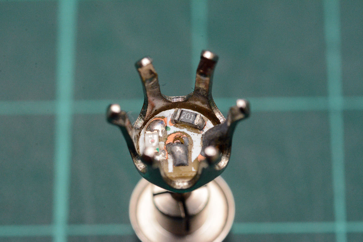
Initially, Mixtela simply soldered the units he had created onto this circuit board. However, it seems that it did not start properly due to issues such as the firmware used for control having too high power consumption.
So Mixtela solved this problem by adding a capacitor to the circuit. The power consumption of the entire unit was only 8mA.
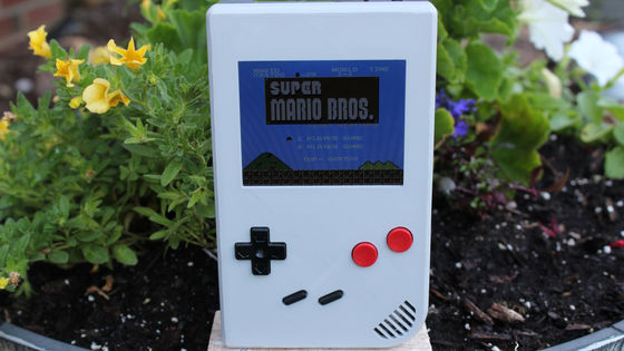
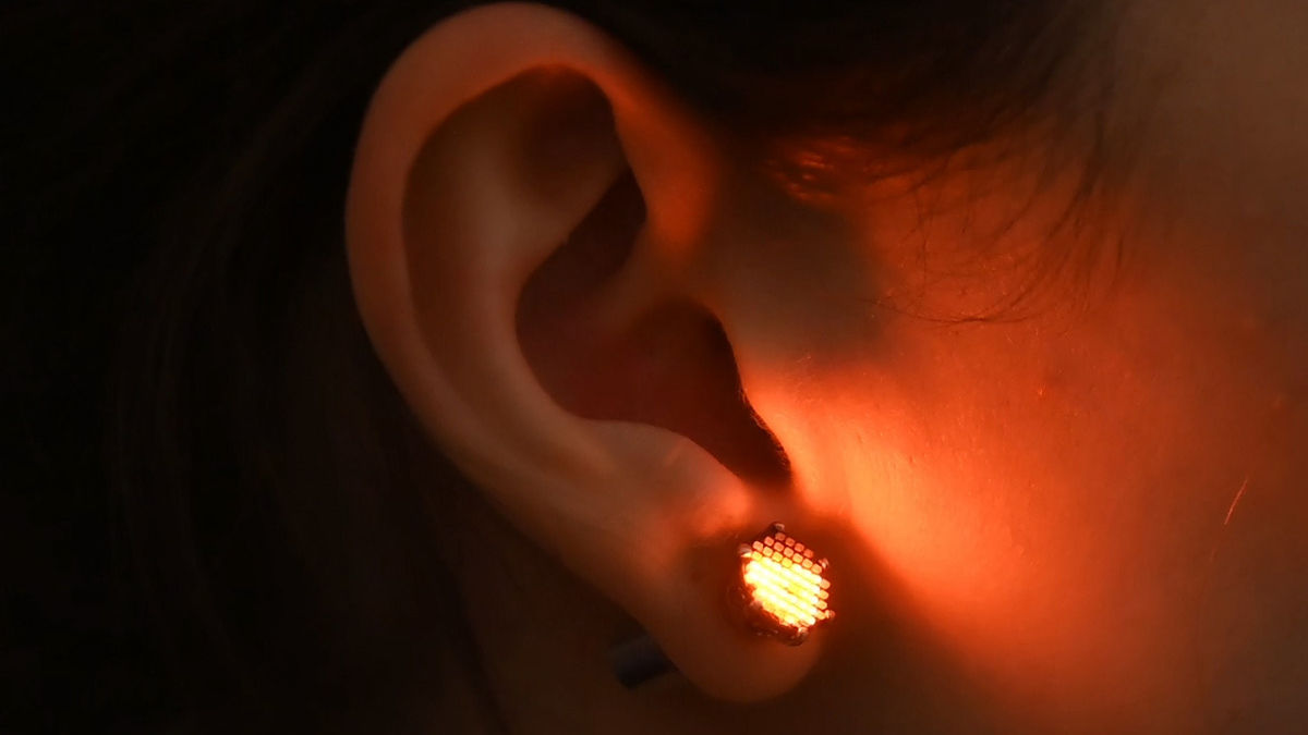
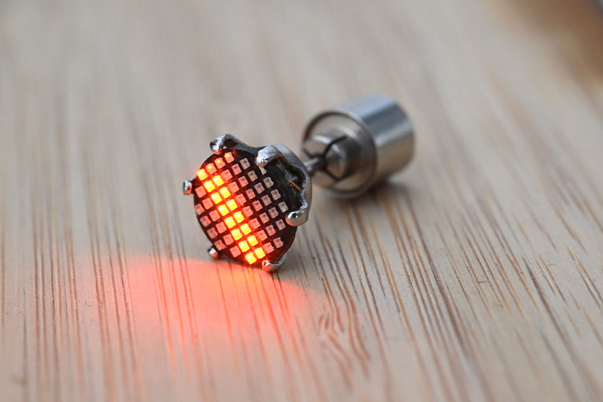
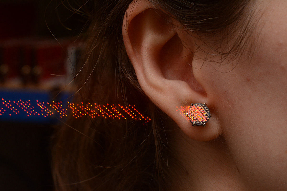
This is what it looks like when you actually shine the earrings.
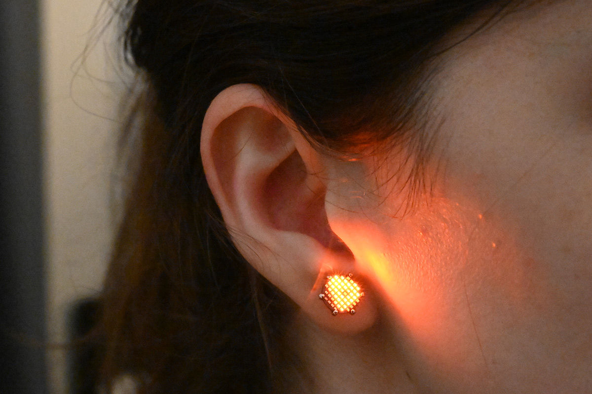
The size is perfect to fit your earlobe.
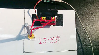
It is also possible to photograph the trajectory of light by exposing the camera for a long time.
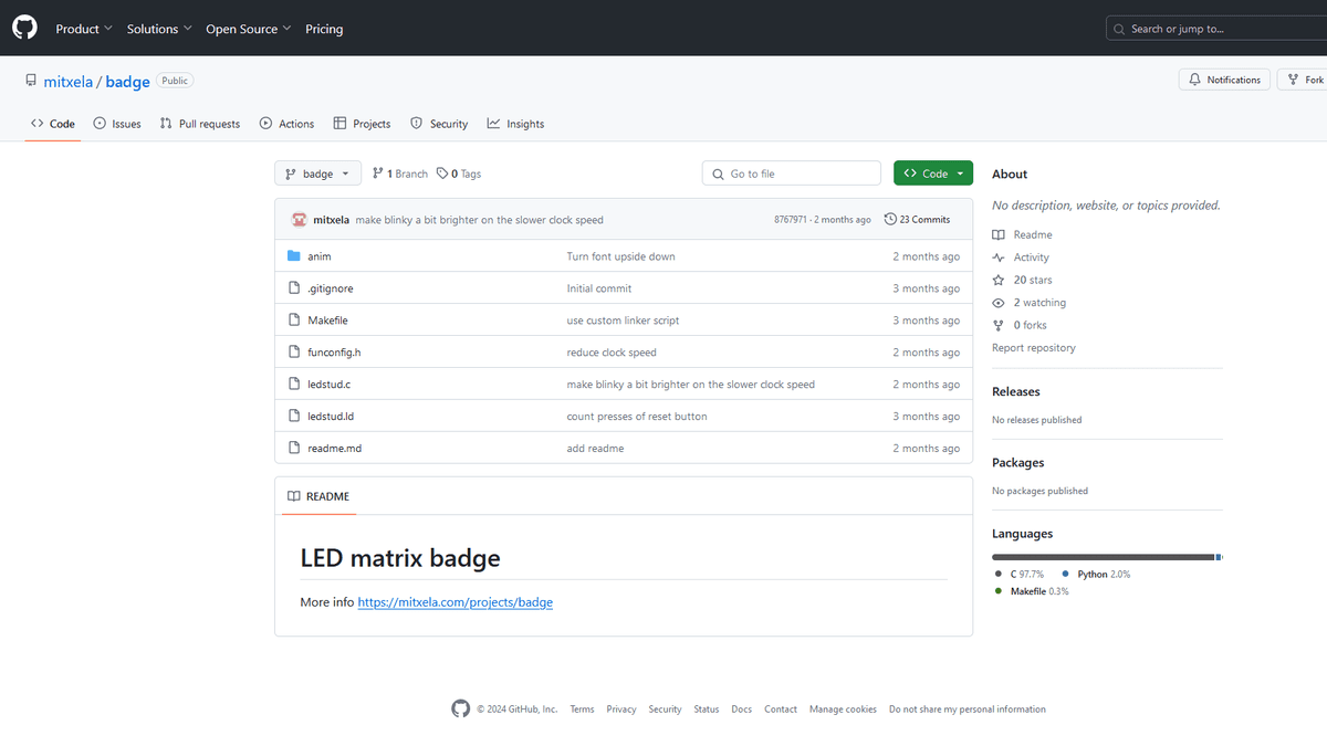
The source code of the firmware used for this piercing is available on GitHub.
GitHub - mitxela/badge
Related Posts: