An engineer who made a game machine by himself released the production procedure and circuit diagram
Software consultant Craig Bishop, a portable game machine ` ` Gameslab '' that can download and customize the system of each game machine instead of emulating the game machine system on a PC like an emulator, Is developing. Bishop's
Gameslab project overviewCraig J. Bishop
https://craigjb.com/2019/11/26/gameslab-overview/
◆ What is Gameslab?
According to Bishop, Gameslab is a game console based on the SoC Zynq-7000 that combines software programmability of an ARM-based processor with hardware programmability of an FPGA , designed with open source KiCad . The feature of Gameslab is that by downloading a system that matches the platform of each game or application, you can customize the specifications of the game console itself and play the game. For example, if you are playing a 2D scrolling shooter, you can download a system that implements on-screen sprite drawing settings and animation acceleration that are appropriate for the game. In addition, if you play Game Boy software, instead of emulating the Game Boy CPU and peripherals with software like an emulator, download the Game Boy specification to the FPGA and install the Game Boy system in Gameslab It seems that it can be mounted.
◆ Configuration of Gameslab
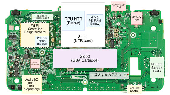
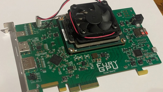
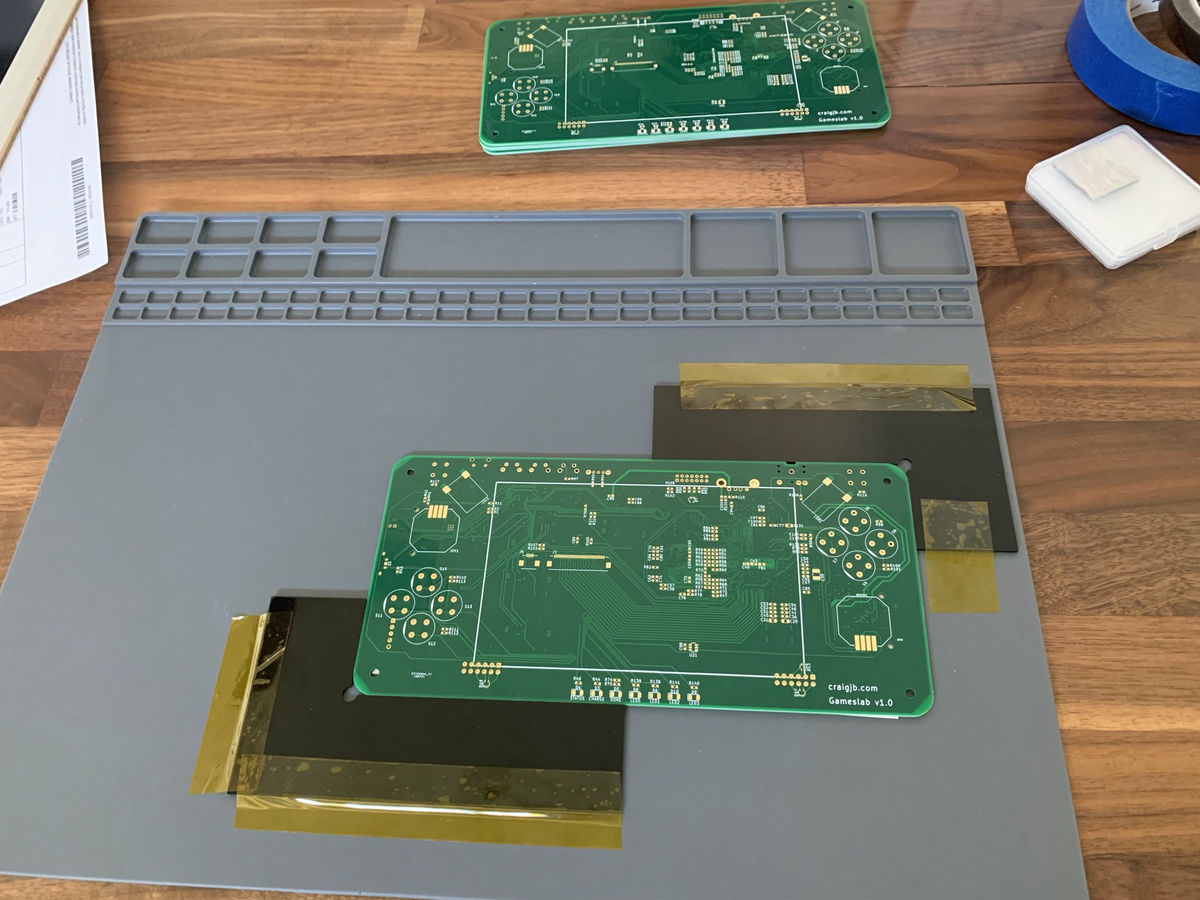
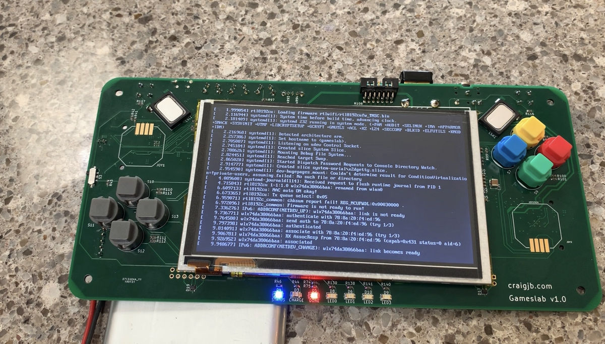
The following image is the Gameslab board. Gameslab is made up of about 360 parts.
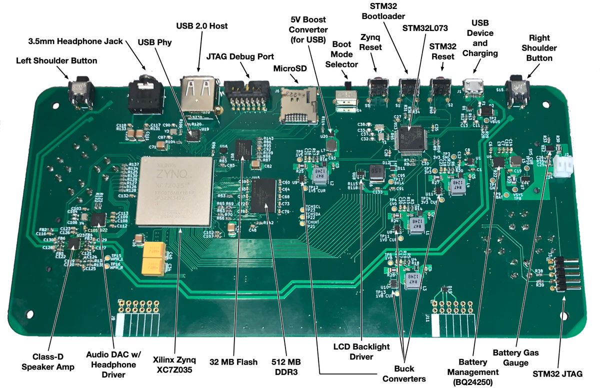
Gameslab has a lithium polymer battery that is charged from MicroUSB. According to
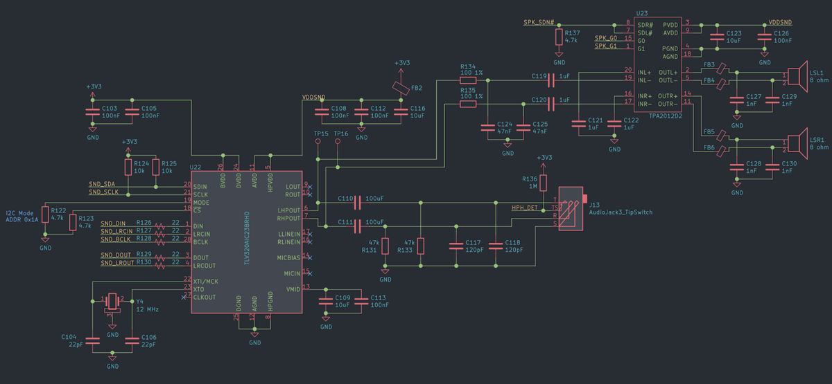
The following image is the schematic of Gameslab. The battery fuel gauge STC3115 is connected to the lower side of the battery (IBAT). At the time of writing the article, the following circuit diagram is before testing, 'Please do not imitate,' said Bishop. At the top of the schematic is a current sense amplifier for the main system rail, which is connected to all converters.
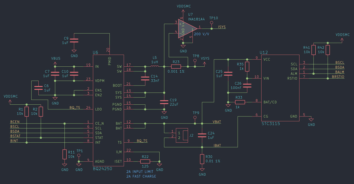
BQ24250 Rail Drives LDO to Power STM32L073 System Supervisor, Four Individual Switching Regulators for 1.0V / 1.5V / 1.8V / 3.3V Rails, LCD Backlight Driver, and 5V USB Boost Converter To do.
The
The Zynq FPGA subsystem includes a Zynq part with 512MB of DDR3 DRAM. DDR3 RAM operates at up to 533 MHz and provides up to 1066 Mbit / s throughput per data line. Here, 16 data lines are used for a total bandwidth of 2132 MB / s. Note that this is not the actual bandwidth, but a bandwidth that is about 80-90% efficient, optimized under all loads.
Zynq boots from the S25FL256S , a 32MB SPI flash. Zynq is also connected to the STM32L073 system monitoring program via I2C and UART, so U-boot and Linux consoles can be dumped from USB.
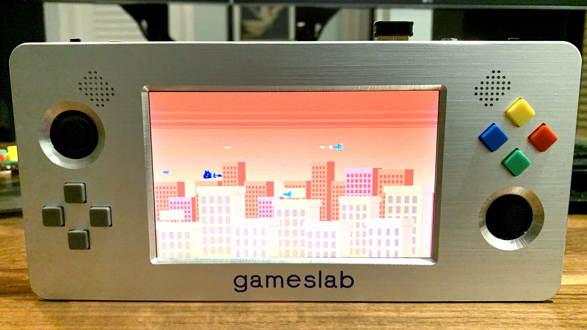
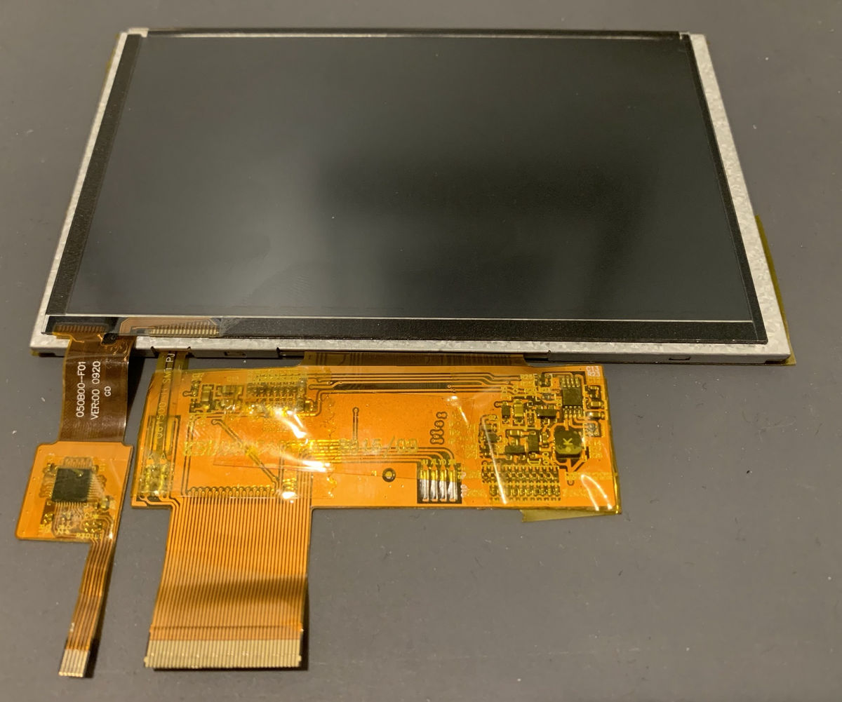
Gameslab's liquid crystal display (LCD) is a 5-inch (800 x 480) TFT LCD with a multi-touch panel mounted on top of it. The color is 8bit / channel RGB 24bit, vertical sync line, horizontal sync line. The LCD lines are driven directly from 3.3V LVCMOS FPGA I / O ports. The backlight has a complicated structure because it requires a driver that generates a high voltage to drive the entire LED. The multi-touch interface is connected to Zynq's ARM Cortex-A9 subsystem via an I2C connection.
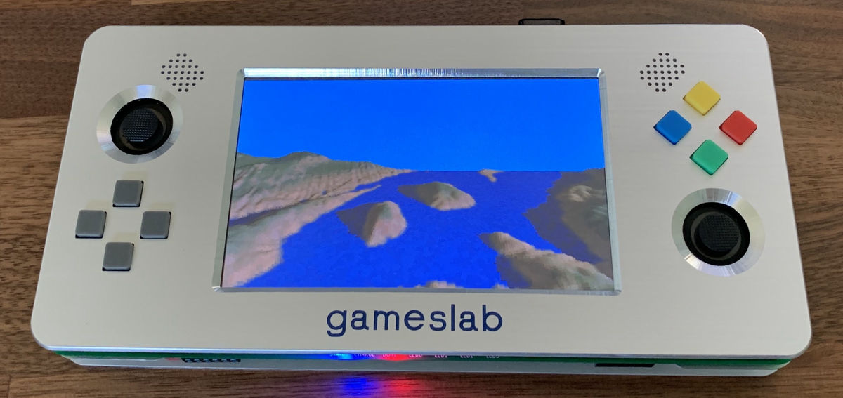
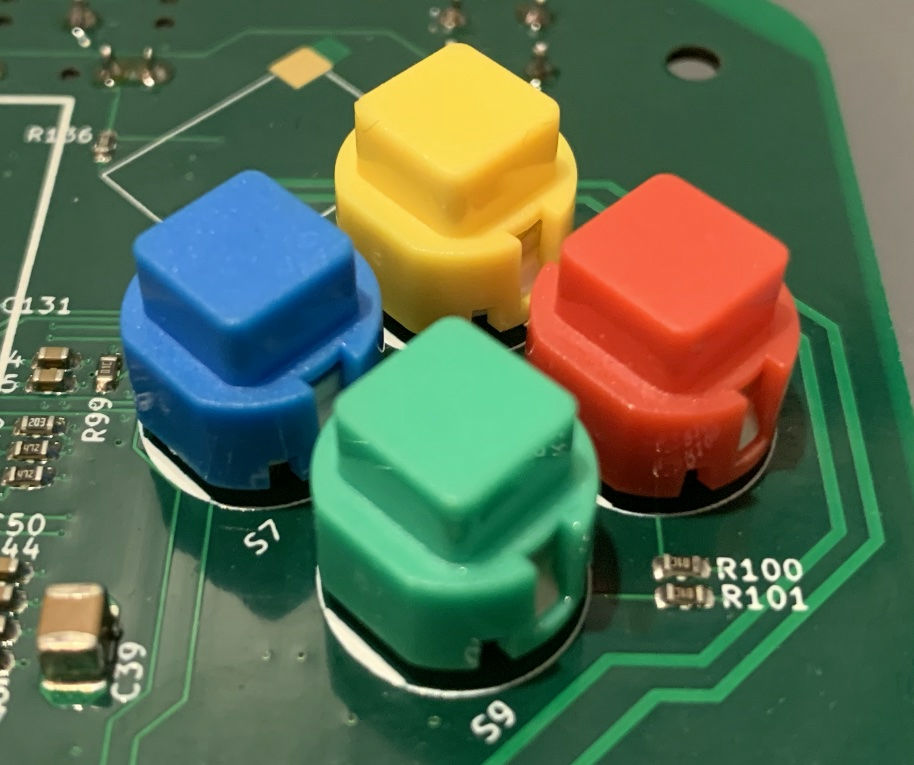
Gameslab has four colored buttons on the right, four gray directional buttons on the left, left and right shoulder buttons, and two sticks.
Gameslab's sound system includes a stereo codec with a built-in headphone amplifier and a Class D amplifier that drives two speakers. Before outputting to the codec via the I2S connection, flashy sound effects and mixing are performed on the FPGA side.
◆ Assembly of Gameslab
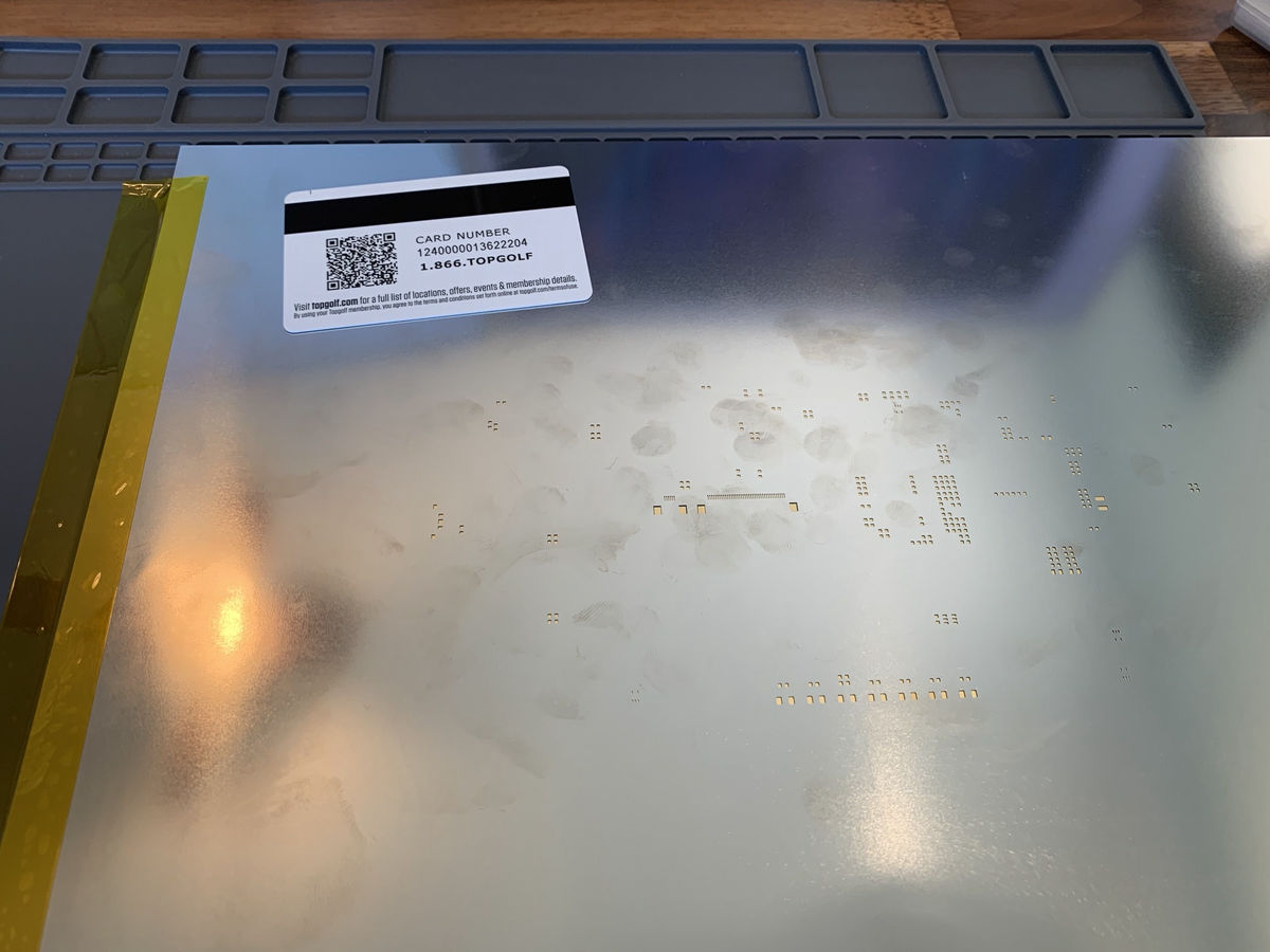
Bishop says designing Gameslab from a
A
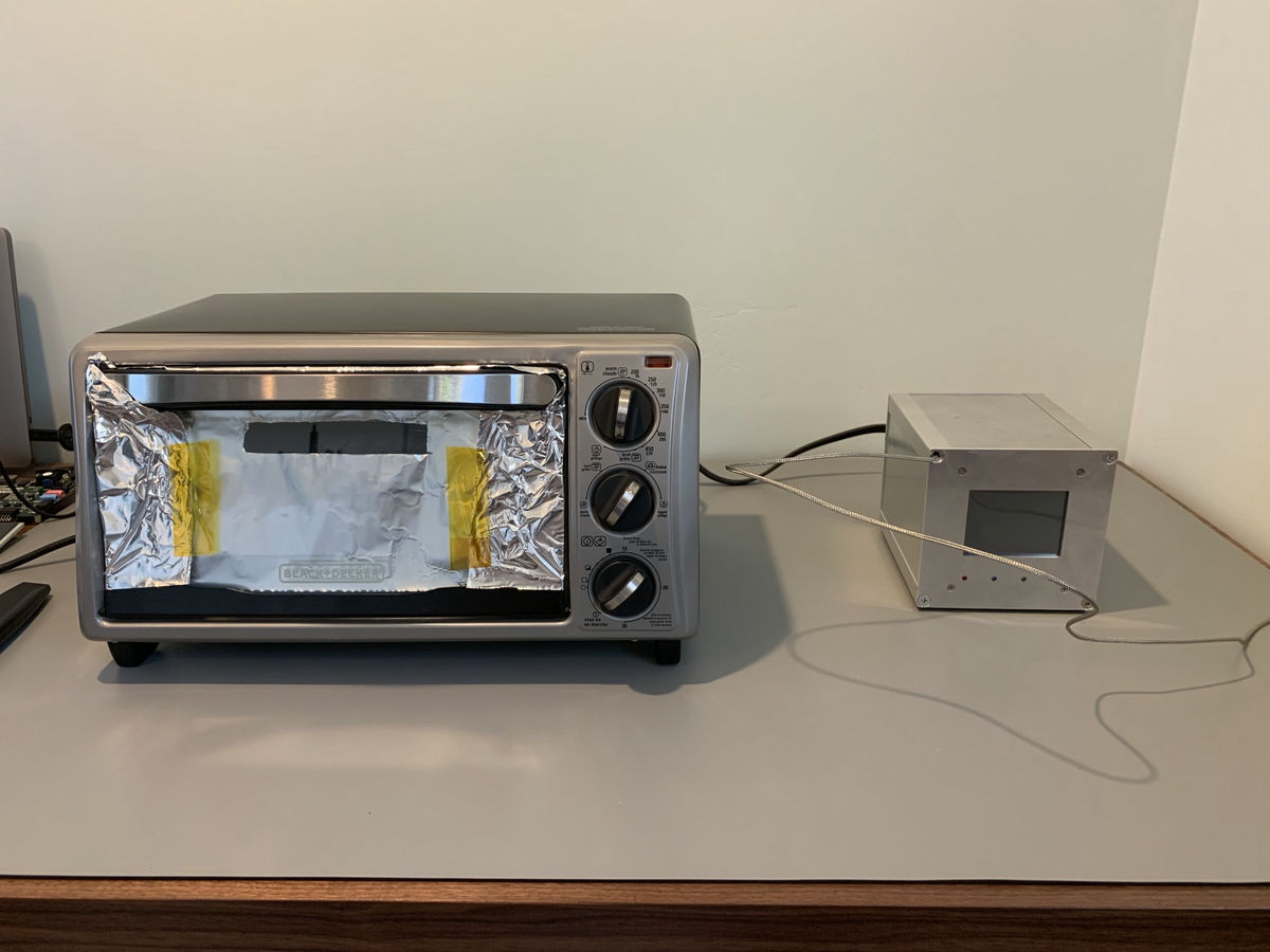
Bishop uses an oven toaster to reflow the solder after placing the components on the board. Since it is an oven toaster that can bake up to four breads at a time, it seems to be suitable for large printed circuit boards.
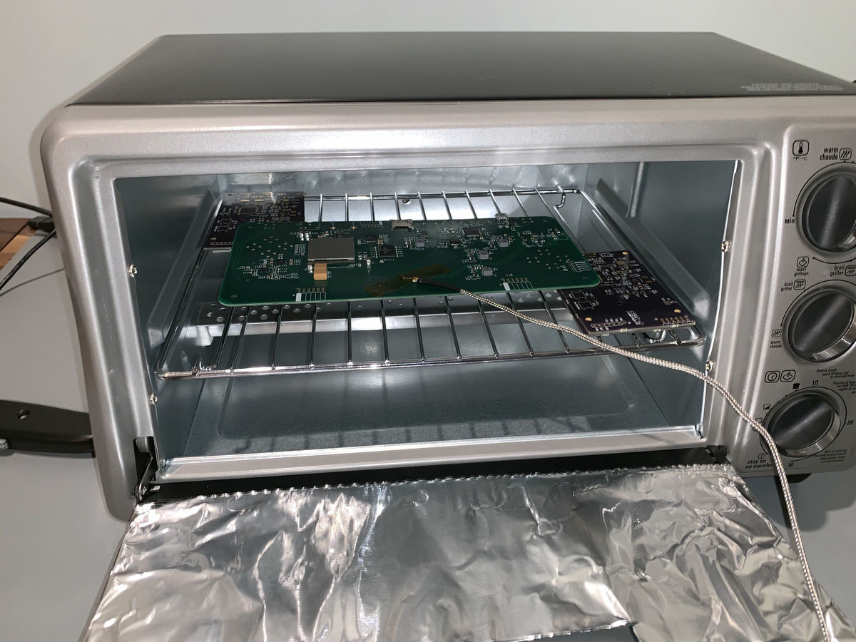
On the right is Bishop's own oven controller for reflow that monitors the oven with a thermocouple and turns the oven on and off with PID control. According to the reflow process in the oven toaster, although some bridges occurred in the 0.5mm pitch LCD connector, they all worked without problems.
Then
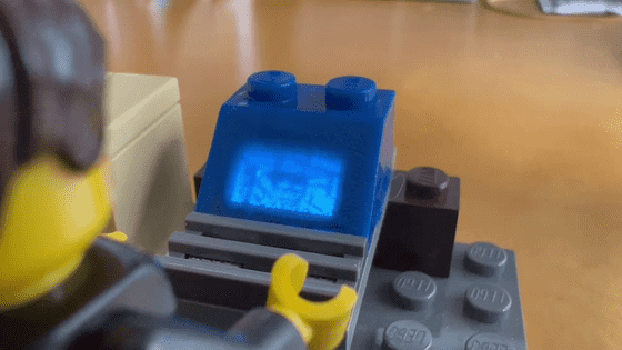
You can check the contents of Gameslab from the following movie.
Gameslab case in detail-YouTube
Related Posts: