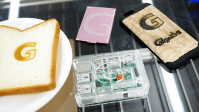
I tried assembling and using "Smart Laser CO 2" which realized the home laser cutter at business level output & 1/10 price
A laser cutter (laser processing machine) "that makes it possible for a maker who creates anything to cut precisely, is a popular equipment that makes it two-perfect with a 3D printer. Among them, high outputCO 2 laser(CO 2 laser) processing machine is very useful because it can cut even thick acrylic, but there are many things with several million yen price, it was a substitute that can not be handed out. However, based in Yamanashi PrefectureSmartDIYs, CO2 laser processing machine with output 40 W "Smart Laser CO 2"I released the DIY kit at a low price of 248,800 yen. I tried the power of the CO2 laser actually assembled to see what kind of laser processing machine "Smart Laser CO 2" of Made in Japan caused the cost destruction of the high power laser processing machine.
World's largest assembled CO 2 laser processing machine (cutter) Smart Laser CO 2
http://www.smartdiys.com/smart-laser-co2/
You can see what kind of processing can be done with Smart Laser CO2 with the following movie.
I tried putting brown on Lauan plywood at the world's largest assembled CO 2 laser processing machine "Smart Laser CO 2" - YouTube
◆ Assembling the laser processing machine
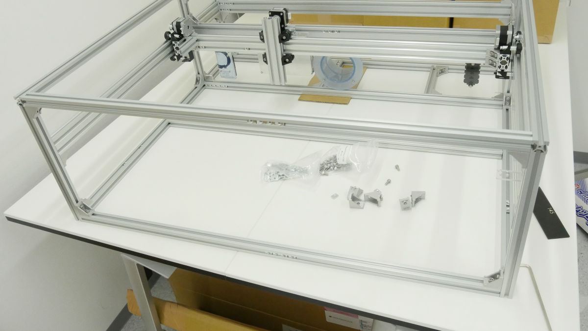
A set of "Smart Laser CO 2" assembly kit arrived at GIGAZINE Editorial Department. The total number of packages is 9, which implies at this point the ruggedness of the way to completion.
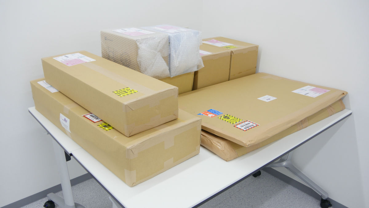
Tentatively check inside the box.

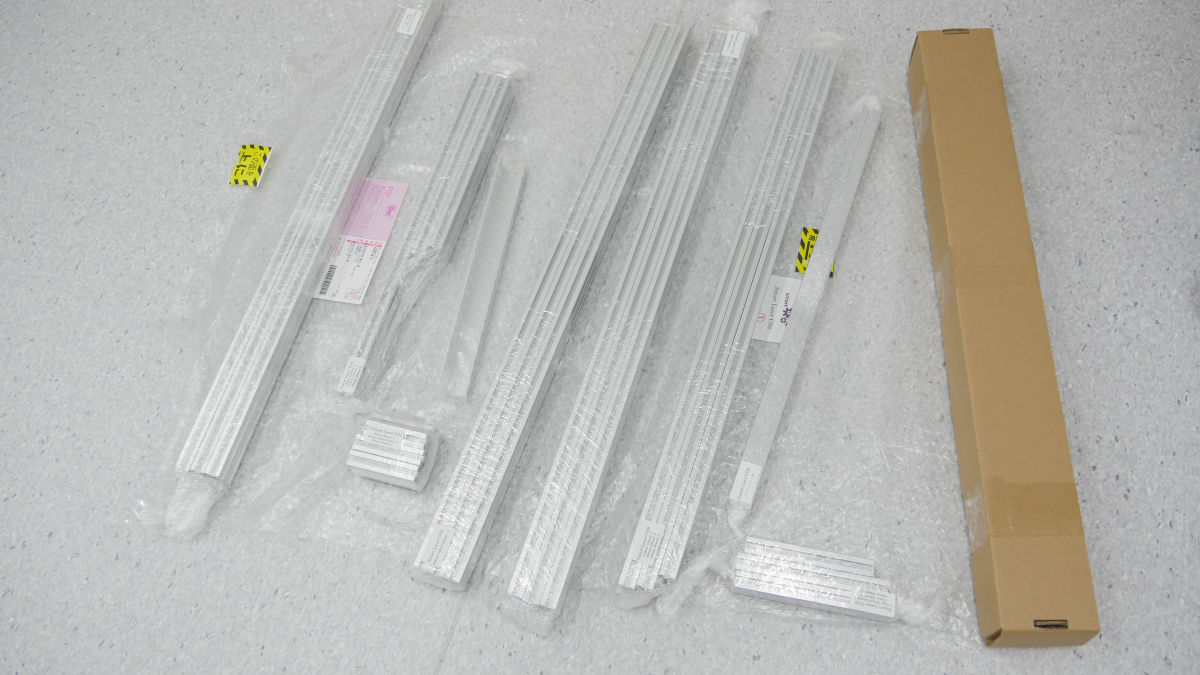
Aluminum parts for frame ......
Water cooling kit such as hose, radiator and fan ......

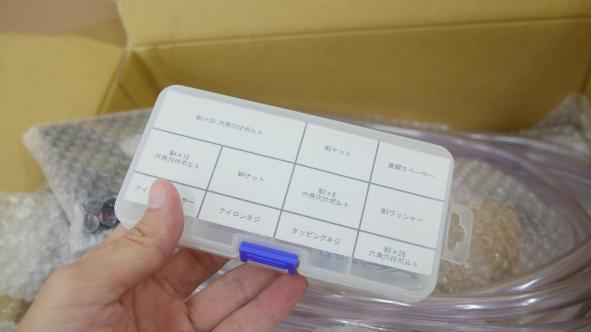
Case including a set of screws etc. Even with confirmation work of accessories, considerable time and enormous space are necessary.
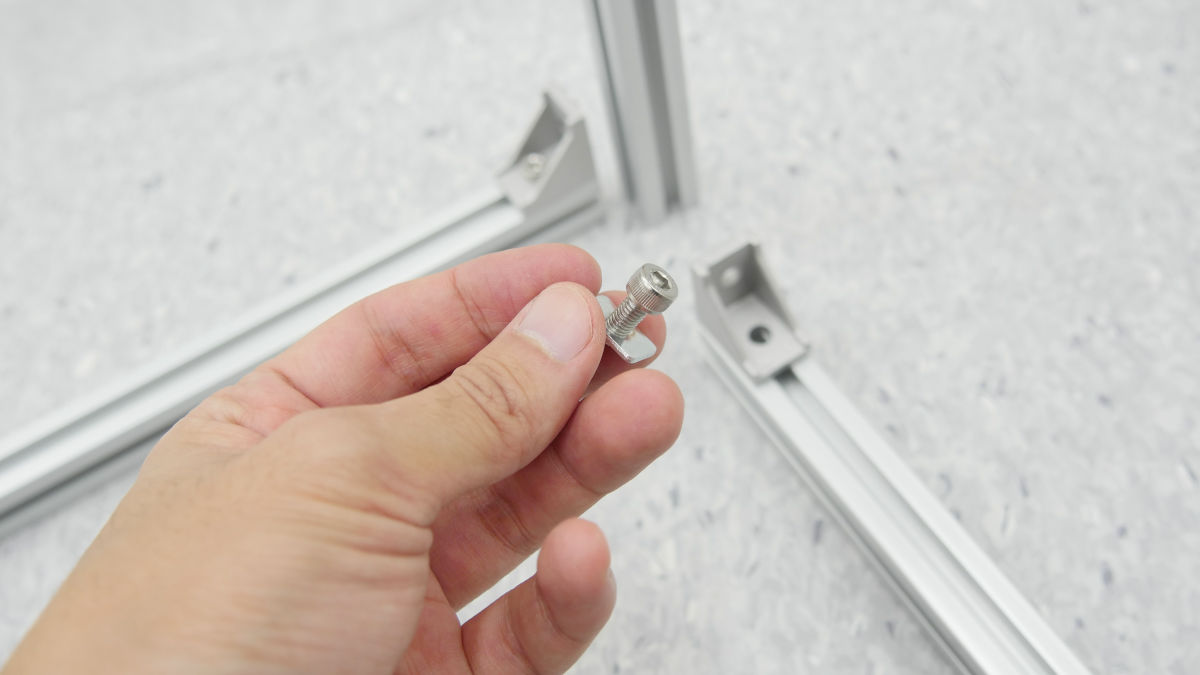
· Frame assembly
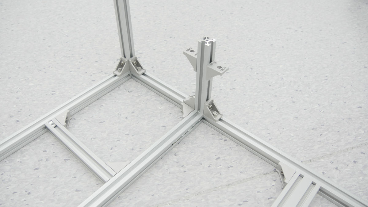
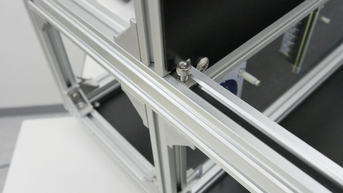
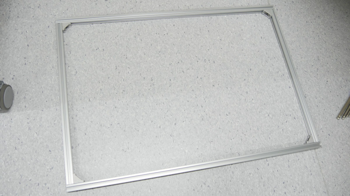
That's why I started assembly. First from the frame making. Attach the aluminum frame with right angle bracket and M5 bolt + T nut.
While careful not to make it as perpendicular as possible, I will battle hard.
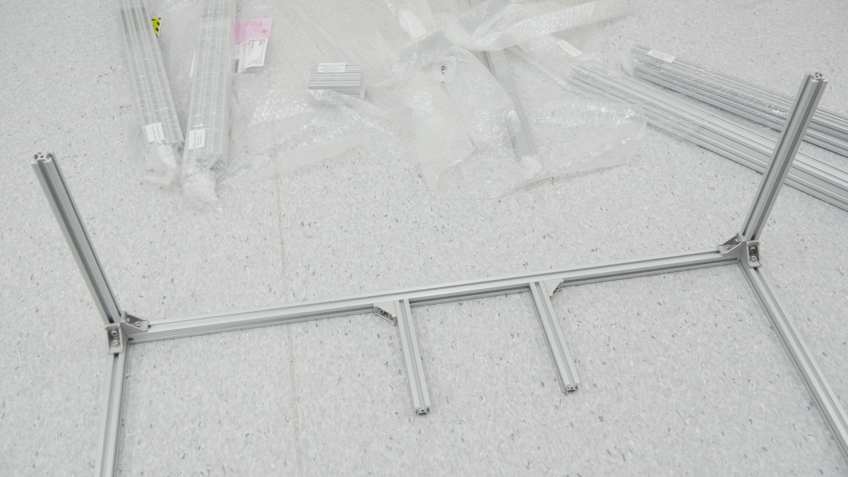
While deciding key points and positions with the attached acrylic parts ......
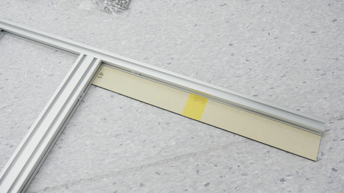
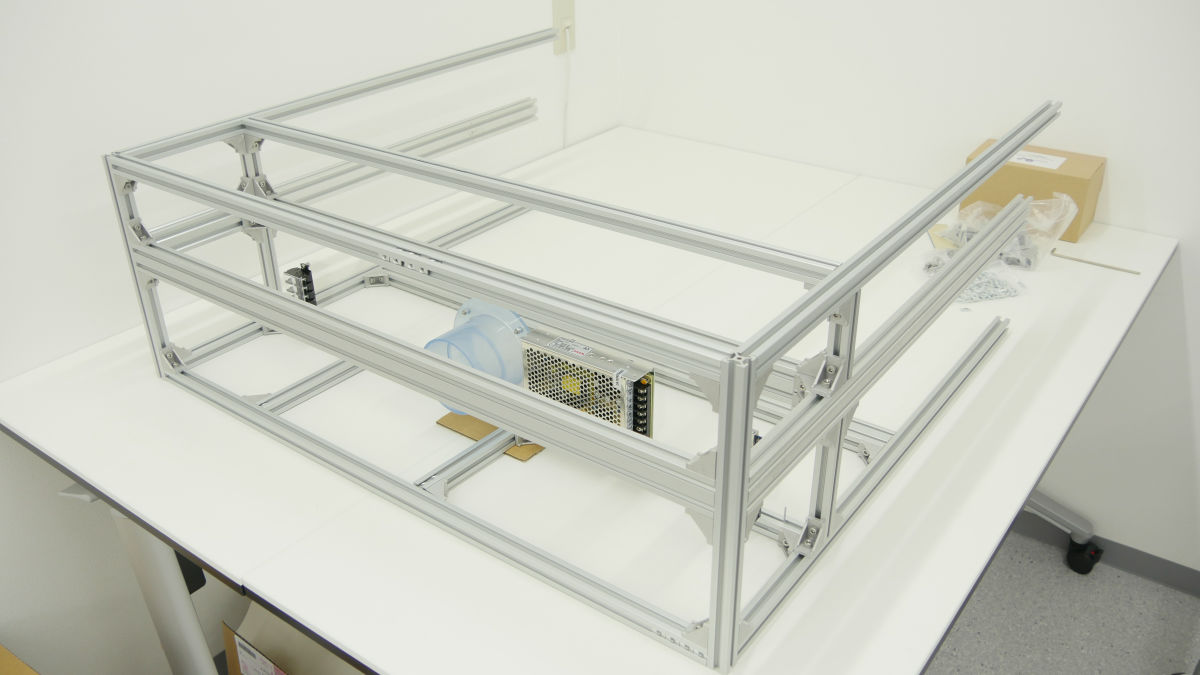
The bottom frame is completed. It is two hours strong so far. It is hard to find the necessary parts from the mountain of parts, so it takes more time than you can imagine.
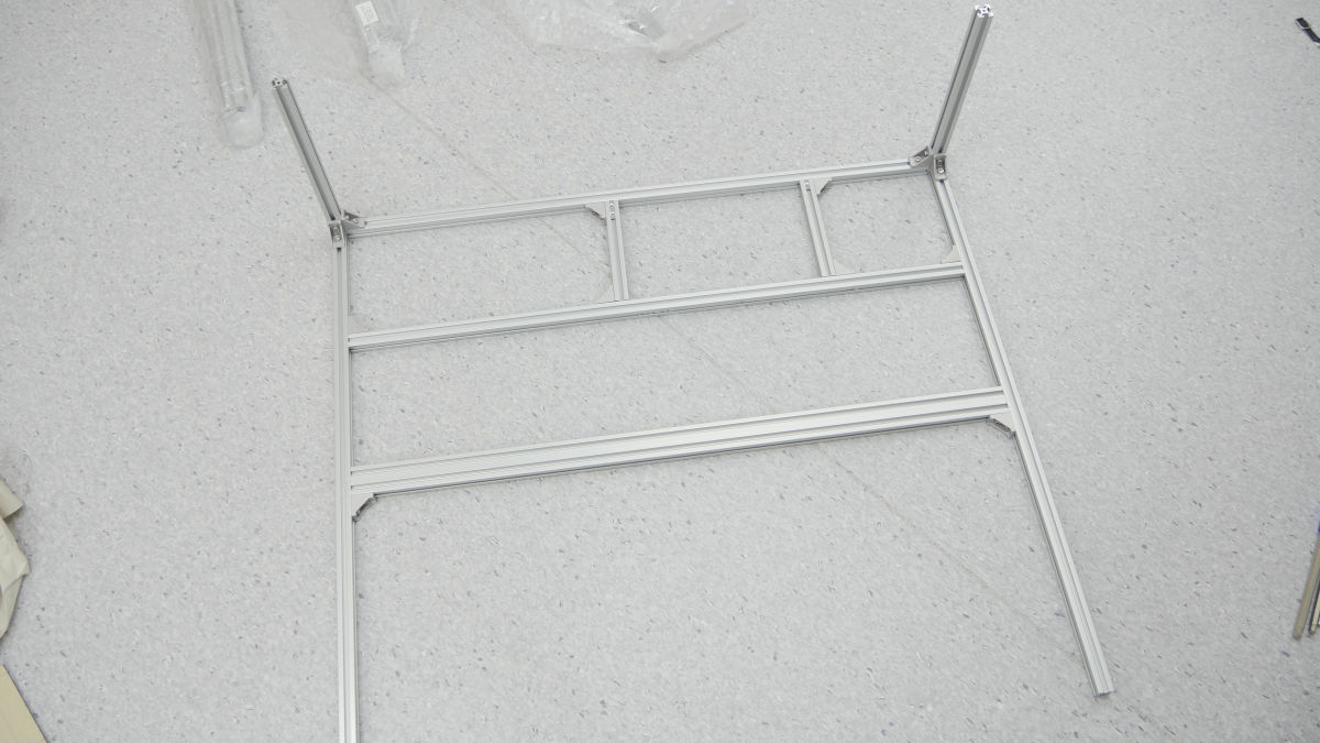
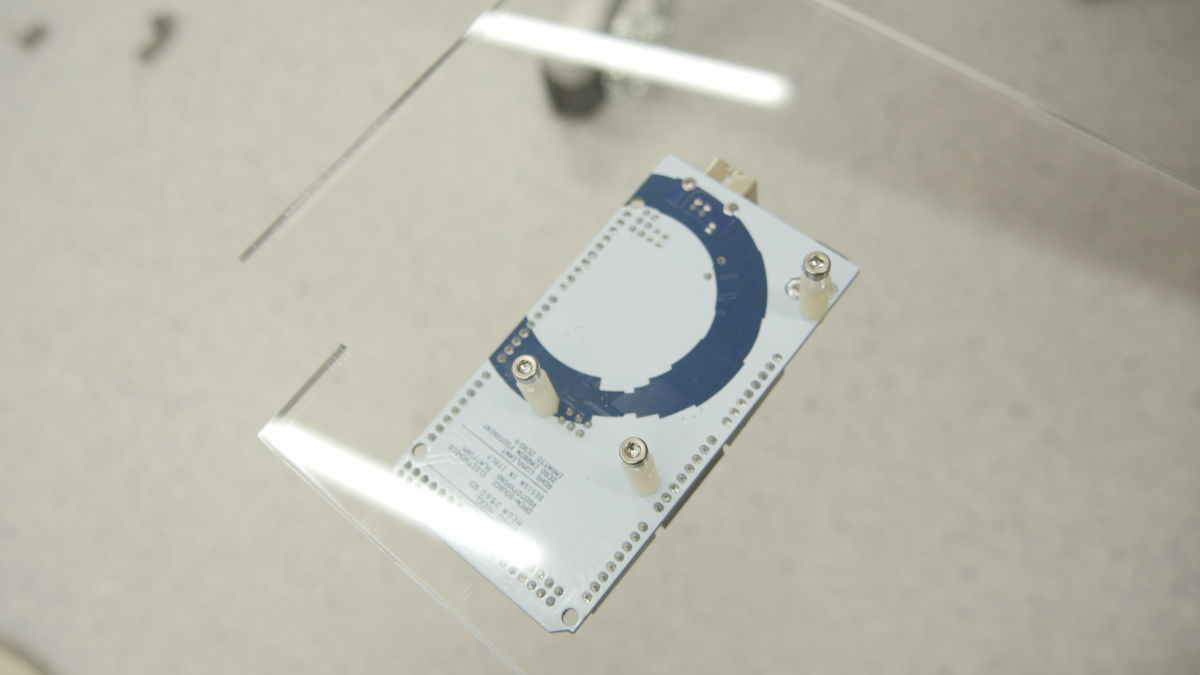
· Inner panel
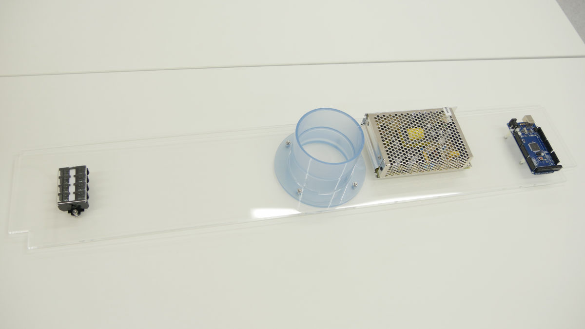
The brains of Smart Laser CO2 are the microcontroller board Arduino Mega.
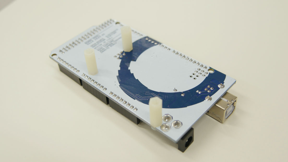
Attach to acrylic panel with nylon spacer.
This is a switching power supply.
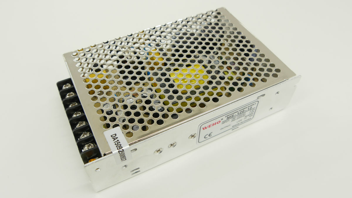
Also attached to acrylic panel.
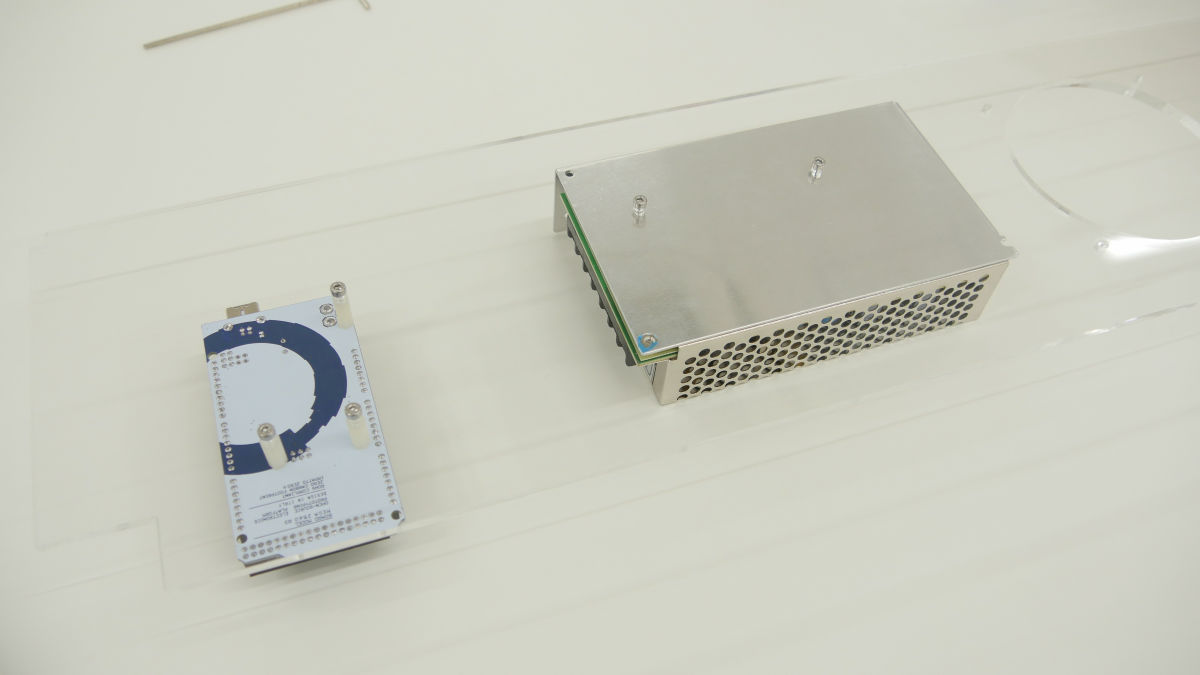
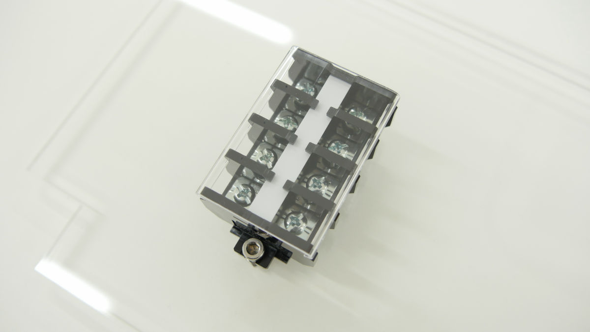
With a plastic socket ......
Terminal is also set.
The inner acrylic panel is finished.
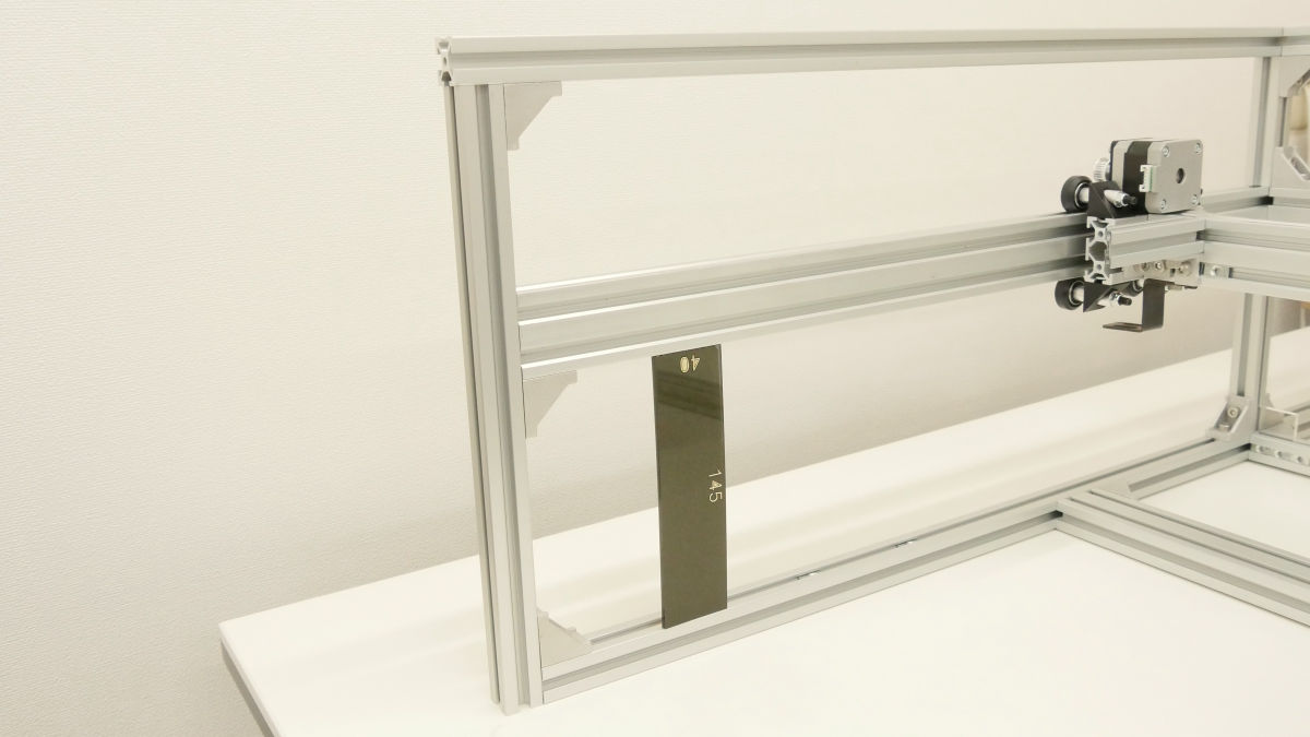
Attach 145 mm aluminum frame and right angle bracket to the frame ... ....
Attach the acrylic panel.
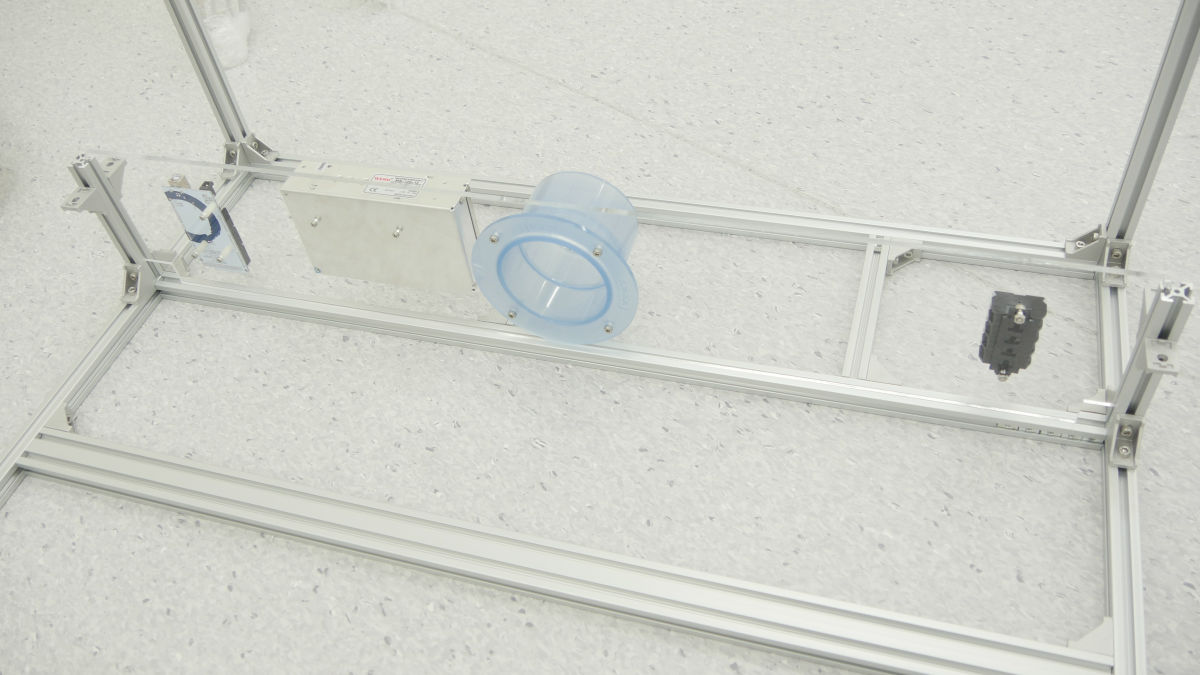
We will build up the middle and upper stages of the aluminum frame.
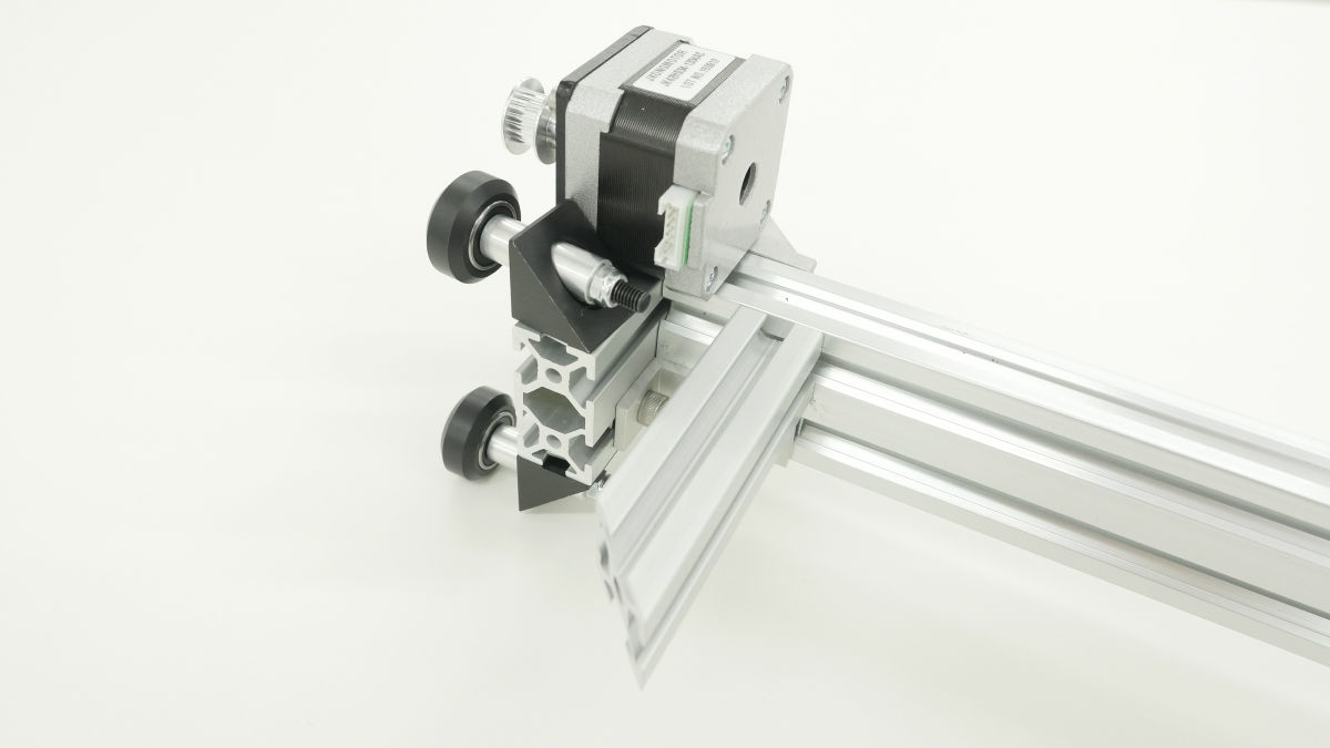
· Shaft unit
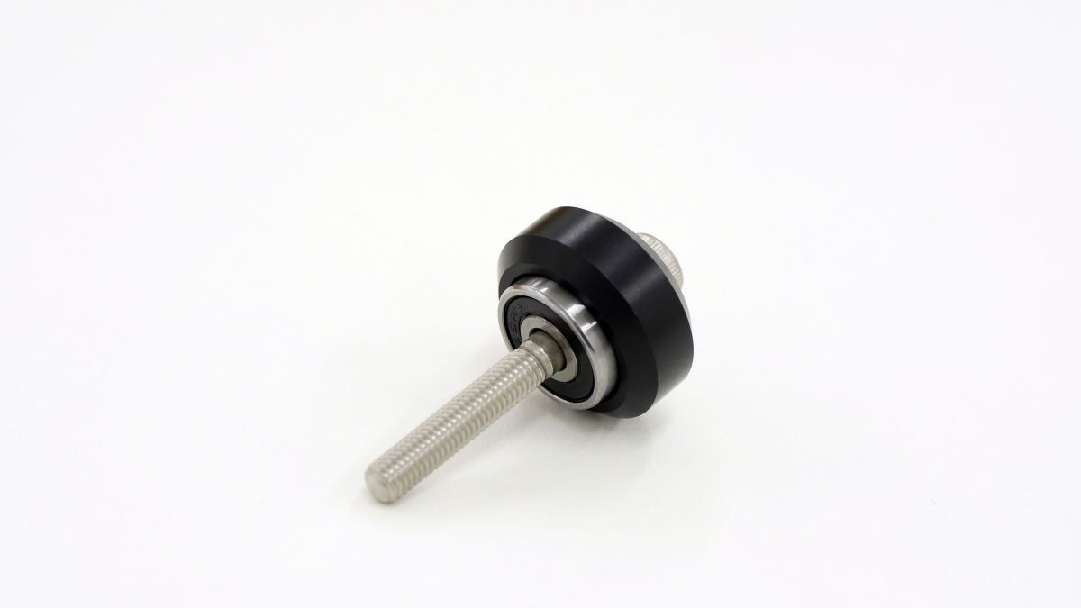
Wheel and bearing of moving part of X axis unit (solid v wheel unit).
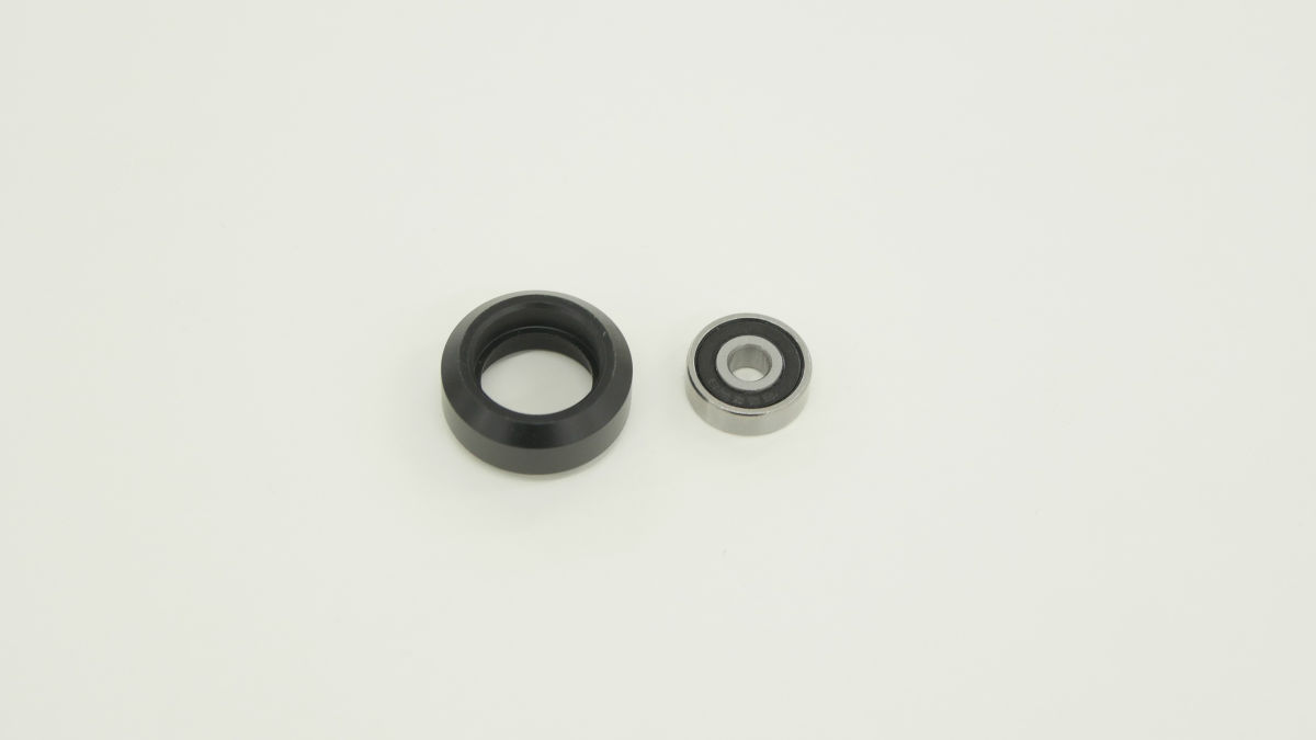
Fit the bearing in the wheel ......
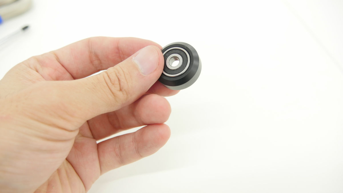
Insert the bolt with M5 × 40 hexagon socket and place the shim in between ... ...
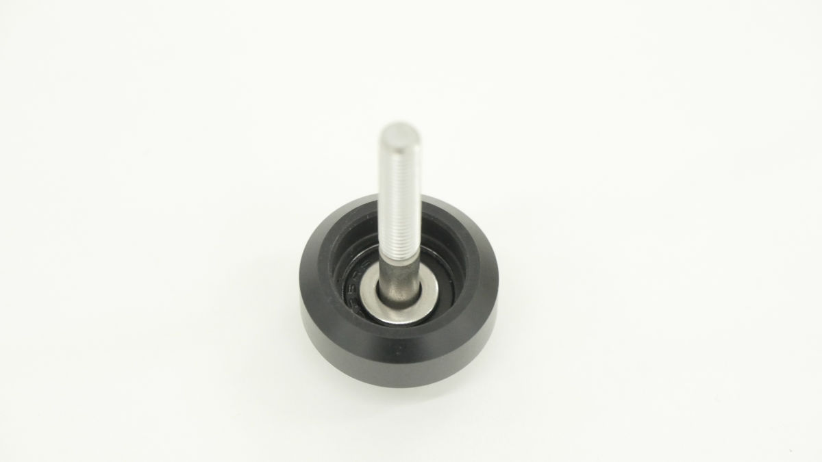
If you install a bearing so as to sandwich it is ok.
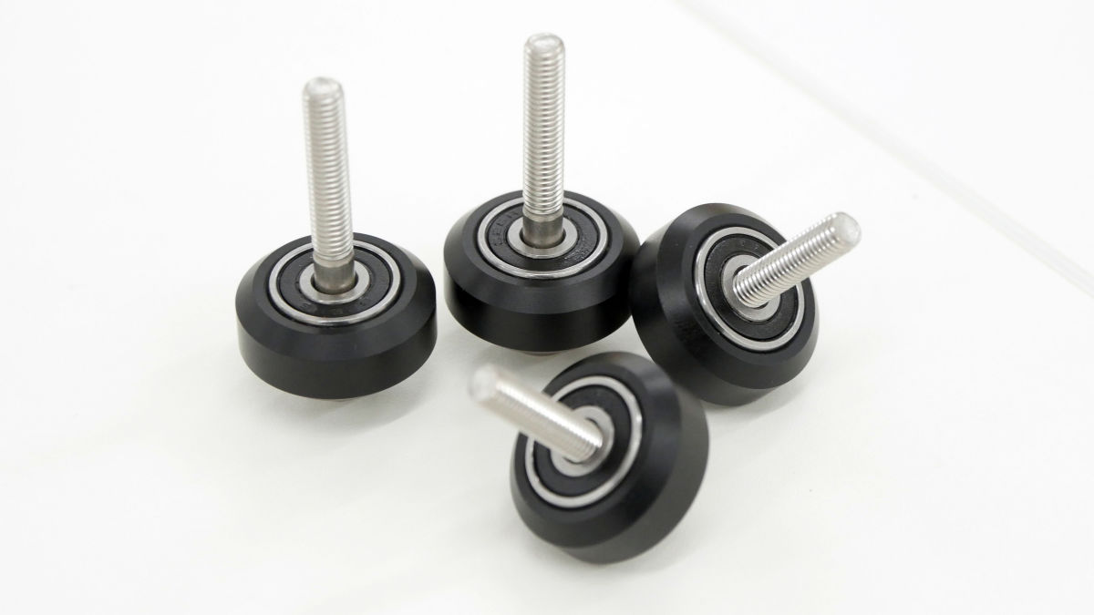
We assemble four pieces in the same way.
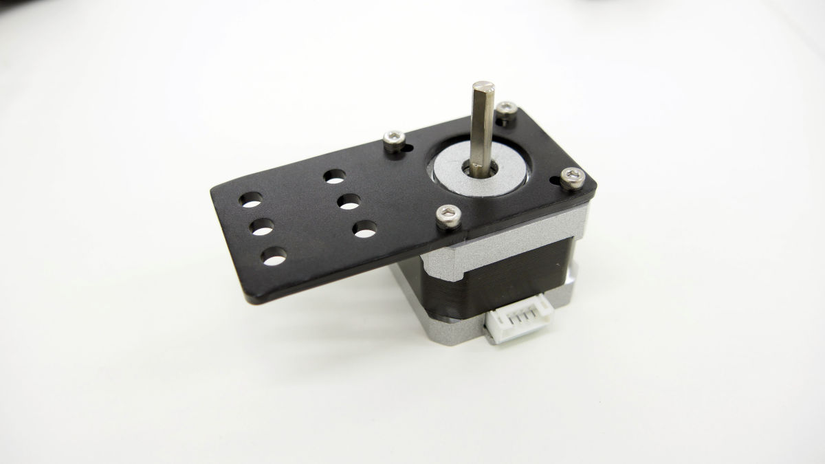
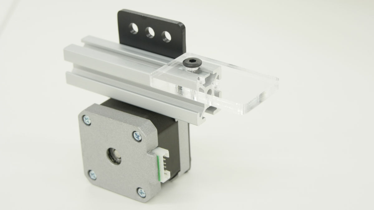
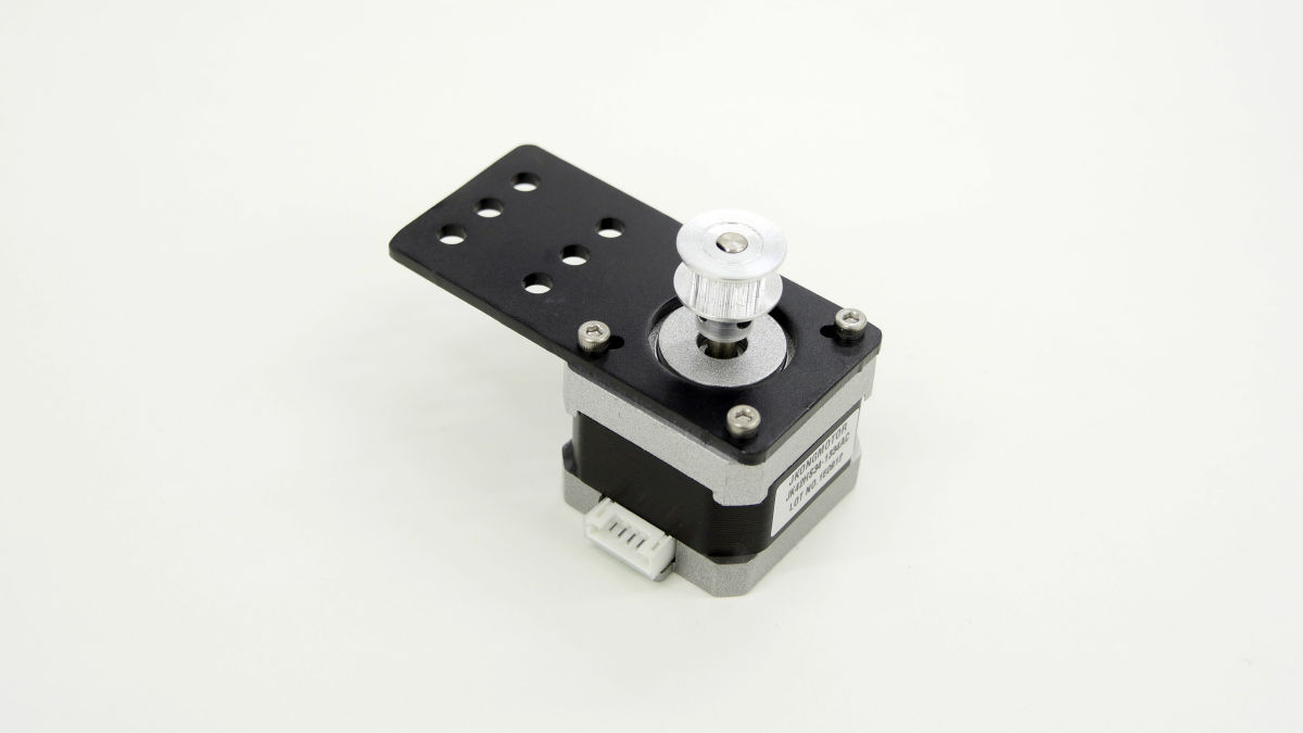
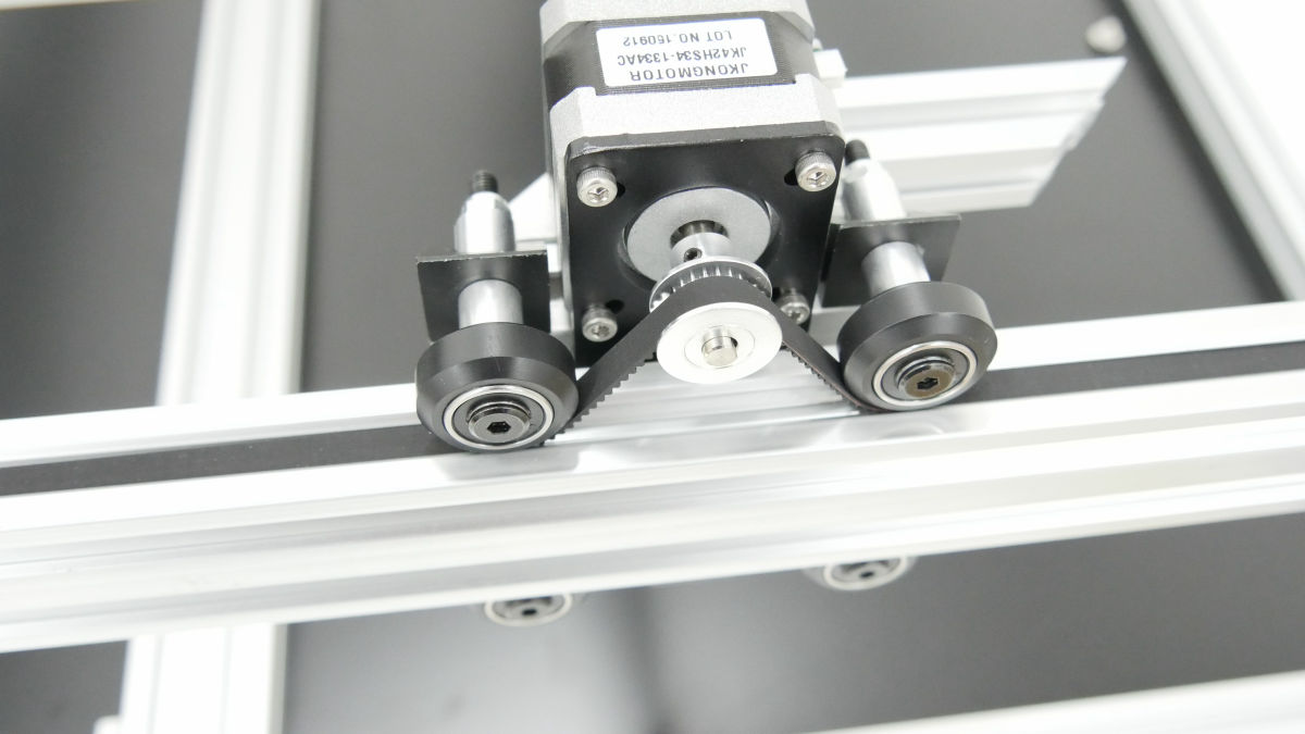
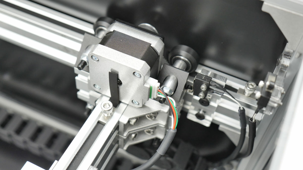
Stepping motor and mounting panel.

I installed it like this.
Attach the timing pulley to the motor ......
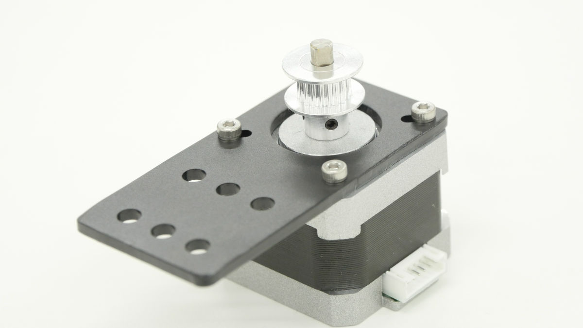
Attach 80 mm aluminum frame.

Care must be taken so that the stepping motor does not come into contact with the aluminum frame.

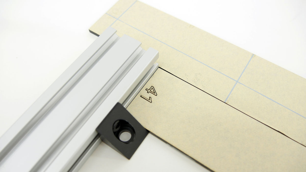
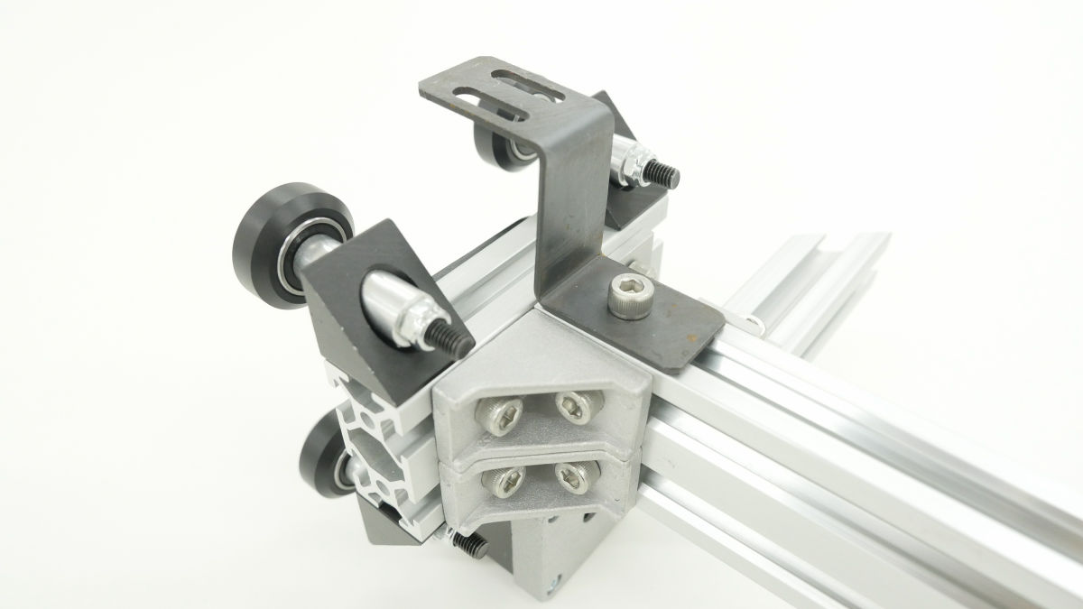
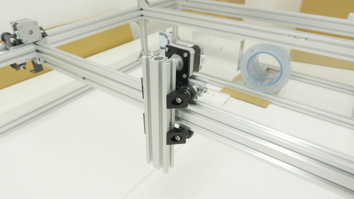
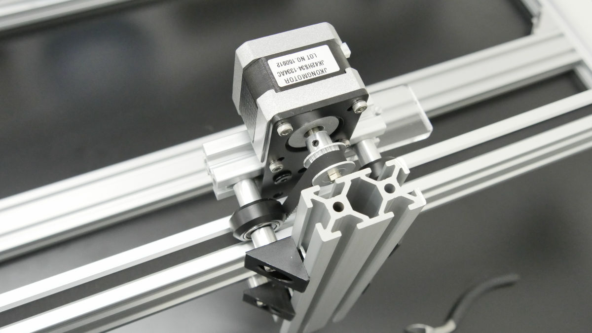
Using 41 mm acrylic, attach the angle connector to the aluminum frame.
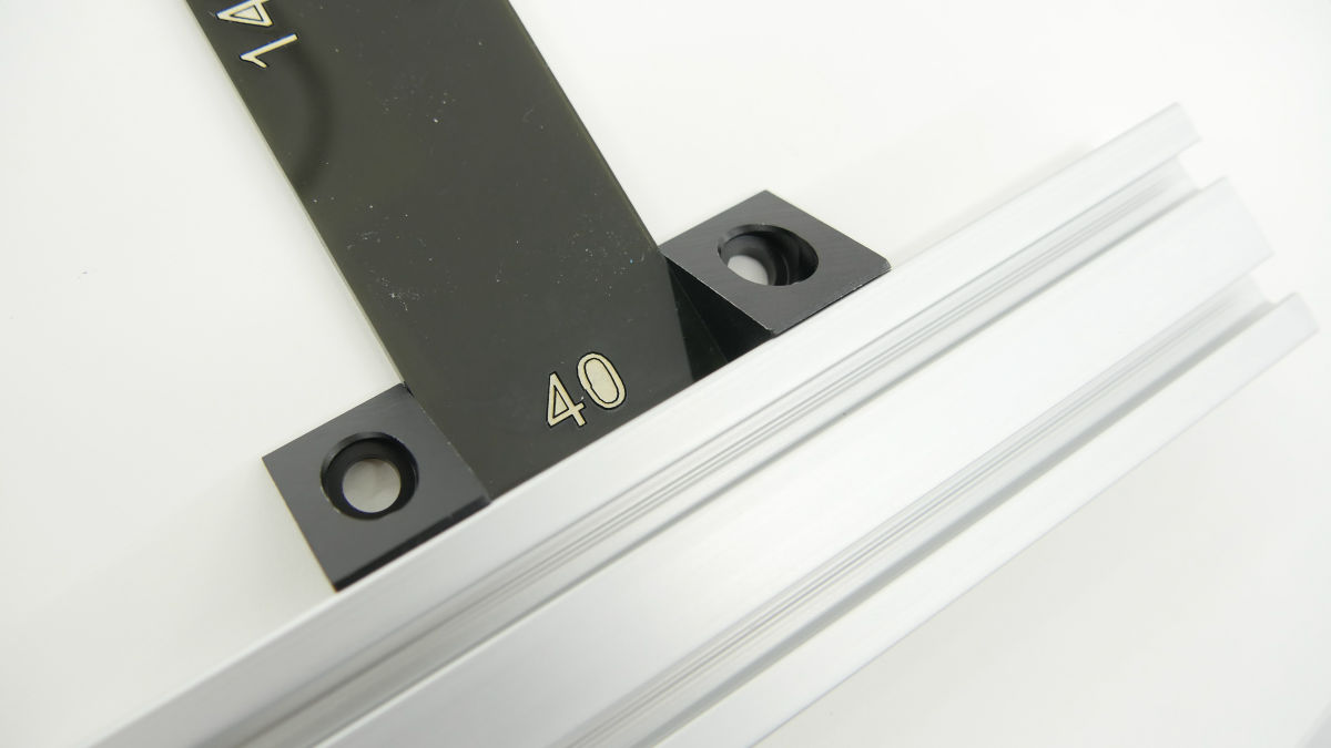
Then decide the position precisely with 40 mm acrylic, then attach the second angle connector.
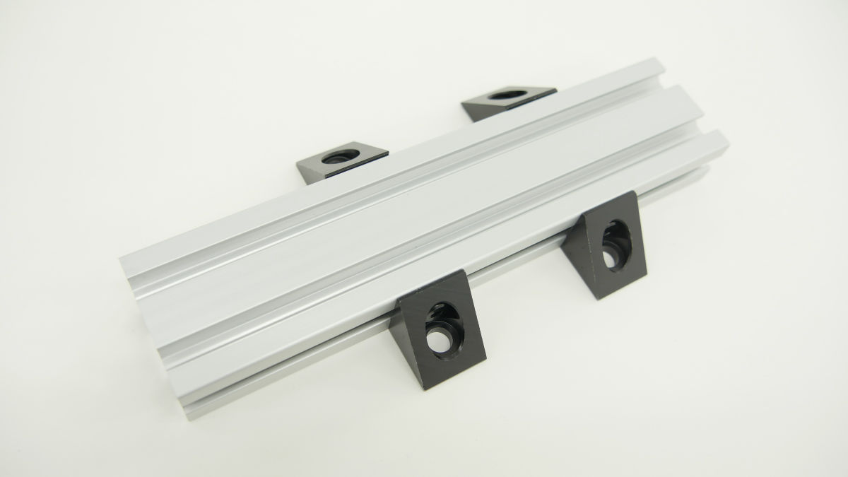
Also installed on the other side.
Finally, installing carrier support (X axis) acrylic, the X axis motor frame unit is completed.
Like the X axis, create 8 solid v wheel units of Y axis with wheel + bearing.

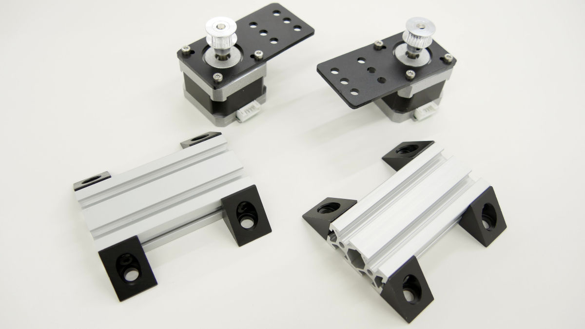
Attach the mounting plate to the stepping motor.
Make Y axis frame unit by attaching angle connector to both sides of 85 mm aluminum frame.

We will make 2 sets.
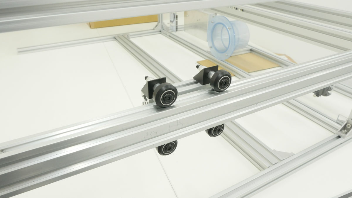
Insert a spacer in the angle connector and insert a solid v wheel unit.

With this feeling it is checked whether the side frame is smoothly moved through the Y axis unit without rattling.
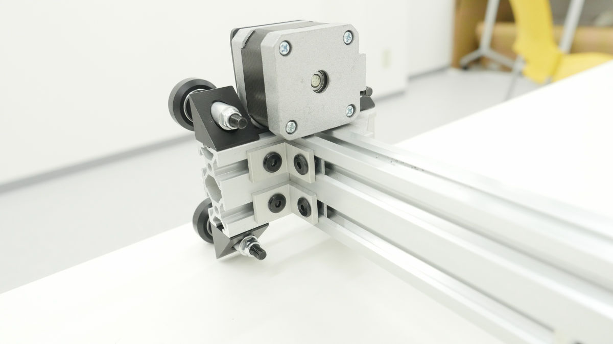
After checking, install the motor unit.

Next, the motor unit is mounted on both sides of the 805 mm aluminum frame.

Aluminum frame for the second mirror ...
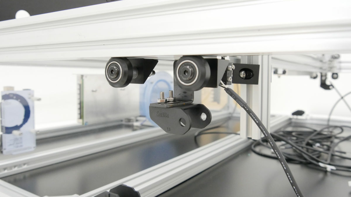
Completion of the shaft unit by mounting the carrier mount.
I will incorporate it into frames on both sides like this.
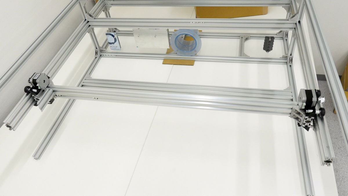
Attach the motor unit to the X axis unit ......
Mount on the X axis frame and check for tilt and rattling. This completes the shaft unit part.
145 × 40 Acrylic is sandwiched and adjusted while attaching the frame end part.
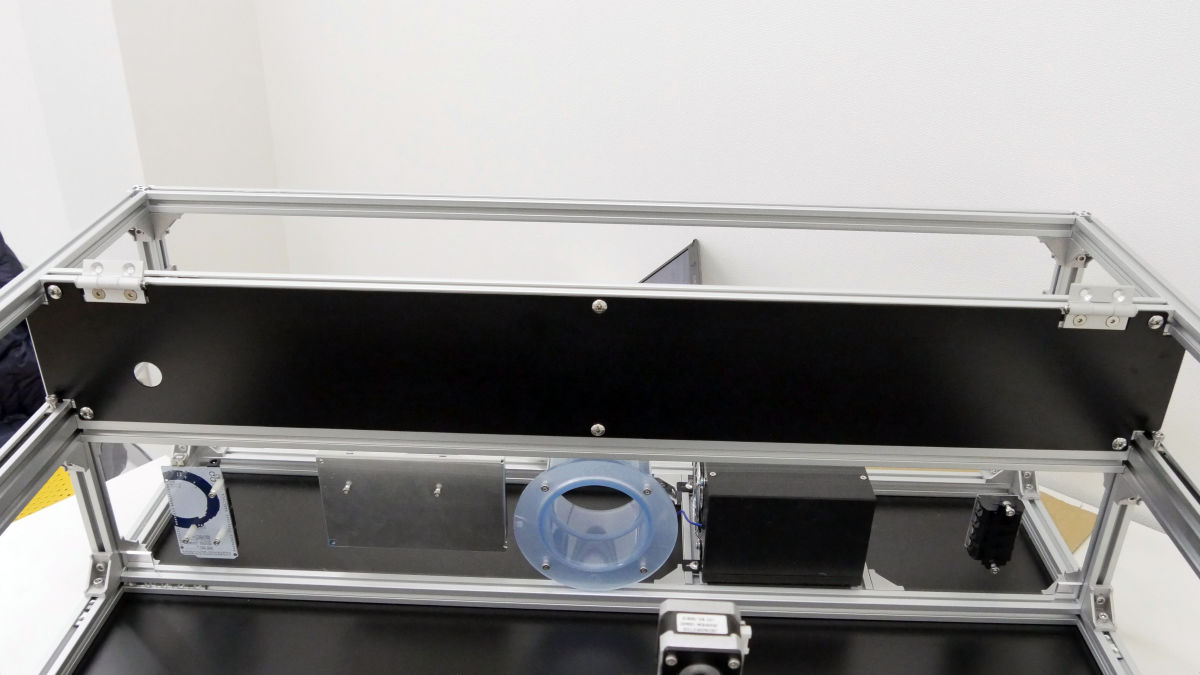
This completes the frame.
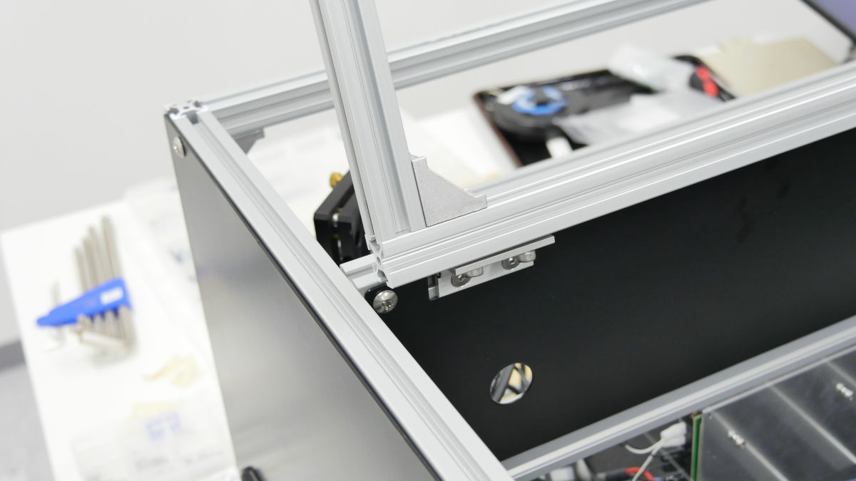
Tilt the frame which has become the size and the weight which is already difficult to move alone by 90 degrees, and attach the cover bottom and the rubber feet.
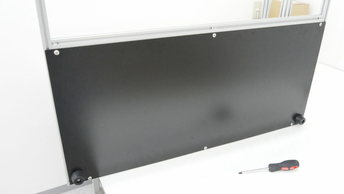
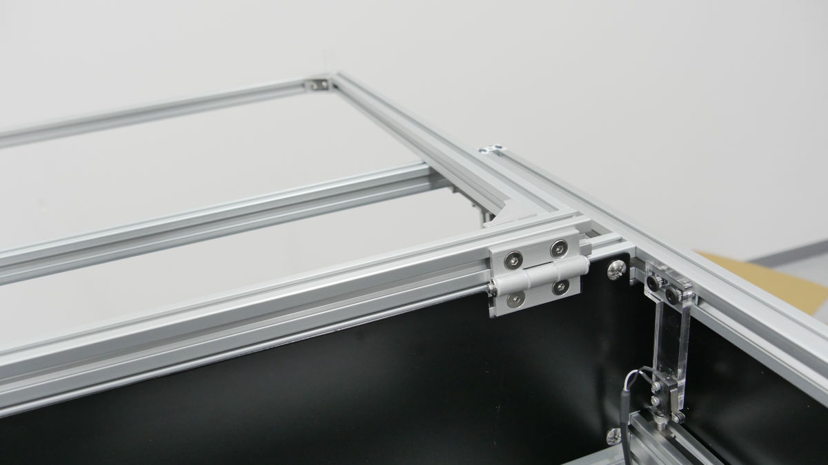
The inner cover is also attached with a hinge.
Insert the timing belt into the groove of the V slot, place the M5 post-fitting nut on it, and fix with the M5 × 10 hexagon socket head bolt.
Pass the timing belt through the Y axis unit.
Also insert a timing belt on the X axis.
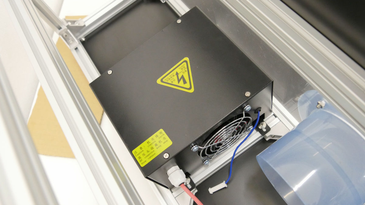
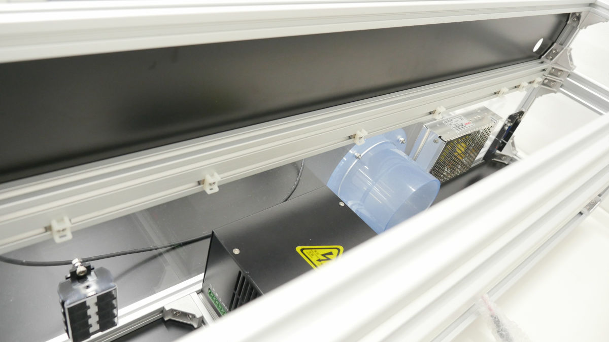
Next, install the laser power supply at the lower rear part of the laser processing machine.
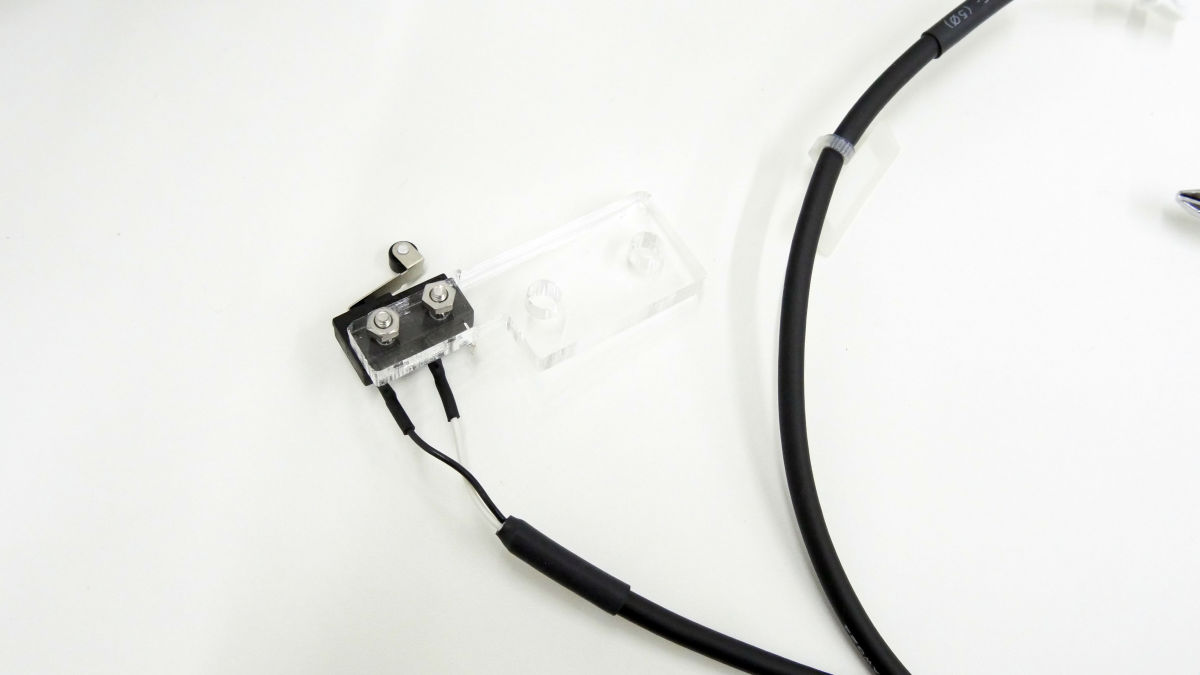
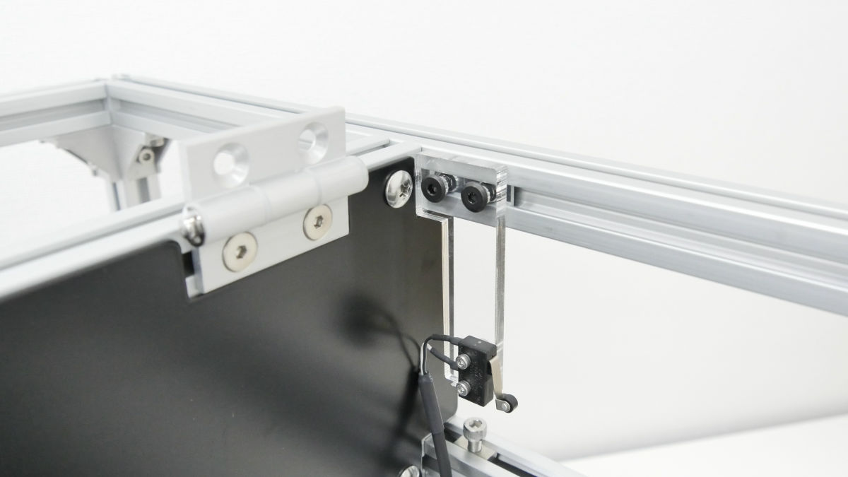
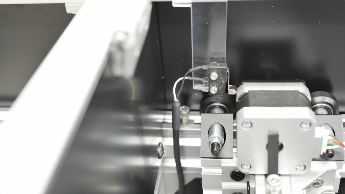
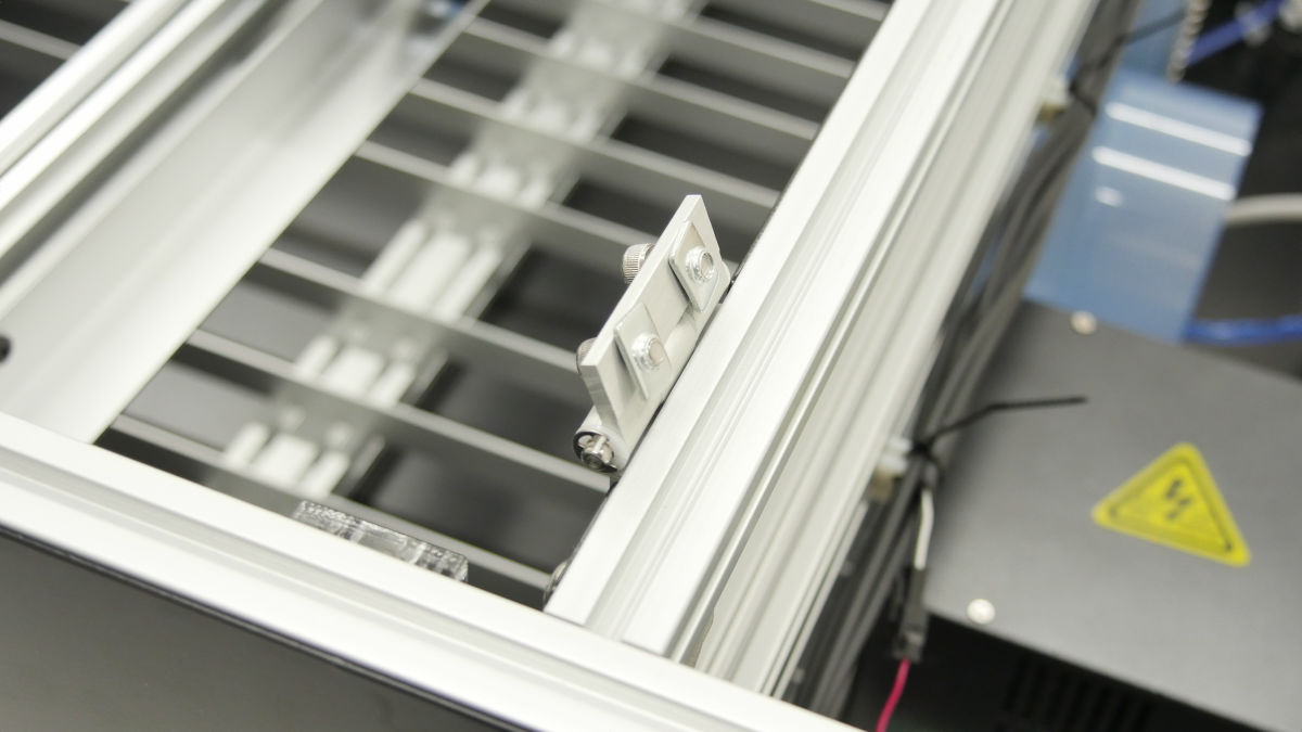
·limit
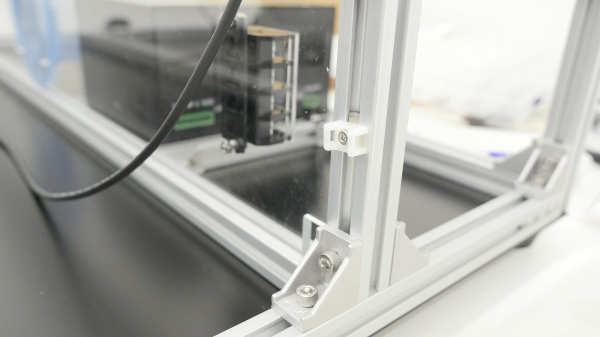
Next, attach a limit (end point) to the X and Y axes. Each limit is equipped with a cable limit end on acrylic.
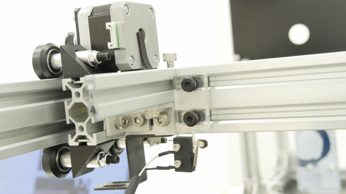
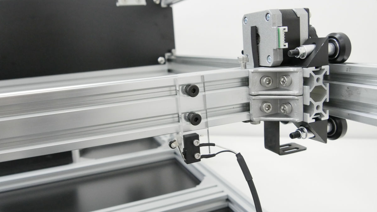
Attach the limit to the specified place on the X axis and Y axis.

·wiring
Attach the L-shaped aluminum flat bar to the X axis and attach the cable carrier mounting bracket.
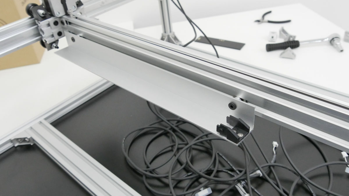
Cable carrier mounting bracket on the X axis ......
Below the body frame
It is also attached to the Y axis.
Front cover attached ......

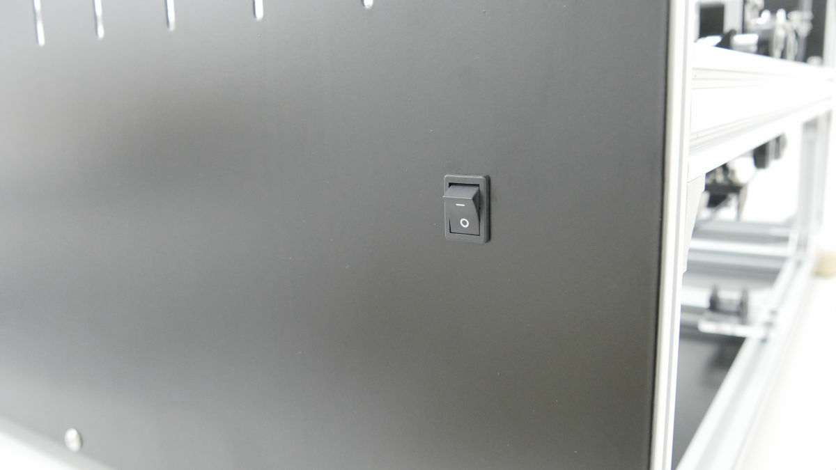
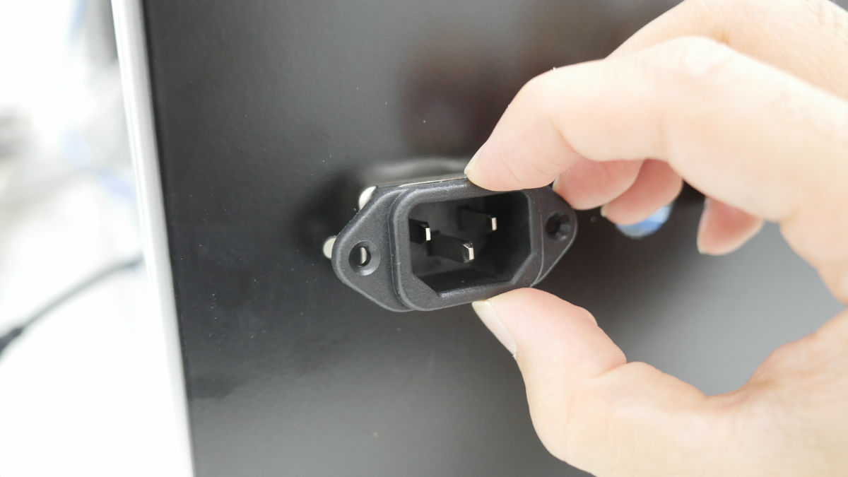
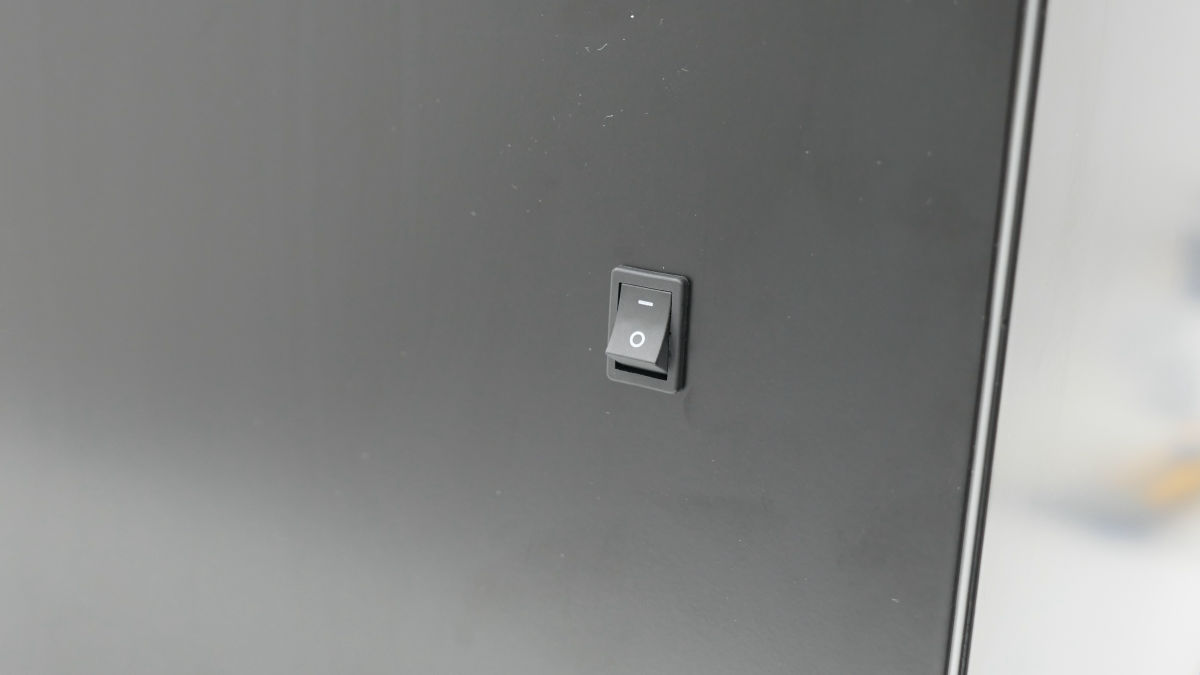
AC switch is also installed.
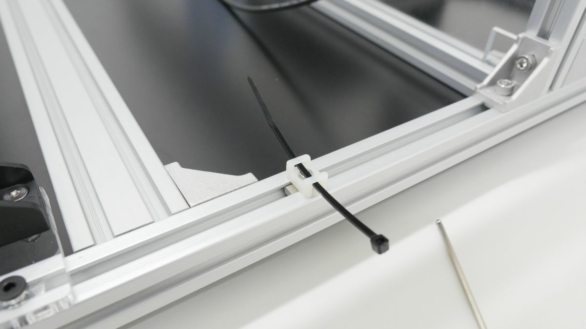
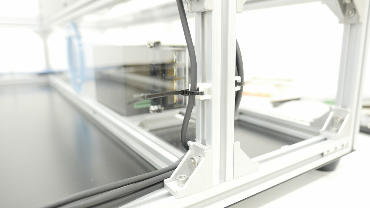
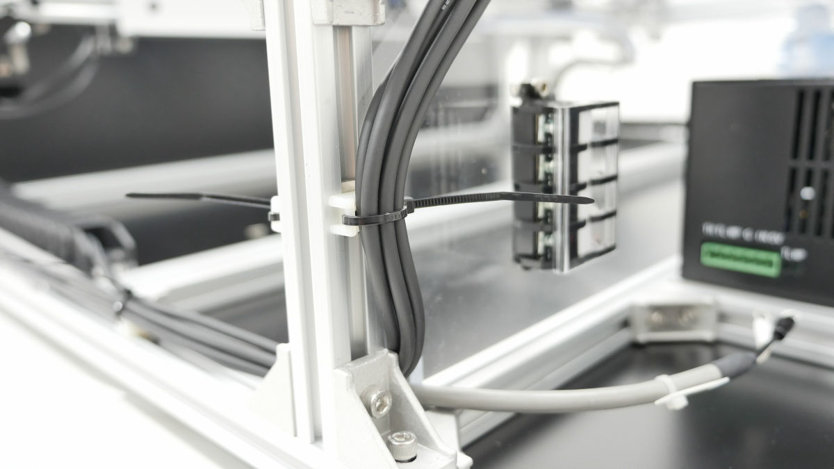
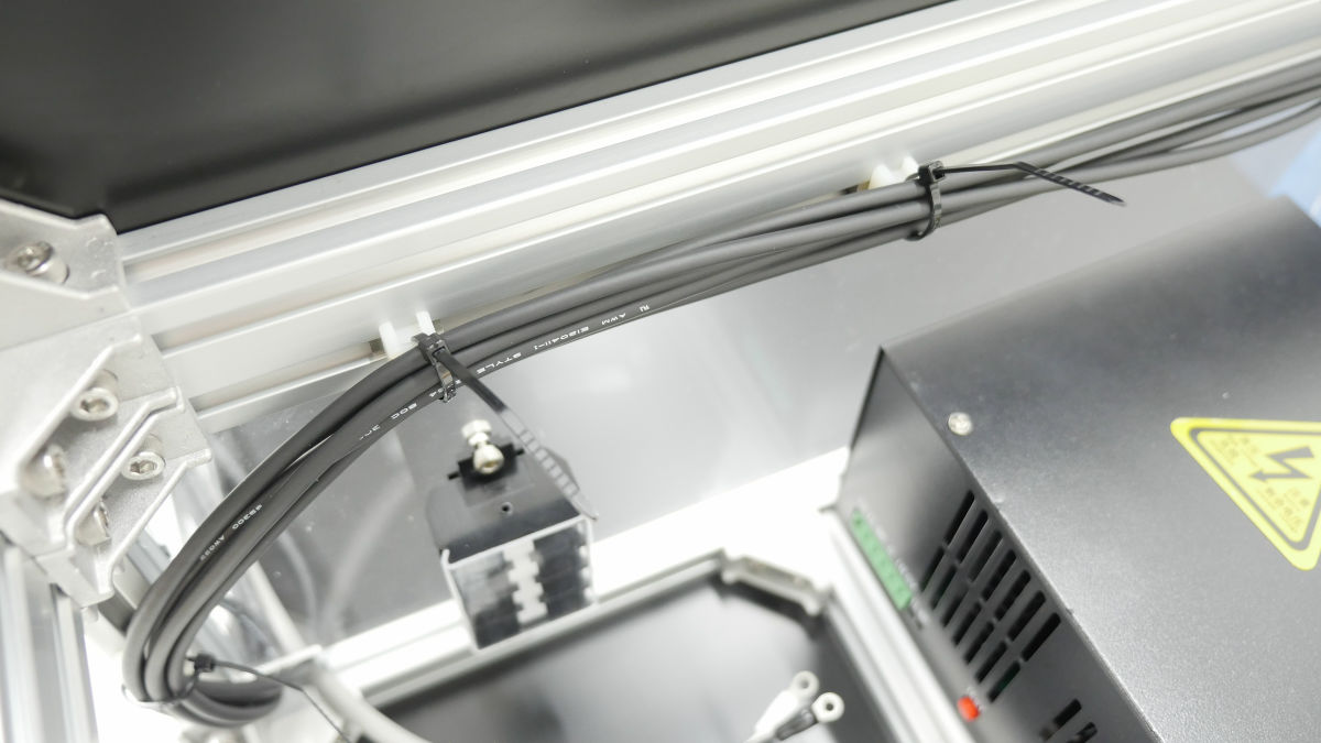
Attach fasteners to various parts of the frame to pass the pre-installed binding band.
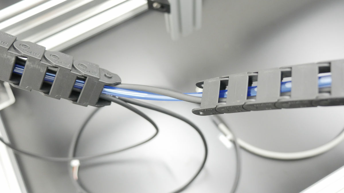
Insert X motor cable and polyurethane tube on cable carrier (X axis).
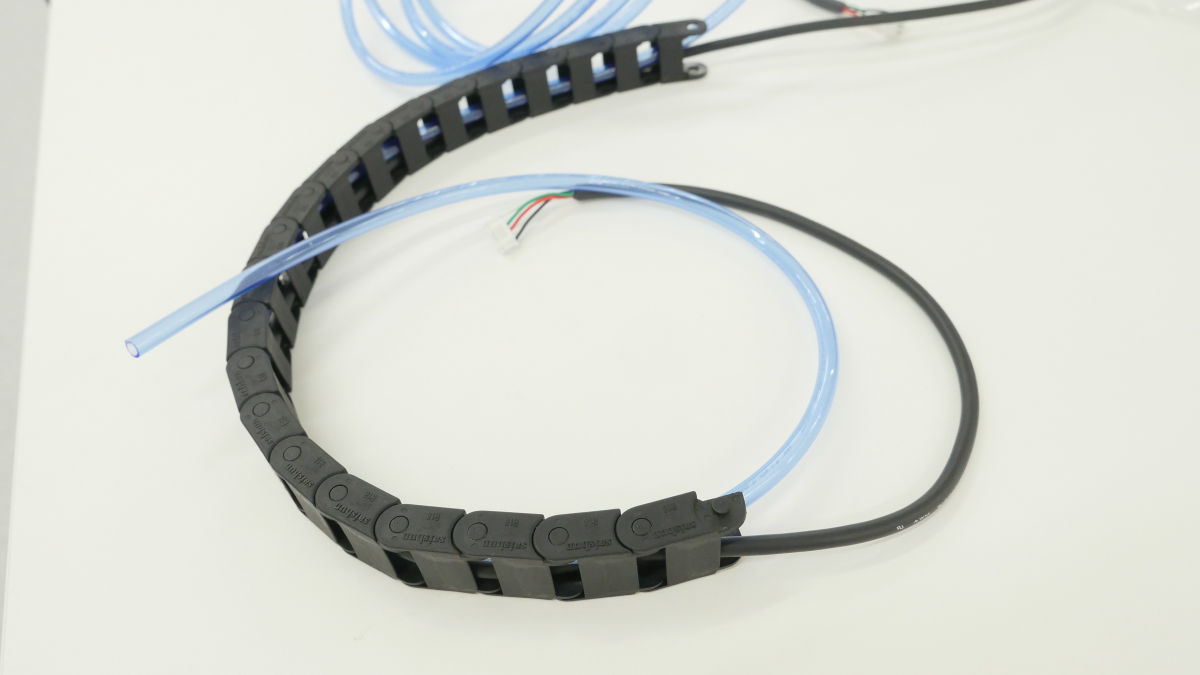
Pass the Y motor L cable and the X1 limit cable through the cable carrier (Y axis) and the Y motor R cable and the X2 limit cable through the cable carrier (Y axis) on the other side as well.
Finally, pass the X motor cable and the polyurethane tube through the cable carrier (Y axis).
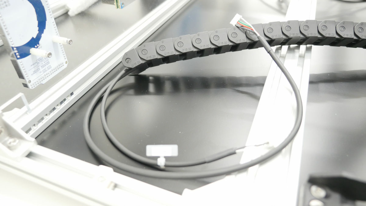
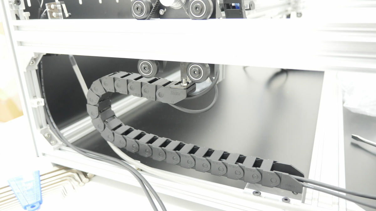
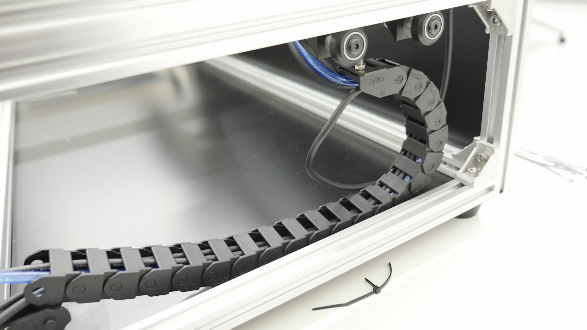
Connect the cable carrier (X axis) to the bracket on the L-shaped aluminum flat bar.

The cable carrier (Y axis) is also connected to the Y axis bracket in the same way.
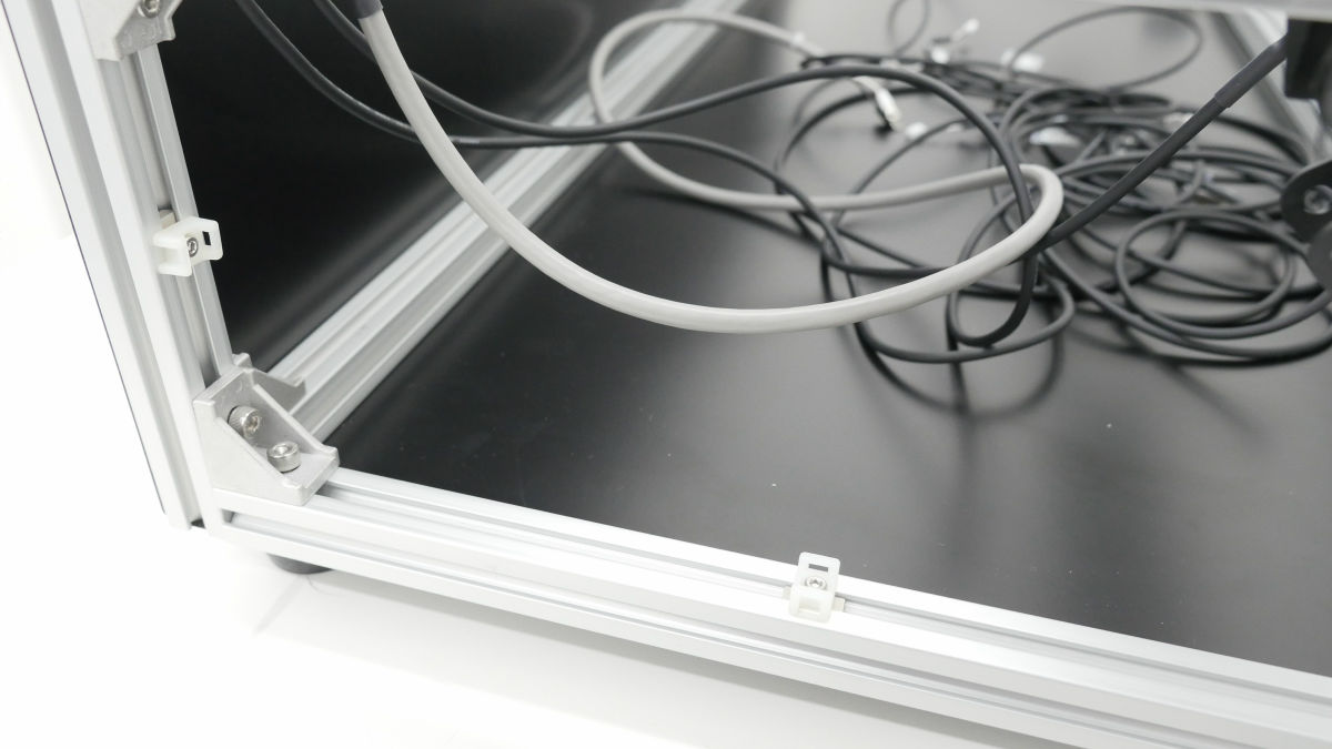
Using wrapping bands to wire together ... ...
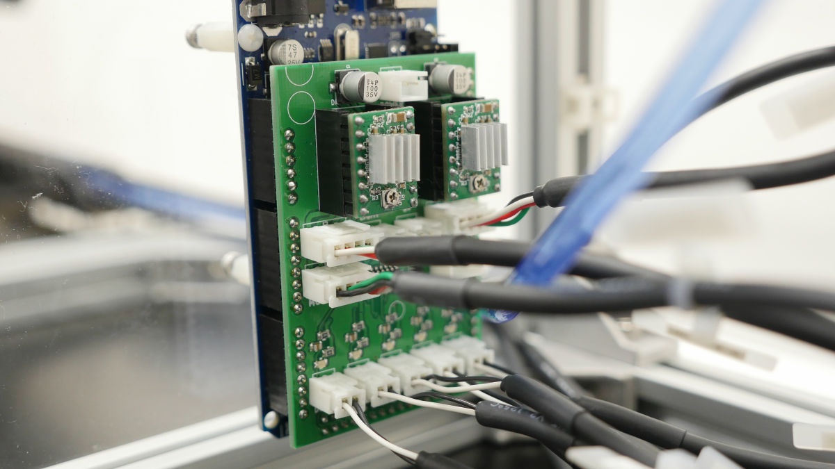
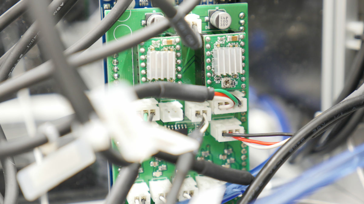
Walk around to Arduino Mega part.
Attach the controller board to Arduino Mega and connect various wires to the controller.
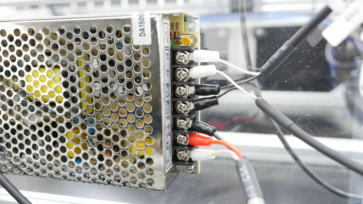
Next, connect the "AC - DC cable", "FAN cable", "Power cable" to the DC power supply.
Attach the cover on the right side of the main unit.
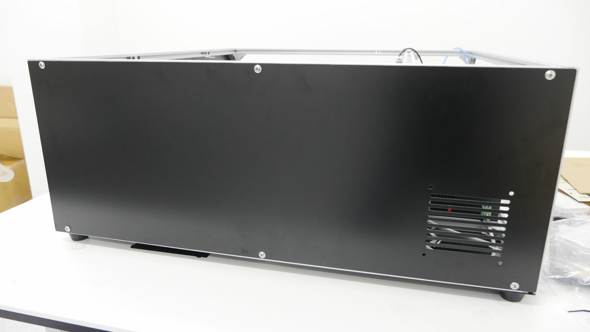
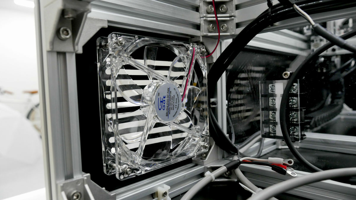
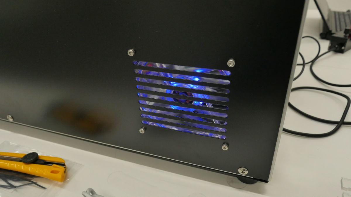
Also install a fan for waste heat.

Attach the cover on the left side of the main body ......
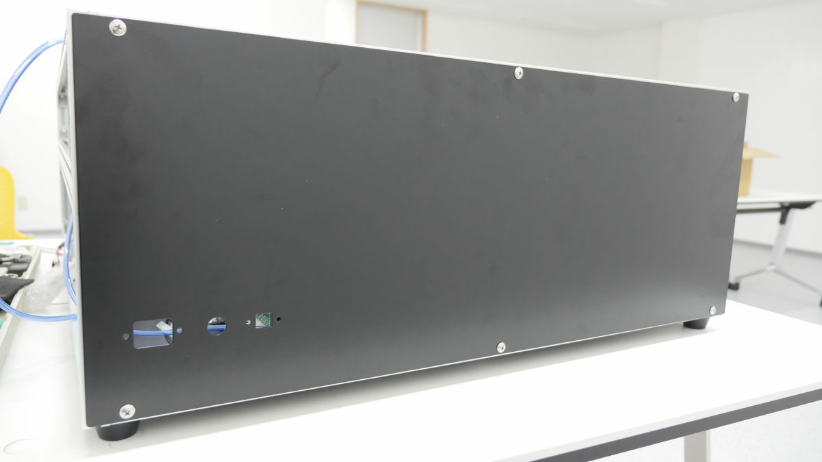
AC main cable with aluminum ferrite ......
It is attached to the cover.
Panel mount USB is also installed.
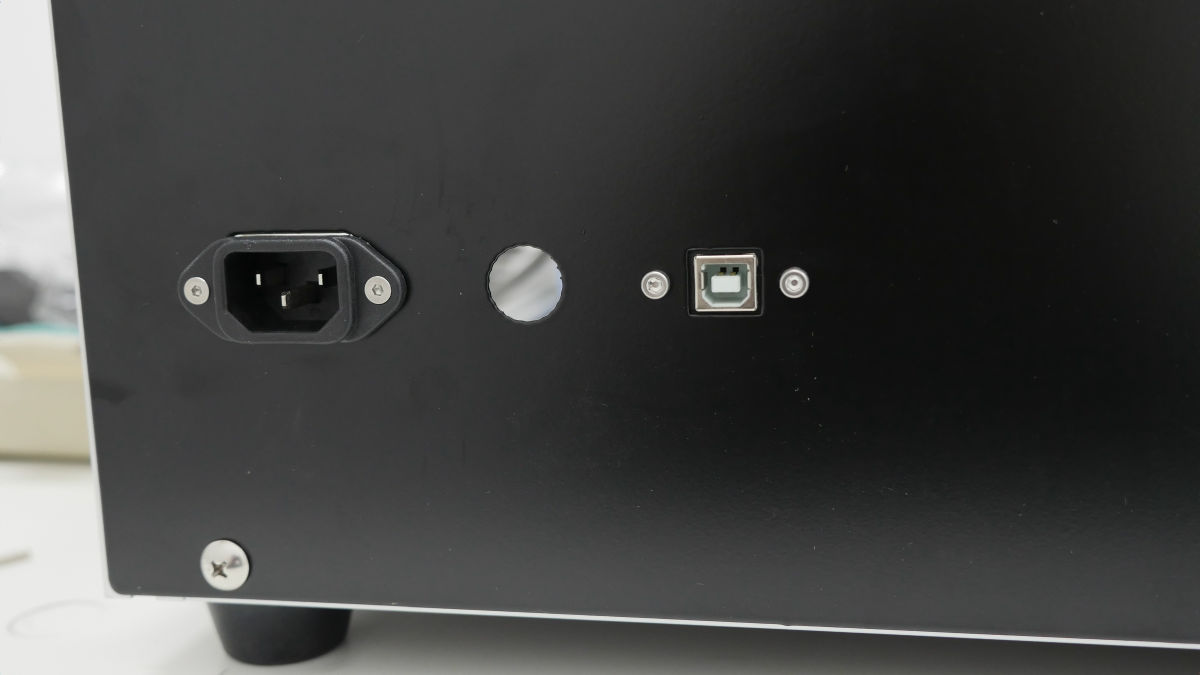
In the meantime, attach the panel touch connector ......
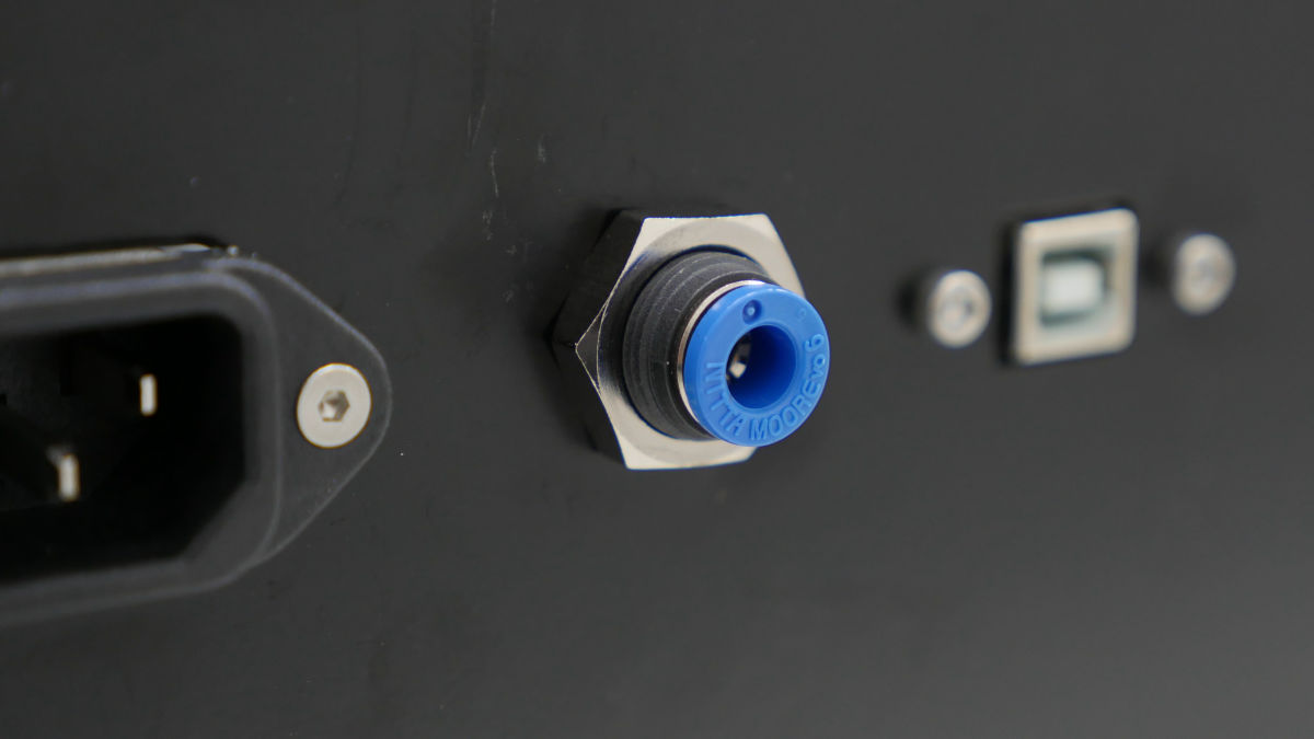
Attached wired polyurethane tube.
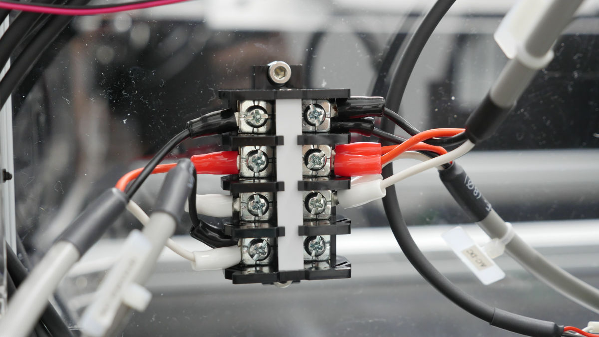
AC mains, AC switch, AC laser, AC-DC cables are connected to the terminal board, wiring connection is completed.
Metal parts of processing bed ......
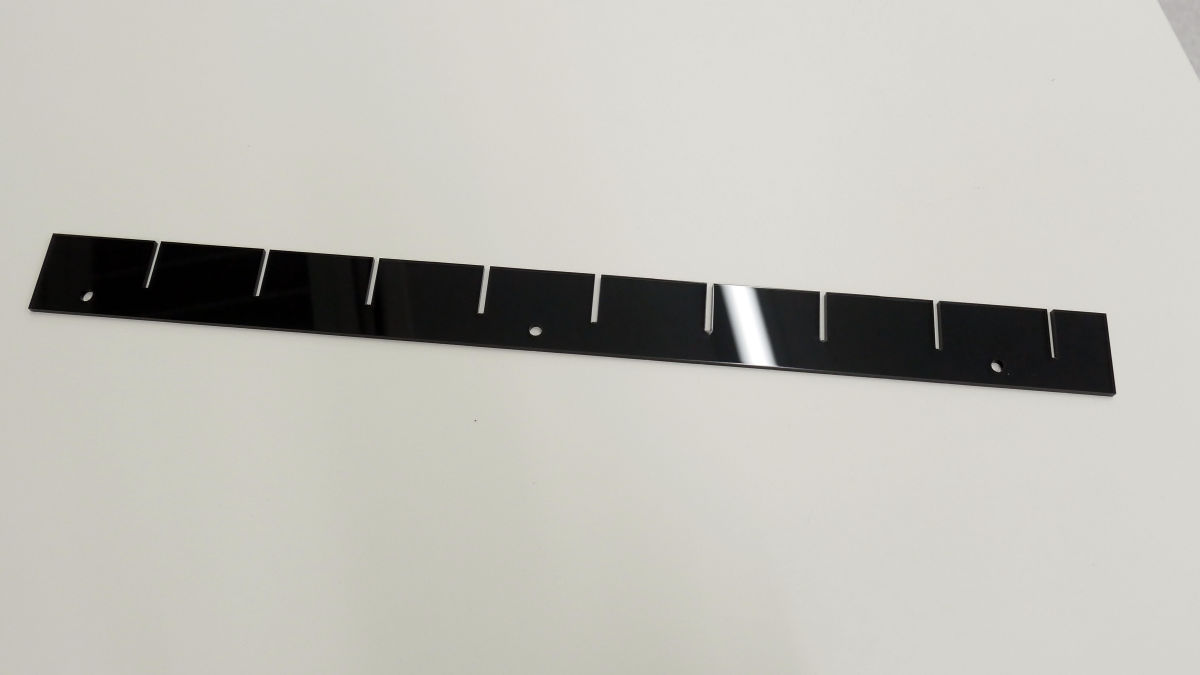
Install in front of inner acrylic.
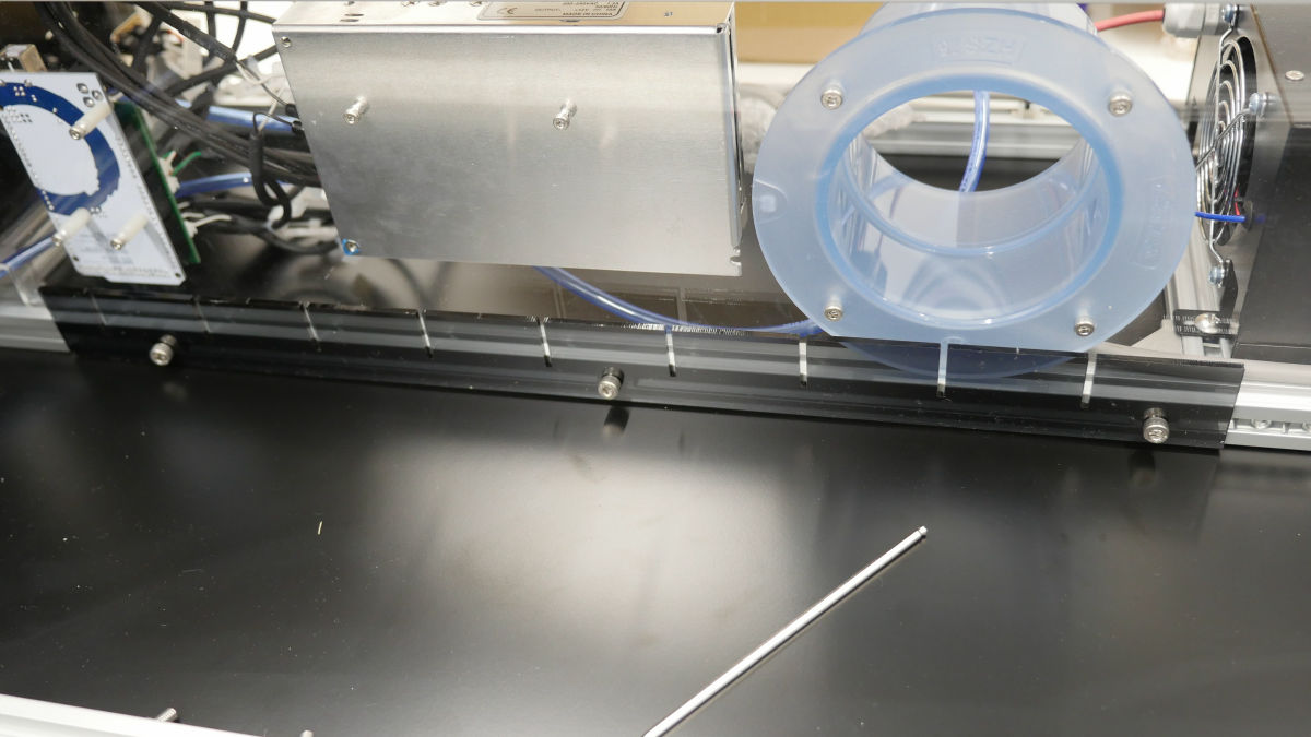
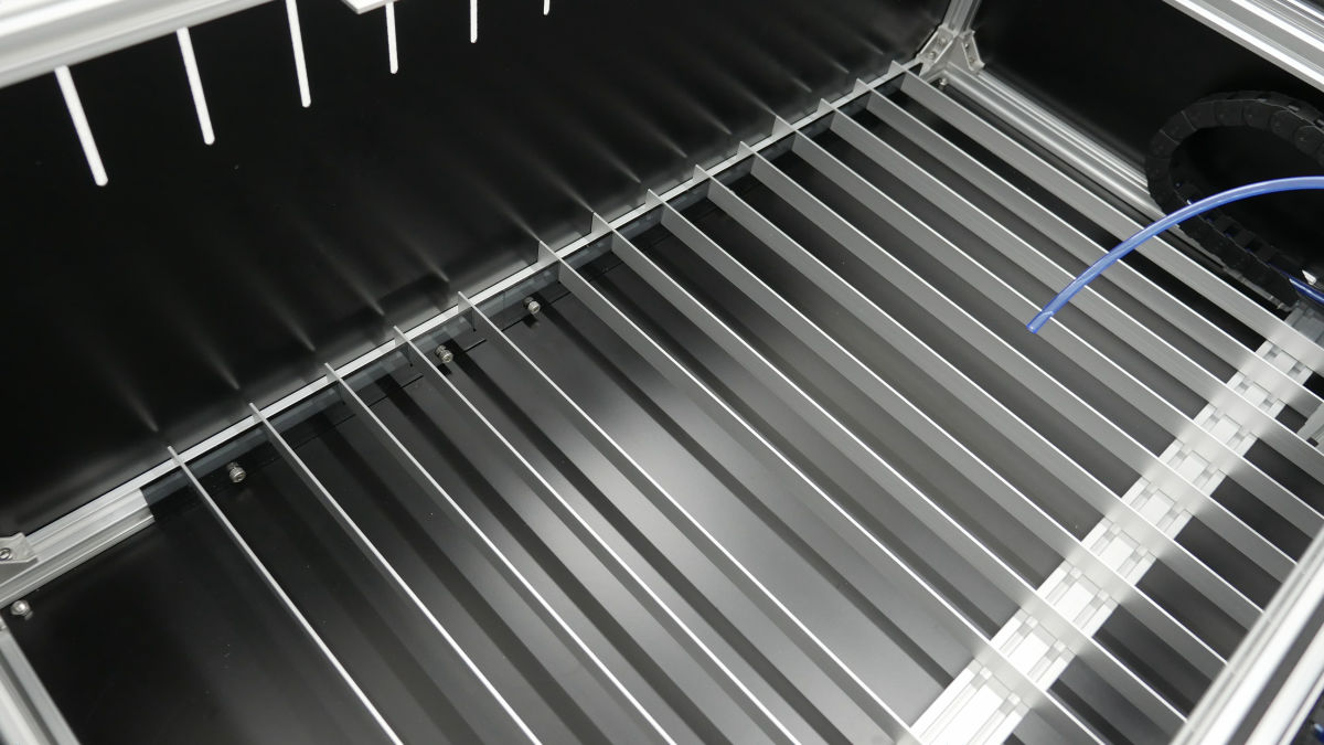
If you attach the processing bed also in front of the back cover on the other side, you can set it by fitting an aluminum flat bar according to the groove.
Next, move the X axis unit and the Y axis unit, adjust the position so that it hits the limit, and fix it.
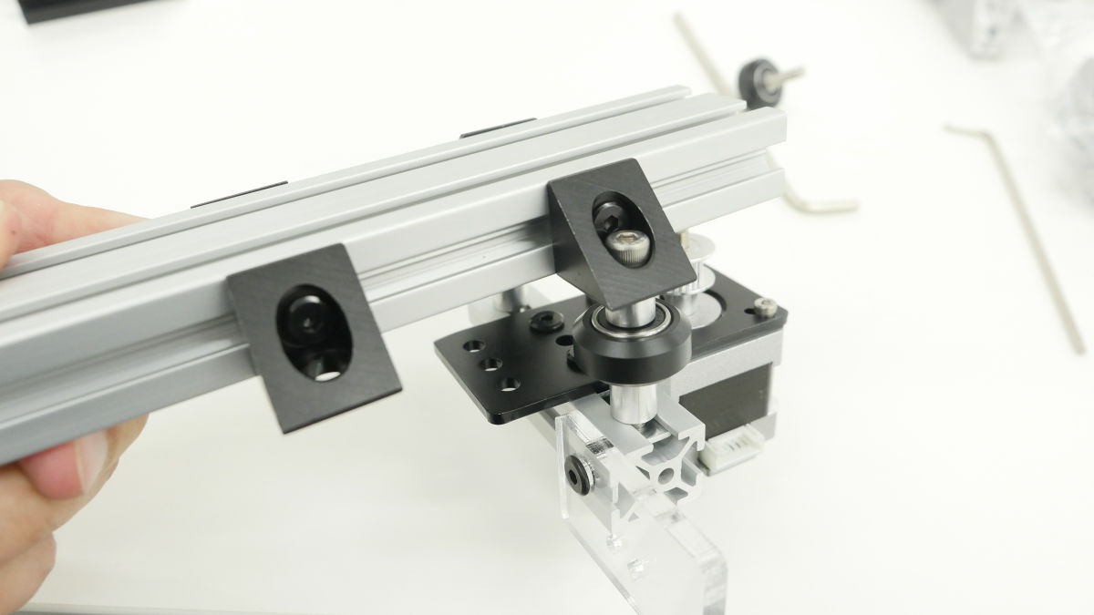
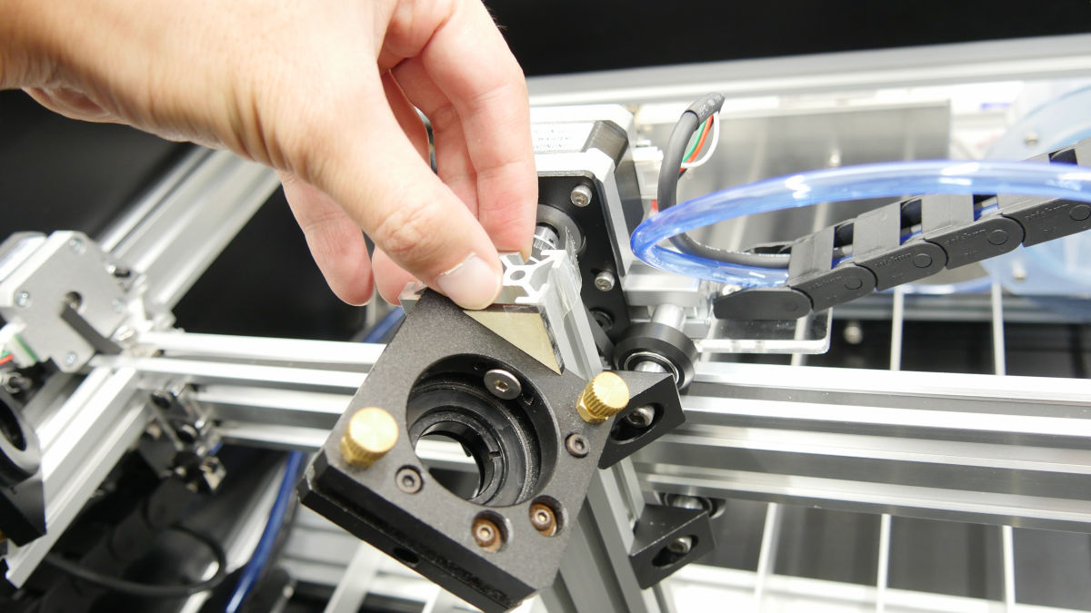
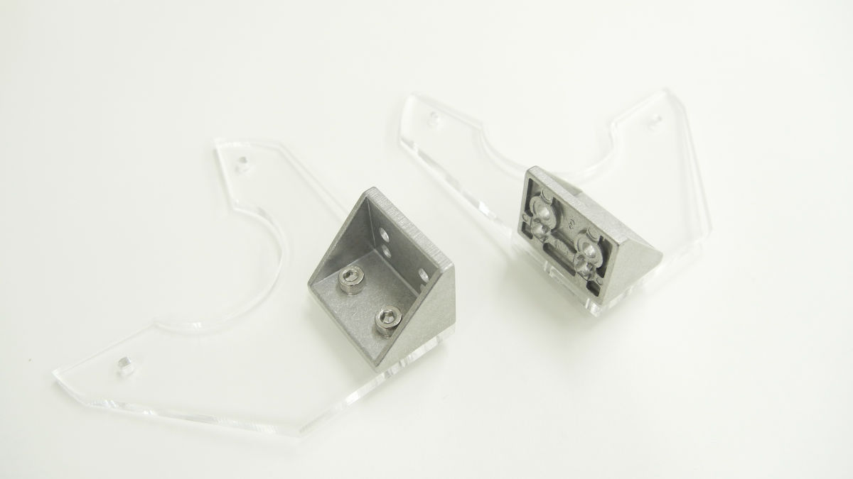
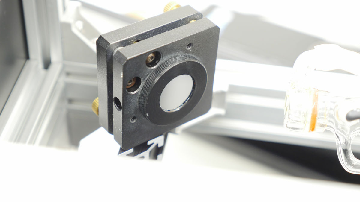
· Mirror mount
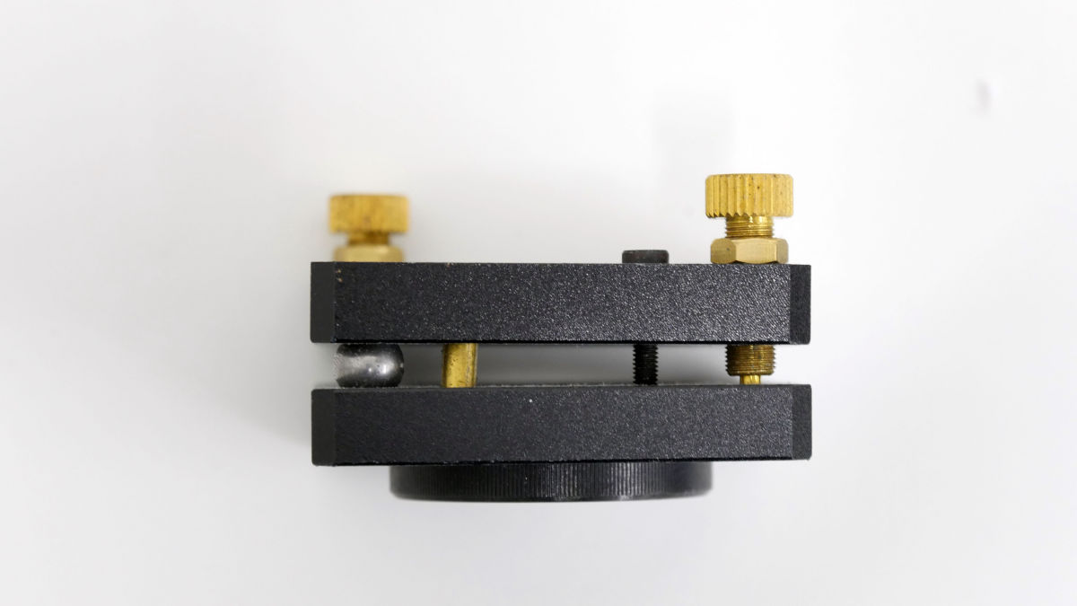
This is a mirror mount for reflecting the laser.
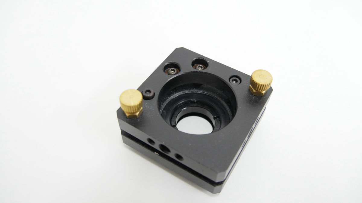
Adjust the screws attached to the diagonally so that the gaps are parallel.
Position the aluminum frame for the first mirror in the middle aluminum frame of the front using 180 x 46 mm acrylic and install.
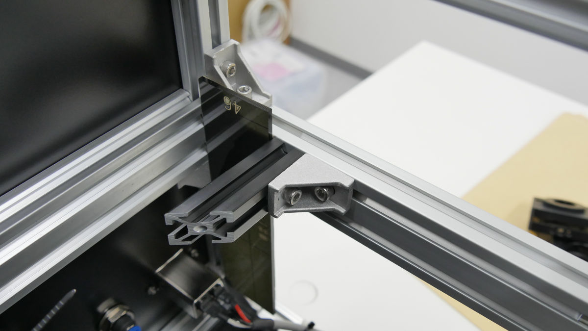
Mount the mirror mount on it.
Fix to fit the plane cut to 45 degrees.
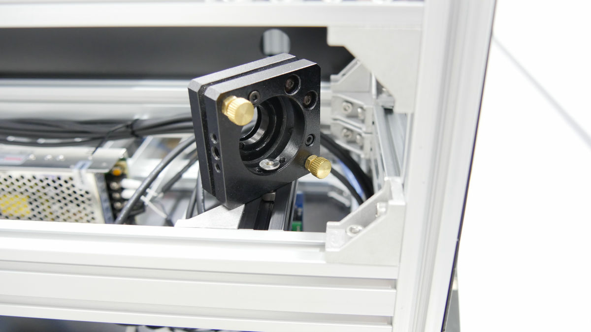
Similarly, a mirror mount is attached to the second mirror aluminum frame.
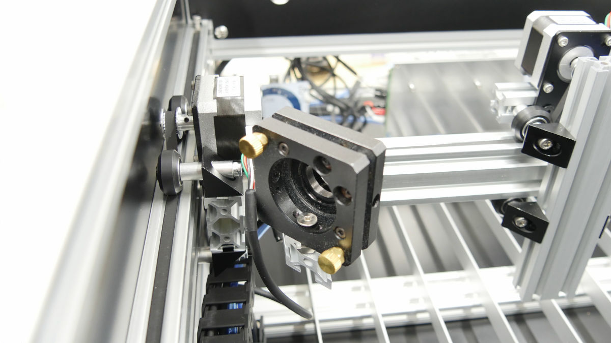
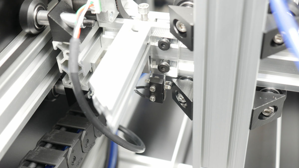
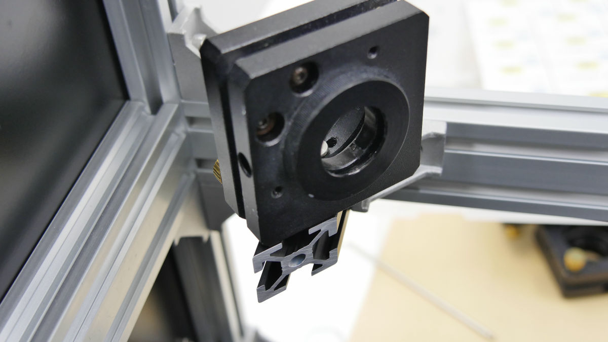
Mount the mirror mount also on the X axis unit while aligning with right triangle acrylic.
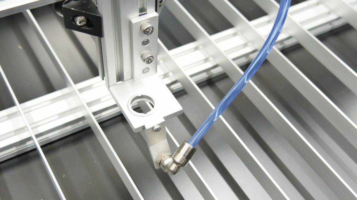
Attach the T nut to the lens nozzle ... ...
Mounted on X axis unit.

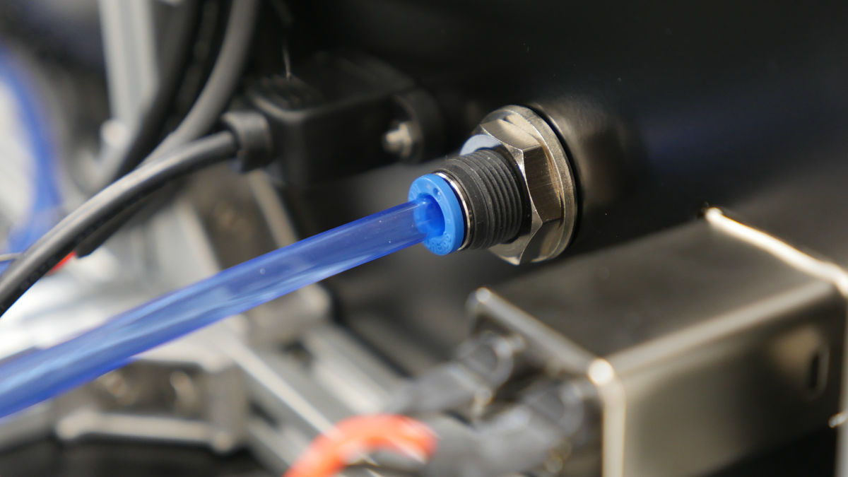
Attach the air assist holder to the tip.
It is OK if fitting a heat resistant one-touch fitting and attaching a polyurethane tube.
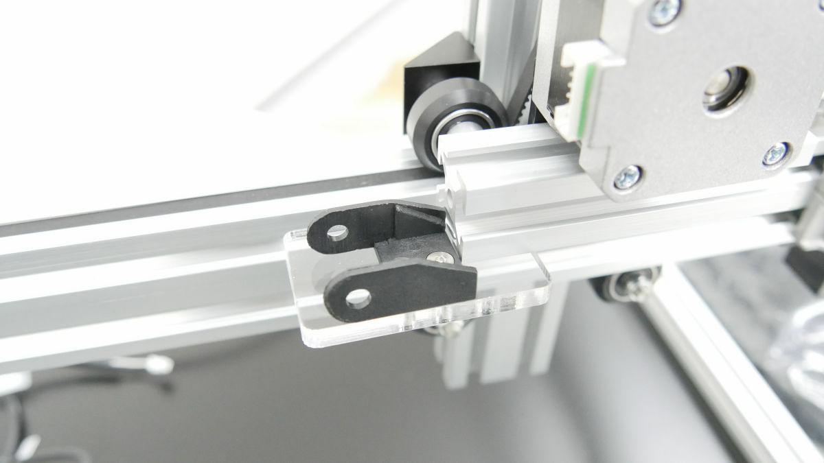
· Top cover
Assemble the aluminum frame for the top cover ... ...
I attached a door limit.

To the hinge which was attached in advance ......
Fixed.
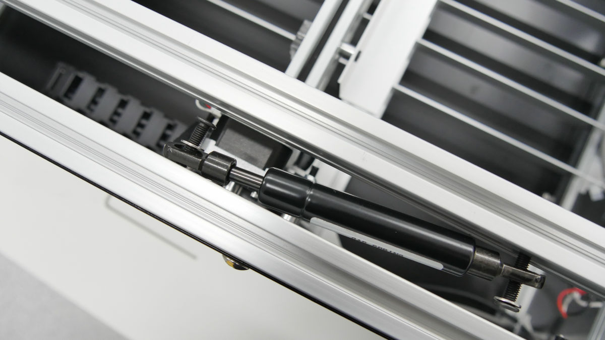
Gas spring is attached to T nut which was put in the main frame.

Attach acrylic cover ... ...
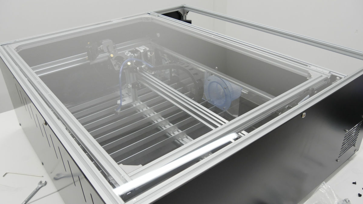
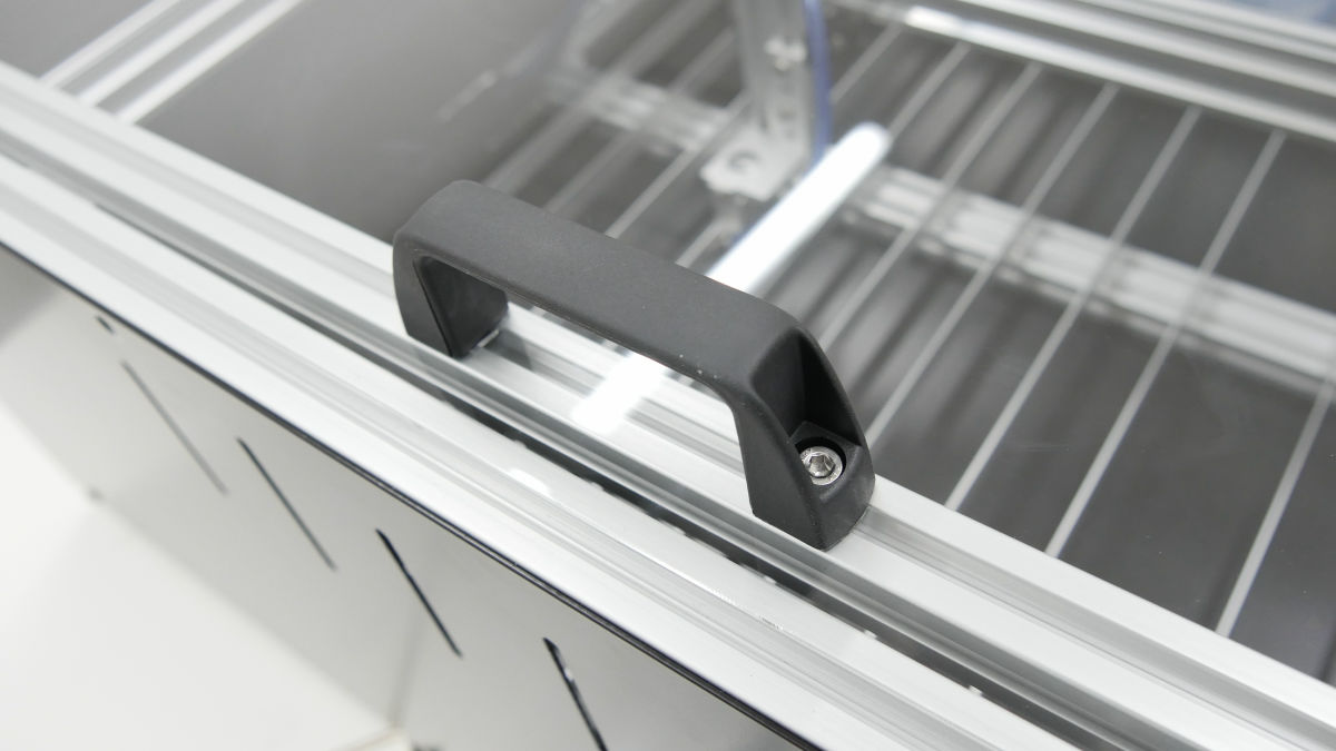
Completion of the top cover after attaching the handle.
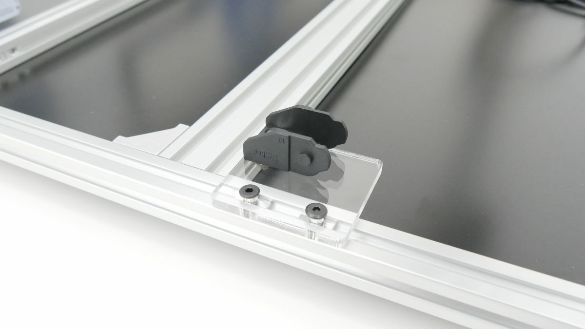
Adjust the acrylic position so that it contacts the door limit when the top cover is closed.
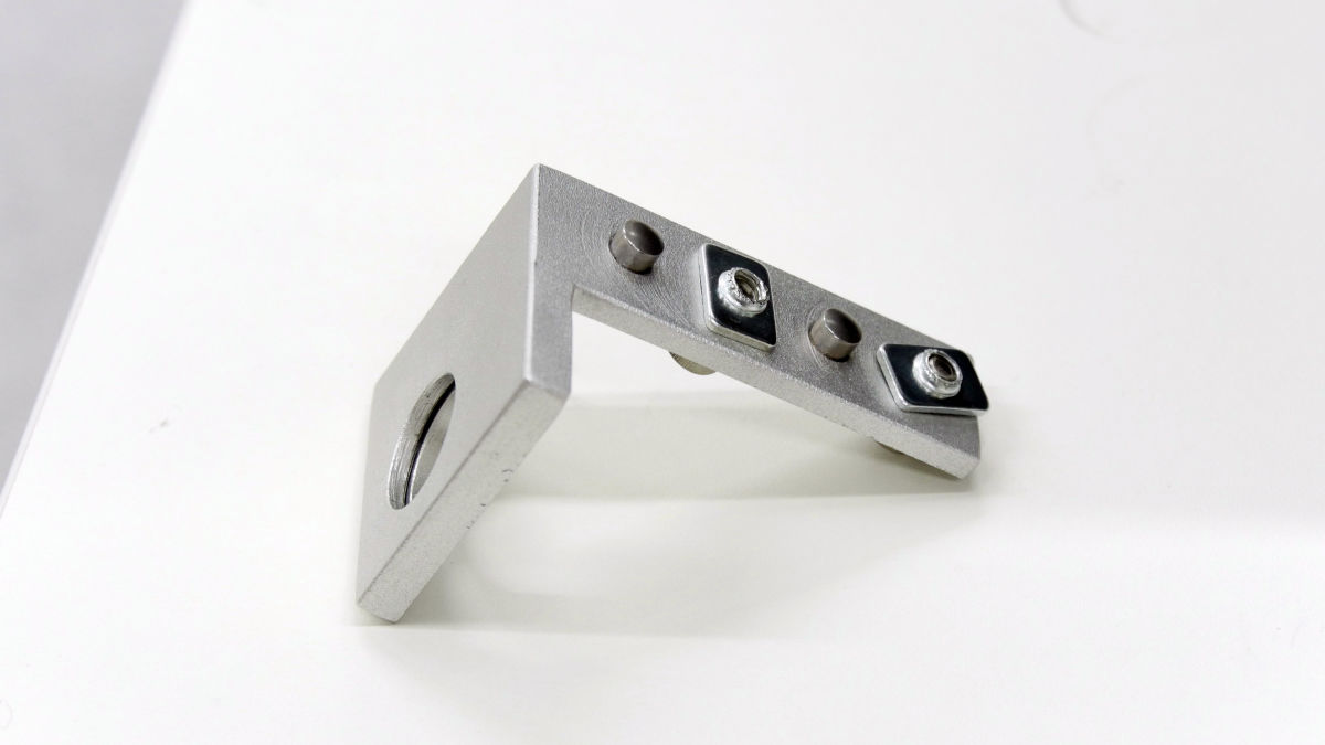
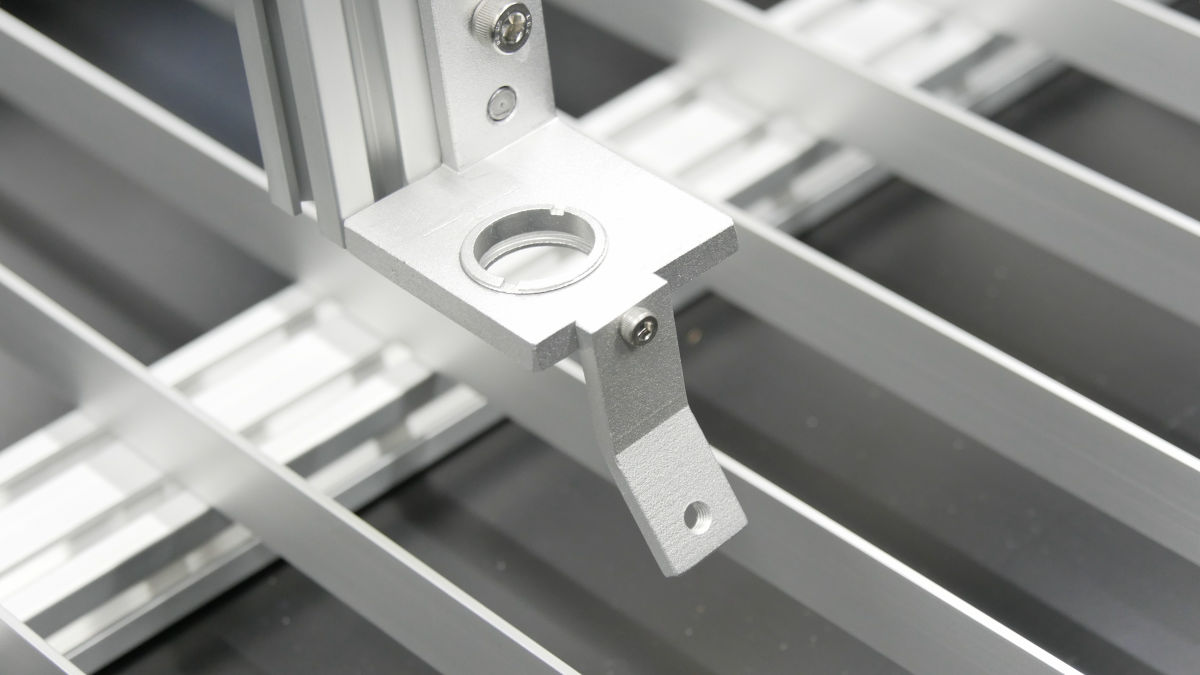
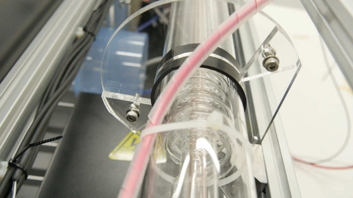
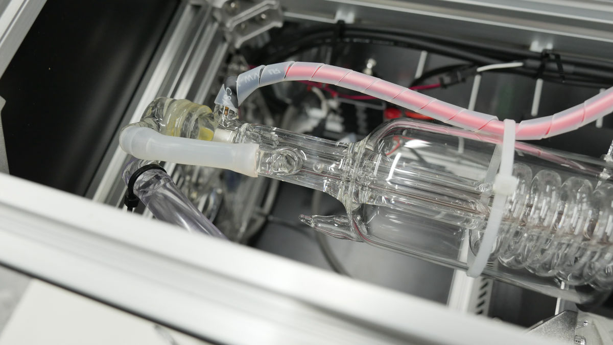
· Laser tube
Laser tube support under, fitted with protrusion reversing bracket.
Attach it to the body frame ......
Put the fixing rubber in the semicircular recess and ......
Attach the laser tube.
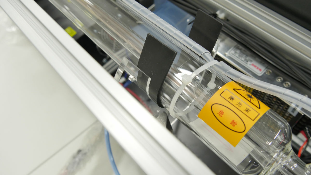
Firmly fix the laser tube with the laser tube support top. Make sure there is no rattling.
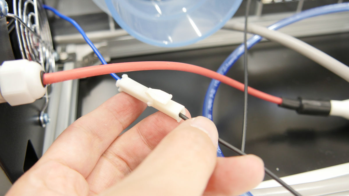
Wire the cable of the laser tube ......
Also wire the fan cable.
· Optical axis adjustment
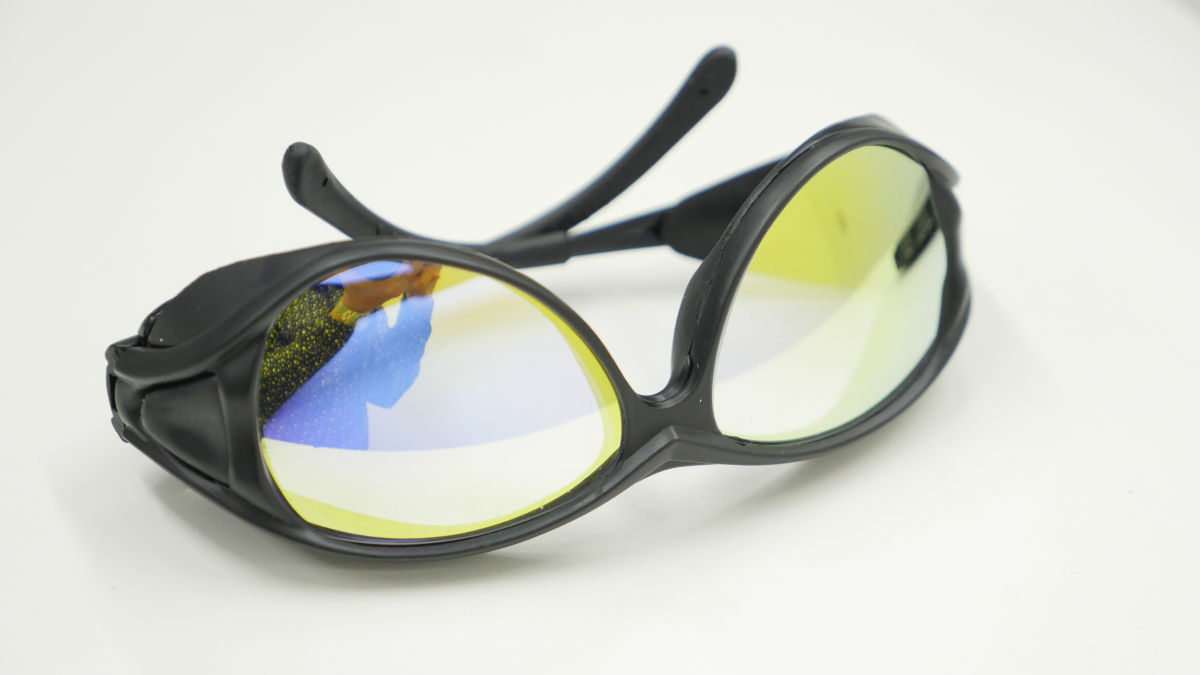
From here we will adjust the optical axis of the laser. Adjust the optical axis by attaching protective eyeglasses.
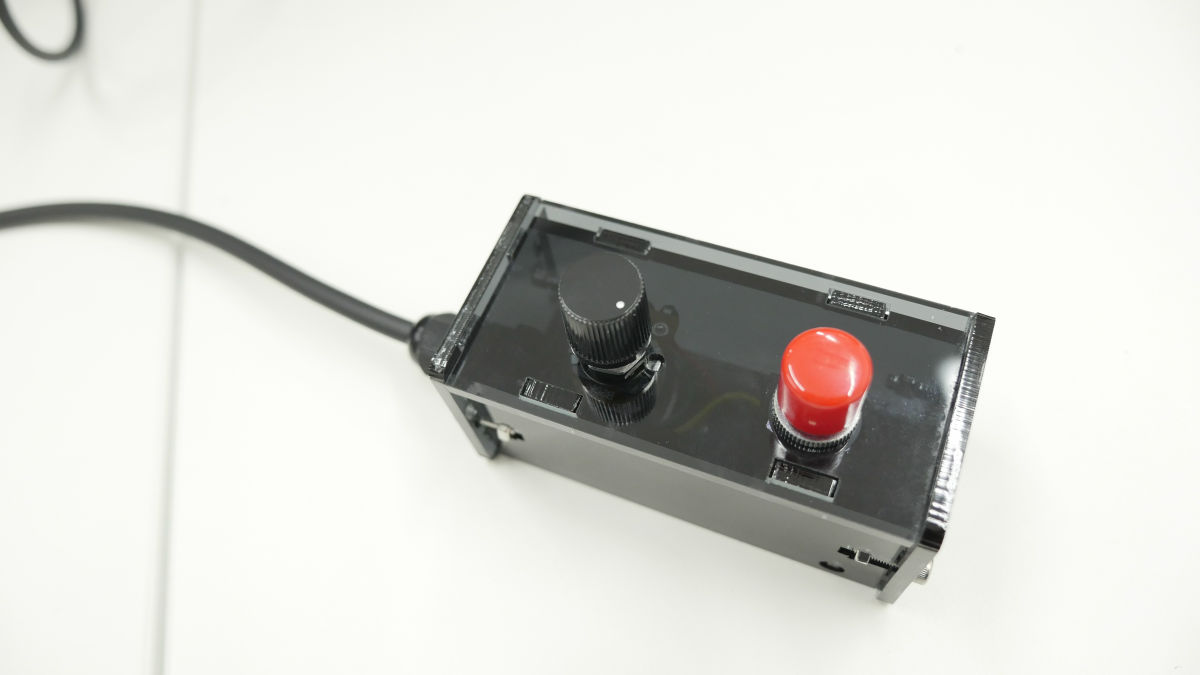
Connect the optical axis adjustment button to the laser power supply.
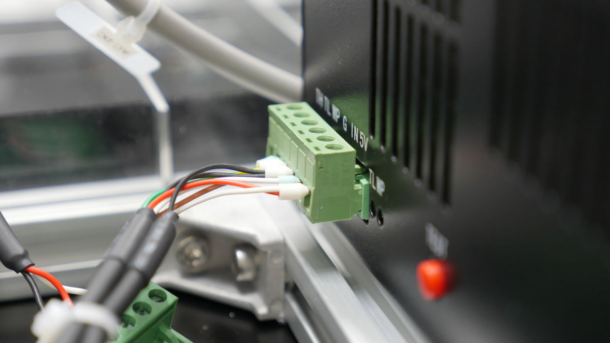
The other connector is connected to the controller. .
The left knob is for laser output adjustment and the right button is laser irradiation button. The point is to turn the knob clockwise and minimize the output.
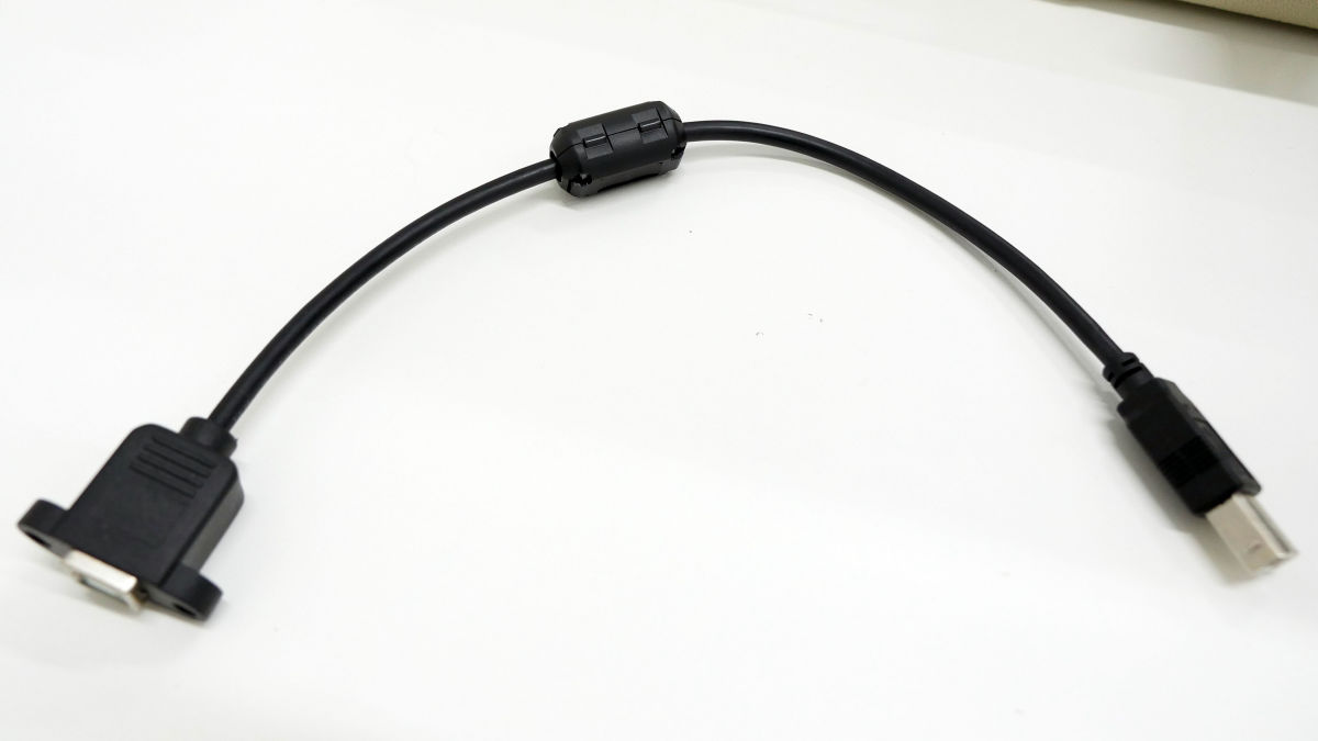
Wire the USB ......
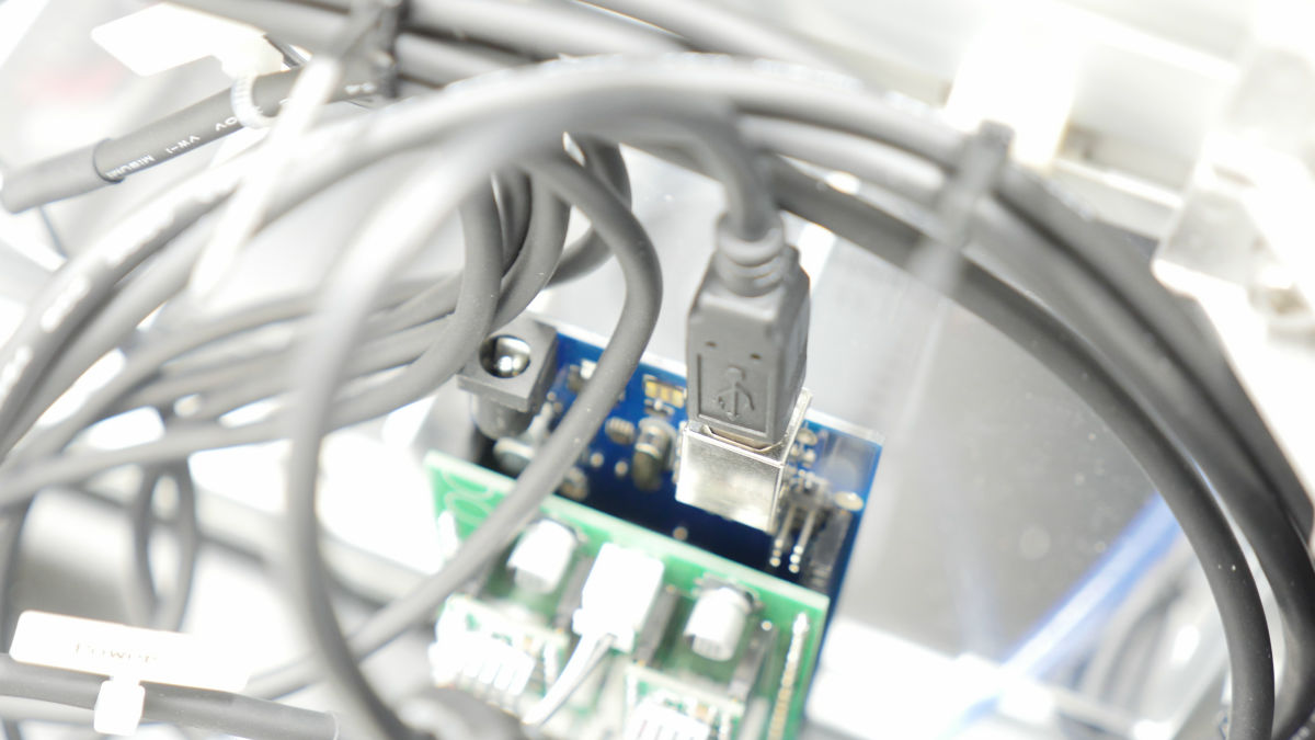
Please connect to the PC using the USB port of the panel.
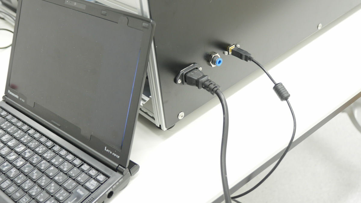
· Software installation
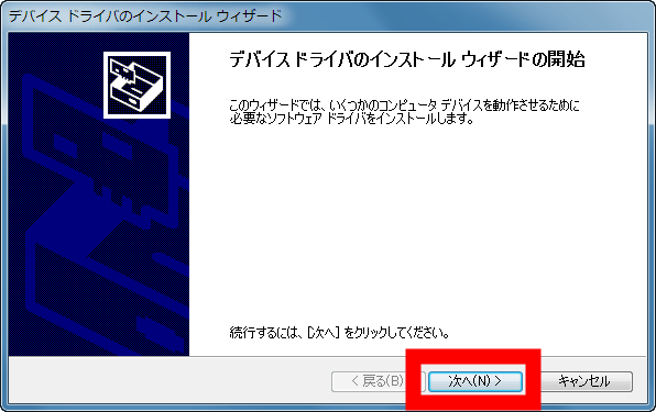
First, install the driver for the control board connection. Since I use the PC of Windows 7 this time, I download the driver for Windows from the following link destination.
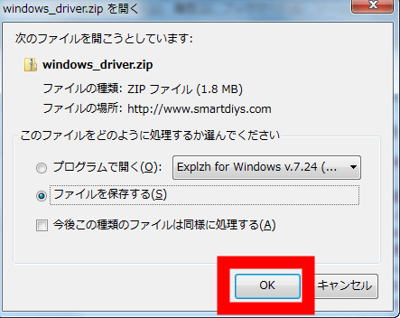
http://www.smartdiys.com/manual/wp-content/uploads/2015/02/windows_driver.zip
Click "OK".
Click "Next".
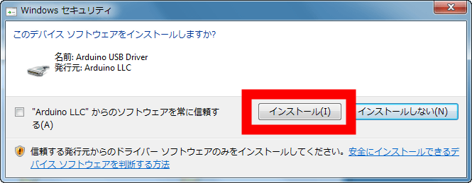
Click "Install".
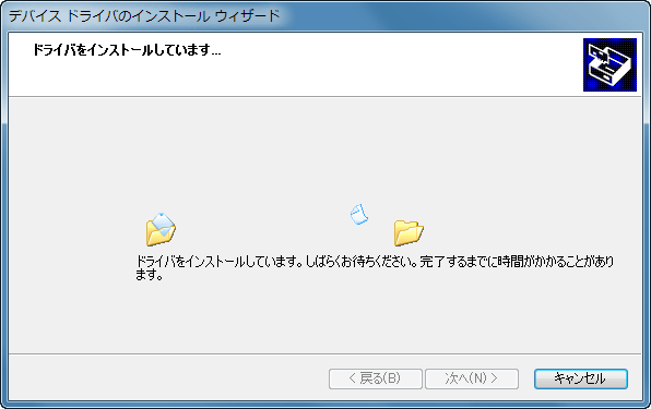
As the driver installation starts, wait for a while ......
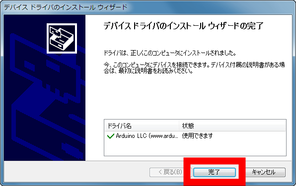
Click "Finish" and OK.
Next, installation work of Smart Laser CO2 exclusive software for Windows. Download the software from the following link.
http://www.smartdiys.com/manual/wp-content/uploads/2015/09/windows_smartlaser_co2.zip
Click "OK".
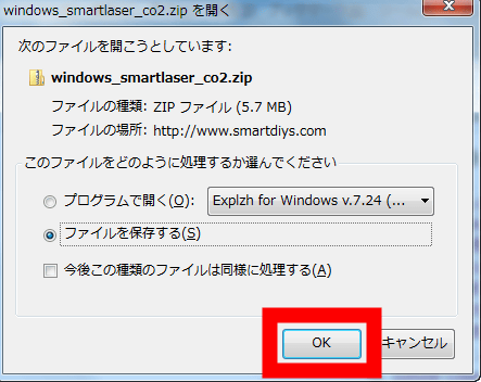
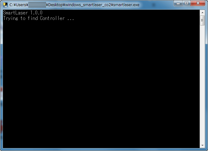
The downloaded ZIP file is called "ExplzhWhen you execute "smartlaser.exe" in the folder by unpacking it with software such as "Welcome, please wait for a while as the window opens.
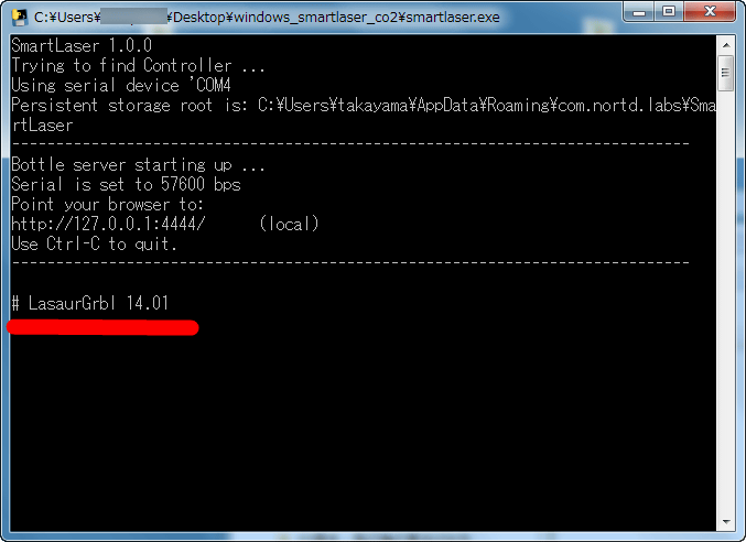
If "# LasaurGrbl XX.XX" is displayed, it is successfully connected.
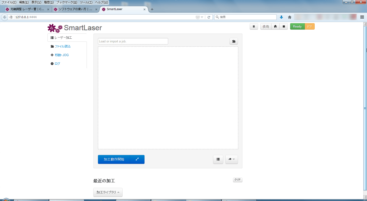
Smart Laser CO2 operates from the browser. In the latest Chrome or Firefoxhttp://127.0.0.1:4444/", The operation screen will be displayed. From this screen, you can adjust the position of the laser, execute the program and various operations of Smart Laser CO 2. It is OK to adjust the optical axis of the laser while keeping this screen open.
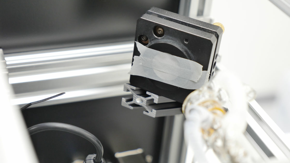
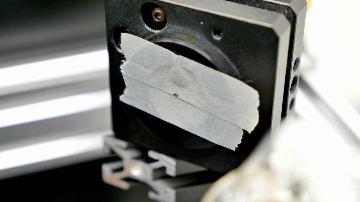
Finally, optical axis adjustment start. First of all, we attach a masking tape to each mirror mount.
Power ON.
OK if the fan glows blue.
Push the laser irradiation button and check the position where the laser hits. Please note that masking tape burns immediately if laser output is not minimum.
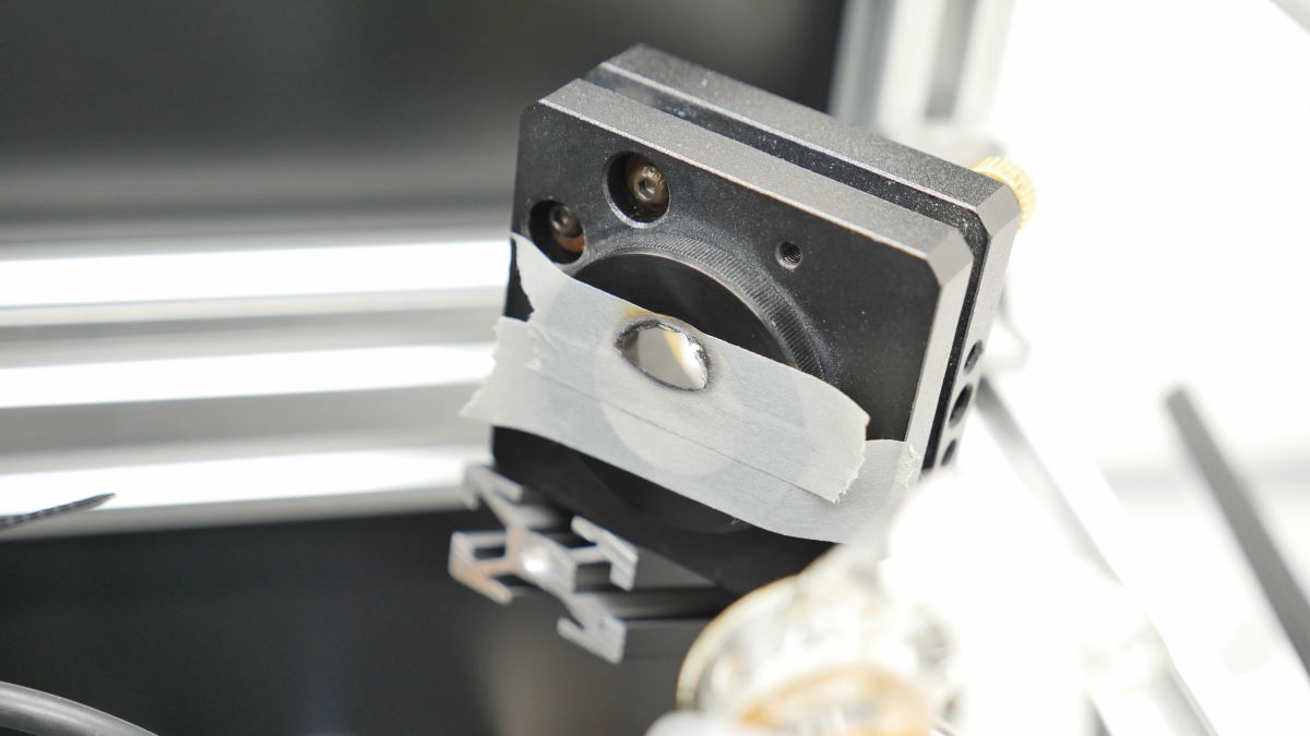
Adjust the diagonal screw of the laser mount and if laser irradiation is near the center OK.
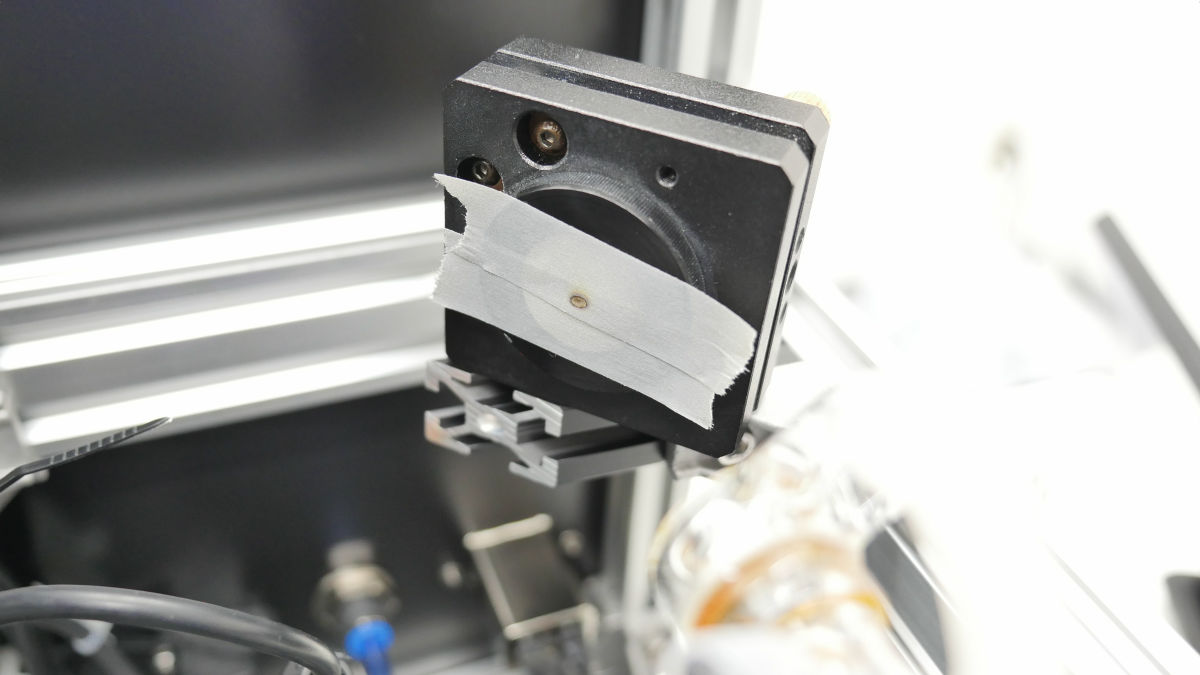
After laser mount adjustment, remove the front part from the mirror mount.


Then remove the mirror fixing screw ... ...
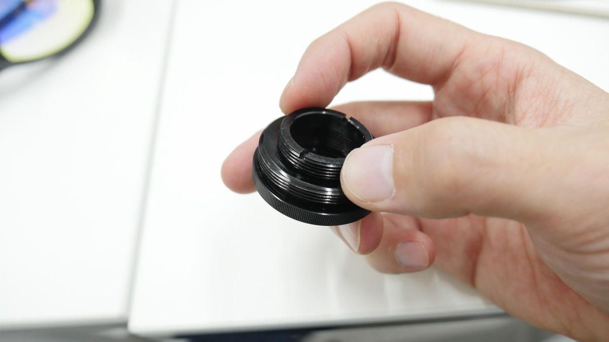
Reflecting mirror attached.
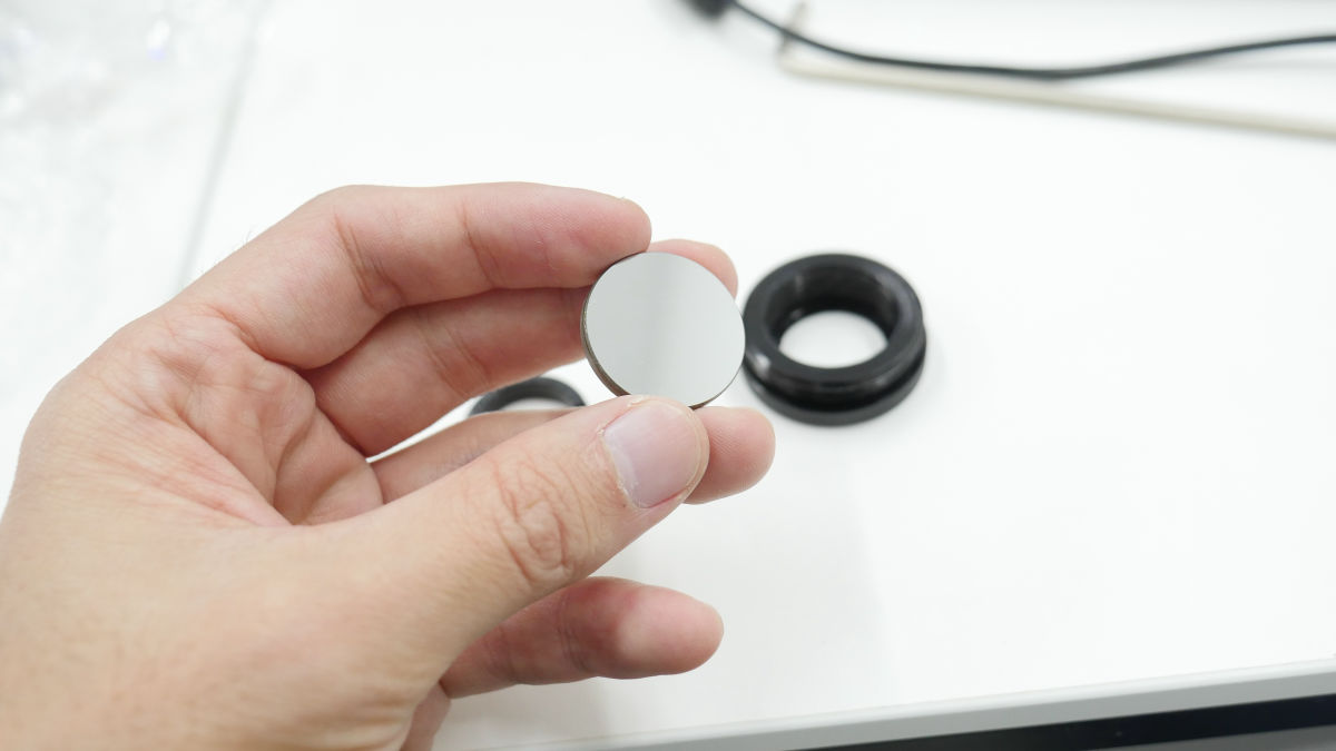
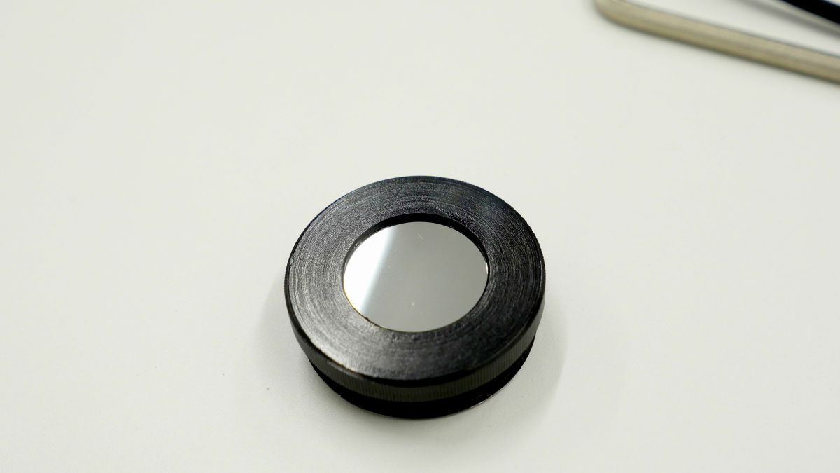
Return the mirror to the mirror mount and OK.
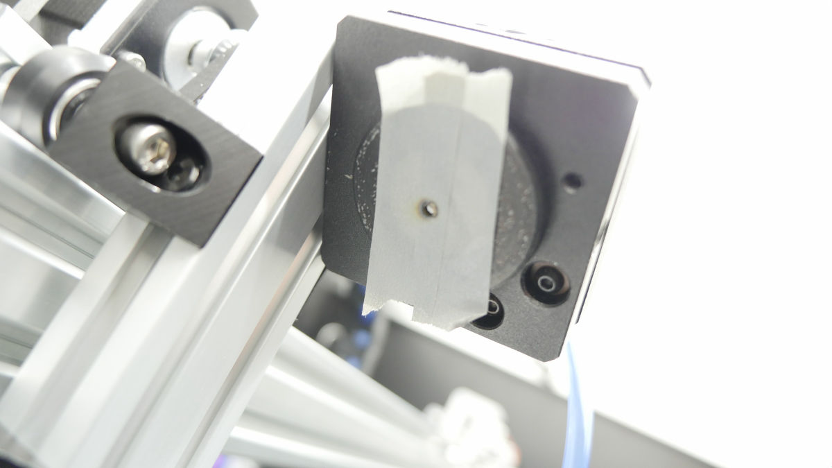
Next is the adjustment of the optical axis of the second mirror. As before, adjust the screws on the mirror mount and adjust the laser so that it is irradiated near the center.
The third mirror of the X axis unit is also adjusted similarly.
Finally it will be OK if the laser head part is also the center.
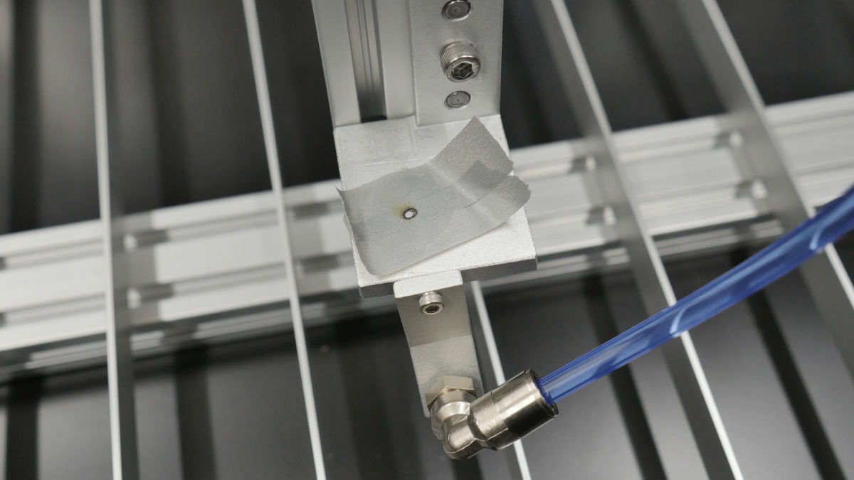
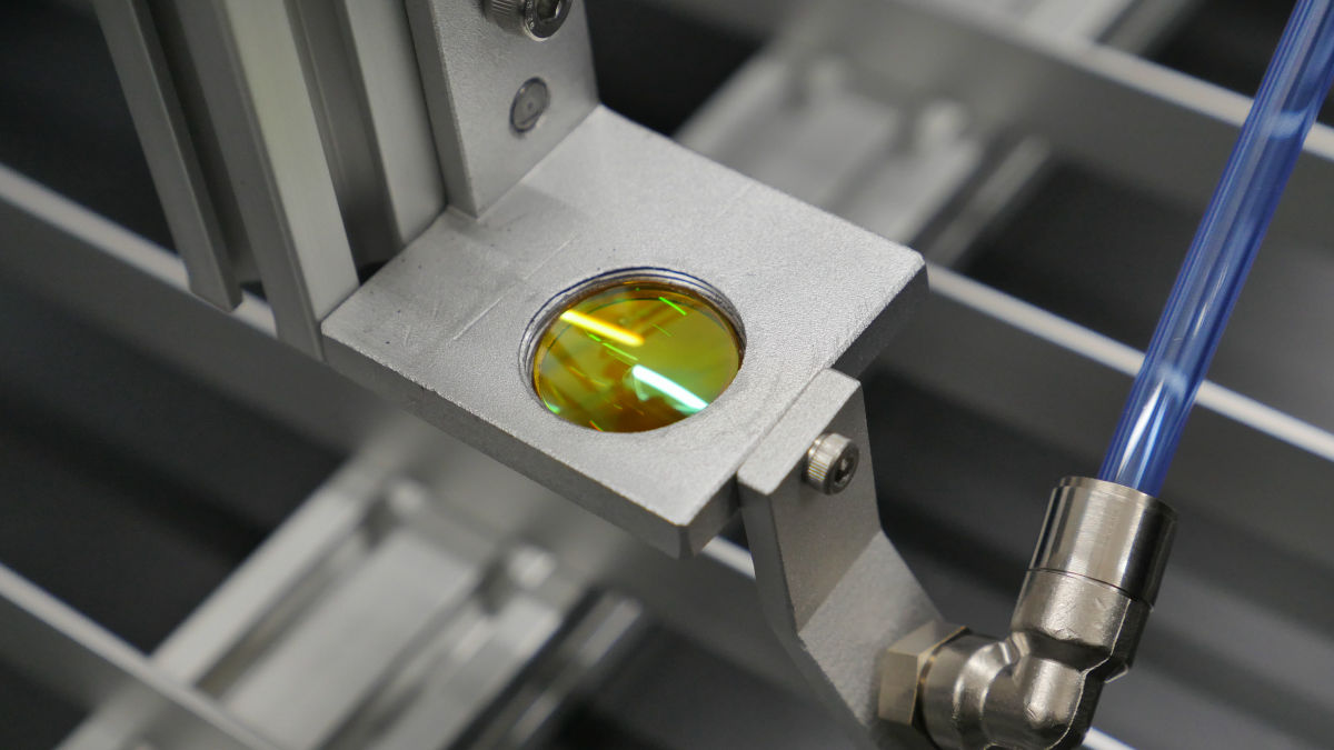
Attach the condenser lens, adjustment of optical axis is completed.
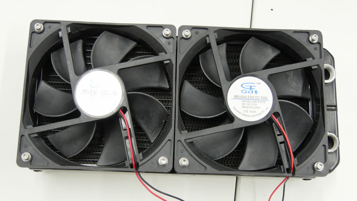
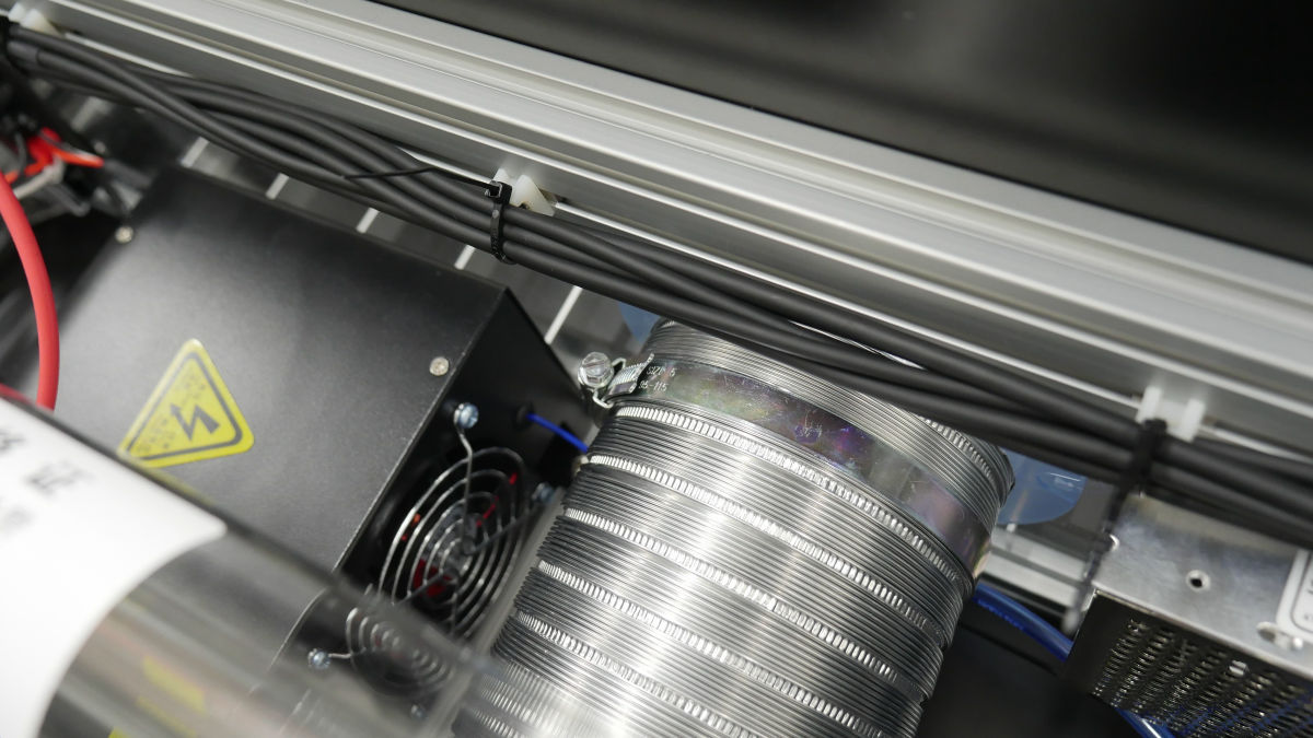
· Water cooling kit
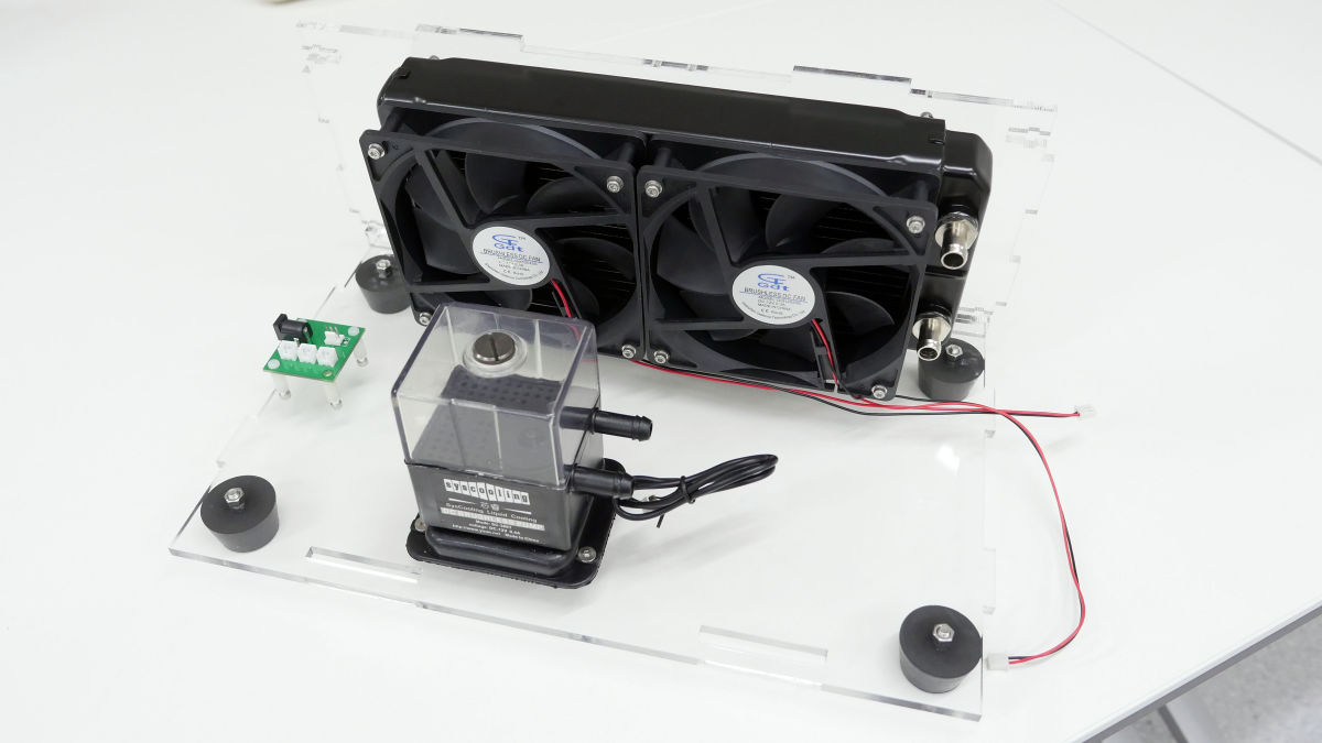
We will make an optional water cooling kit. Since the CO 2 laser tube becomes high temperature, it seems that the water cooling kit can be said to be indispensable equipment in order to stably perform long processing. First of all, install two 12cm fans on the radiator ......
Hose fitting fitted.
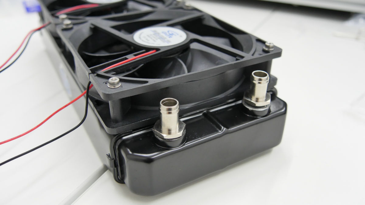
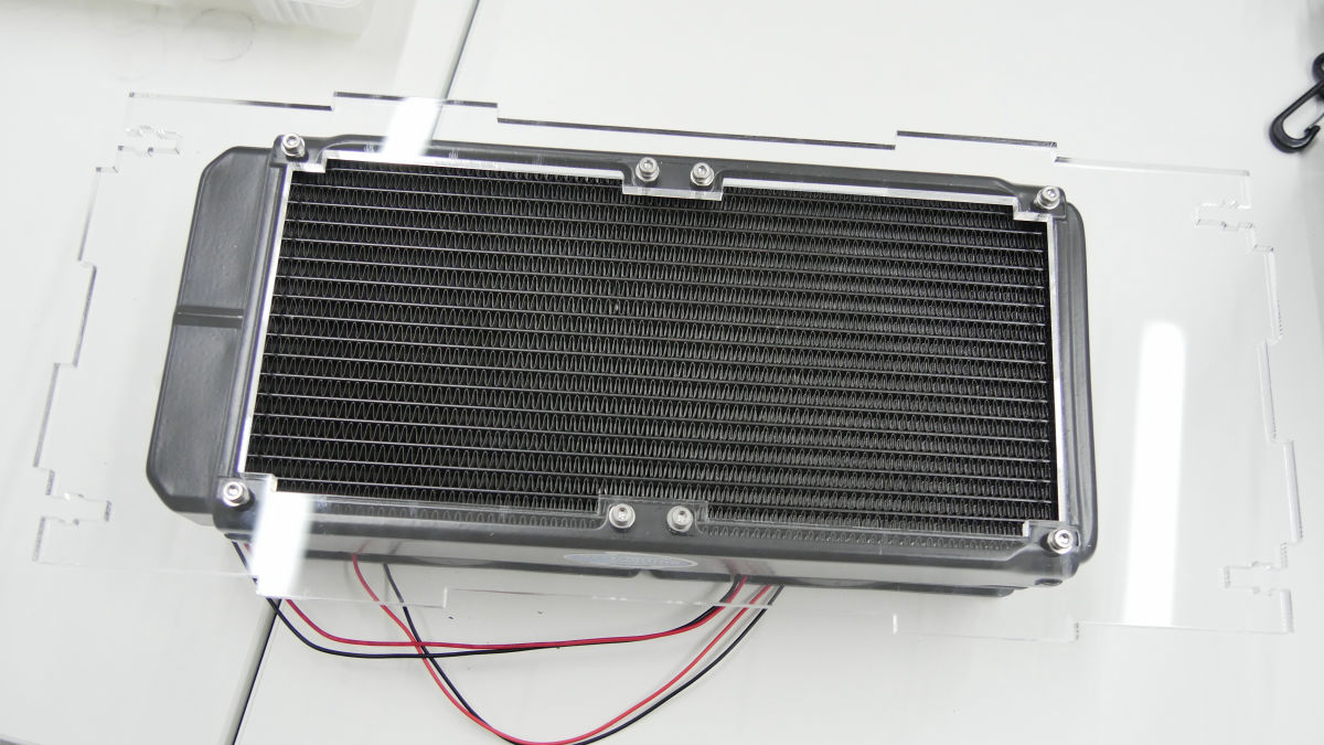
Attach the cover to the radiator.
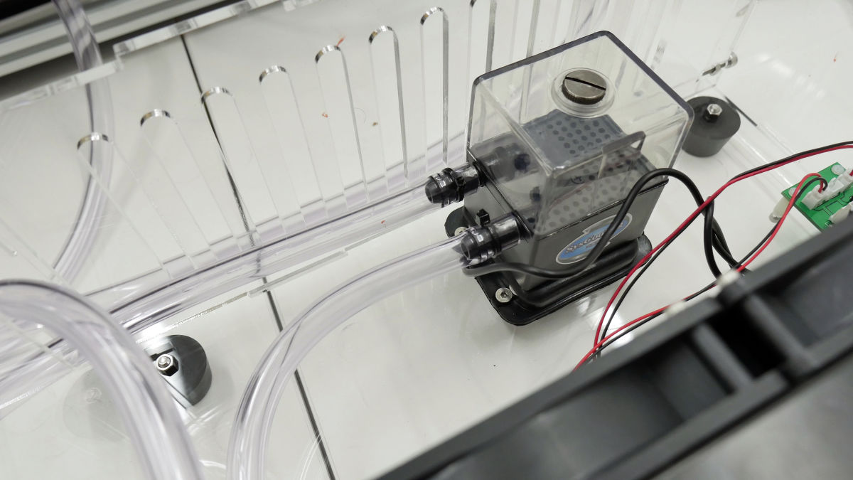
Rubber stand mounted on cooling pump.
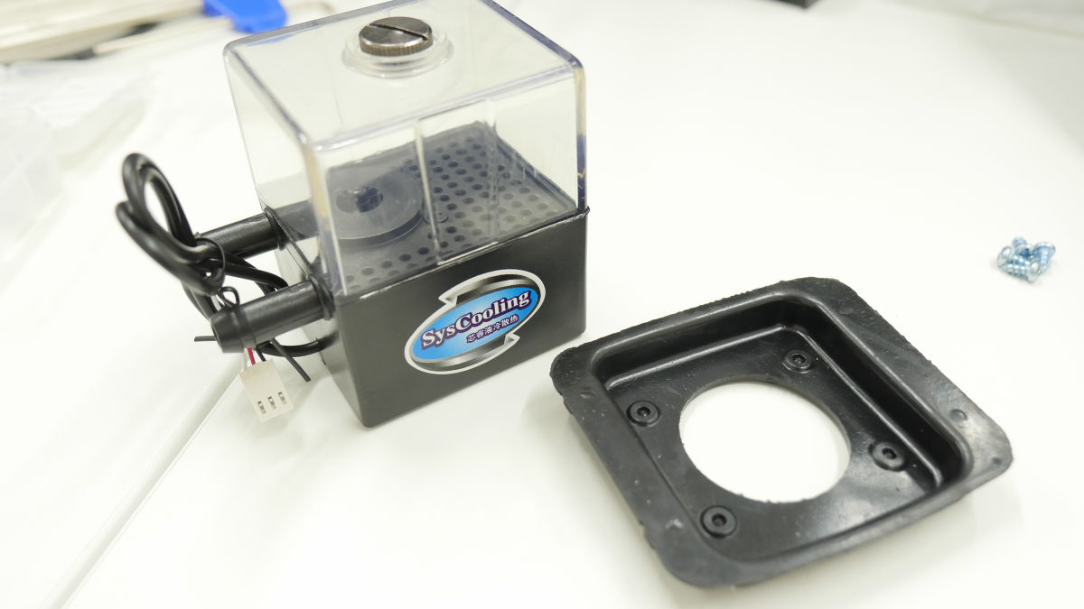
Attach the rubber feet, water cooling pump, power supply wiring board to the bottom acrylic panel and fit the radiator part.
Incorporating side acrylic ......
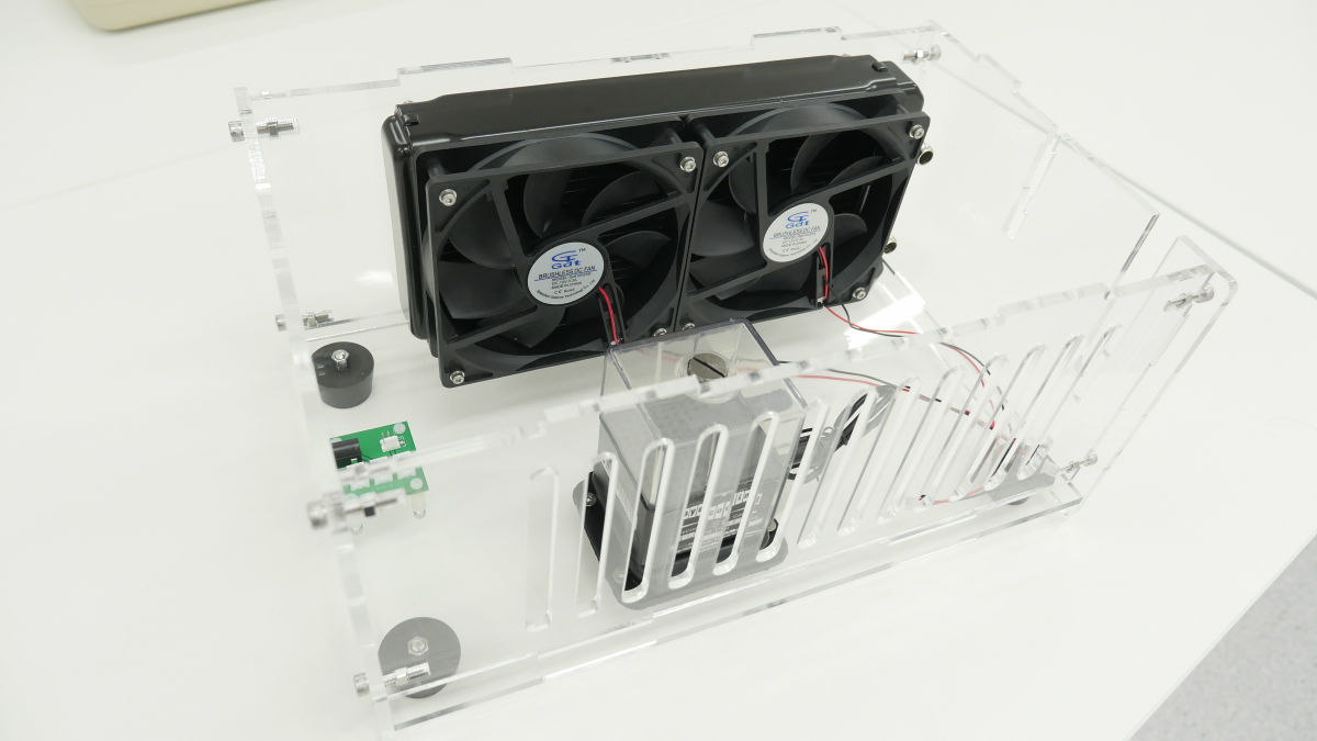
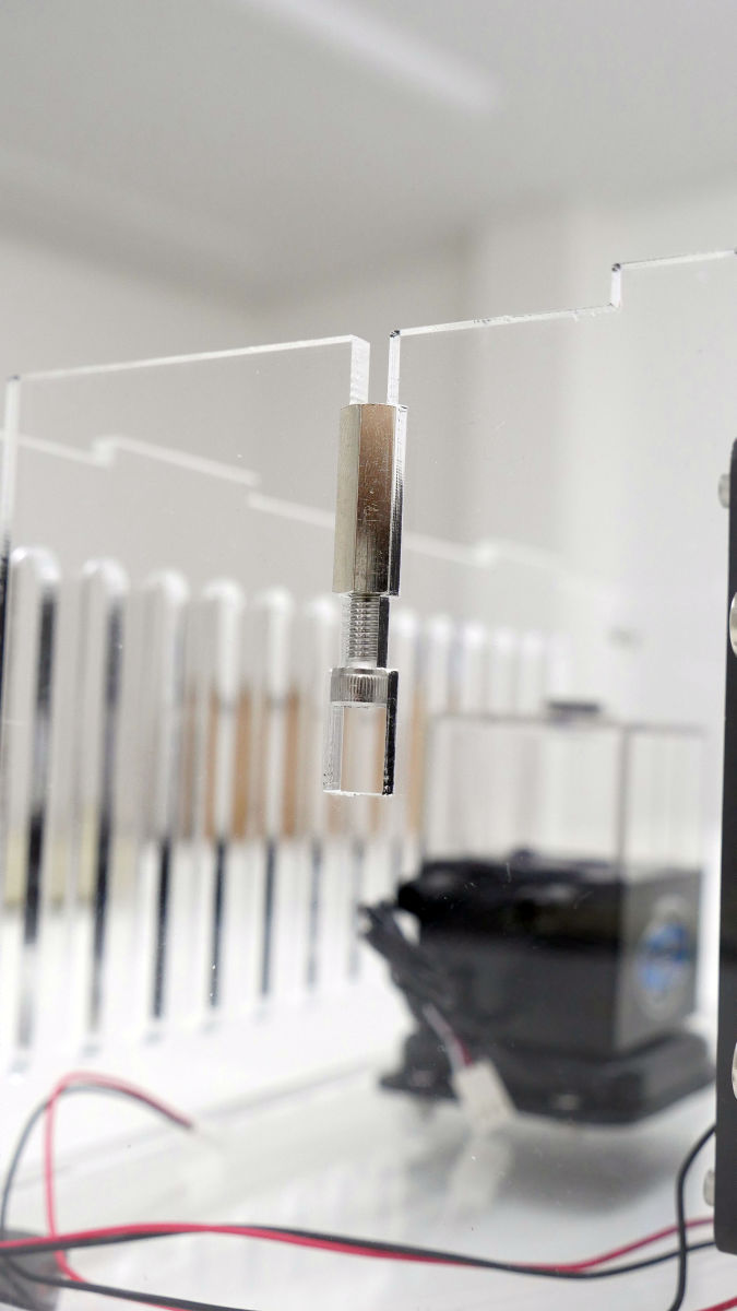
I attached a brass spacer. This is for fixing the top panel.
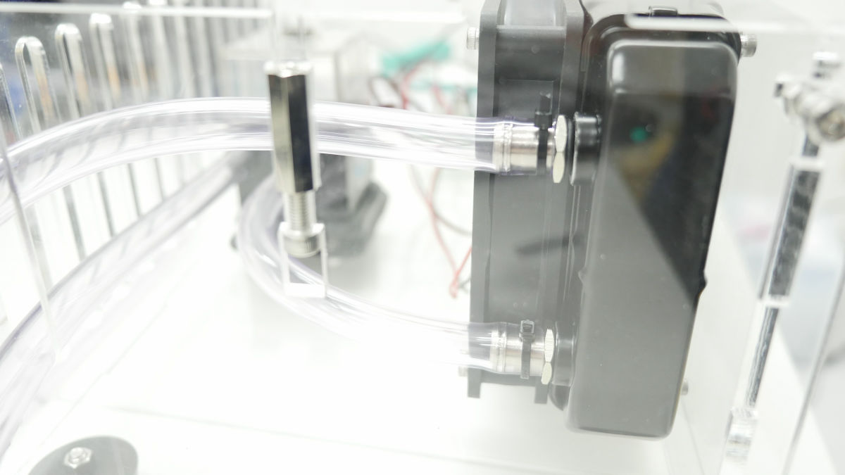
Cut the hose to an appropriate length and connect the radiator and cooling pump.
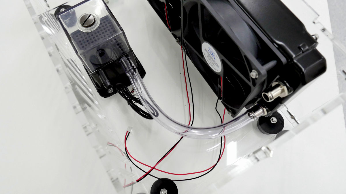
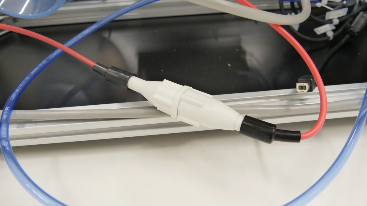
It is also attached to the laser tube. To prevent water leakage, tighten the tip firmly with tie wrap.

While checking the directions of IN (inflow) and OUT (outflow), connect the hose ......
We will also install a flow meter on the way.

Pour water into the cooling pump ... ...
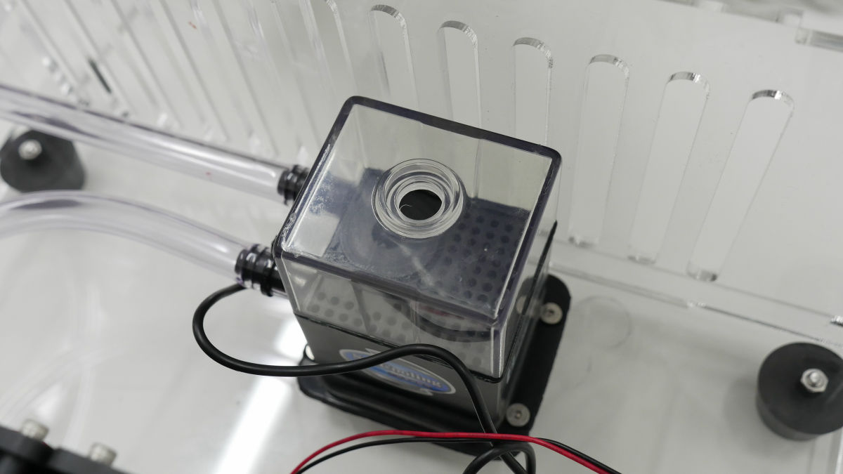
Insert the AC adapter and turn on the cooling pump. If water circulates without leaking water OK.
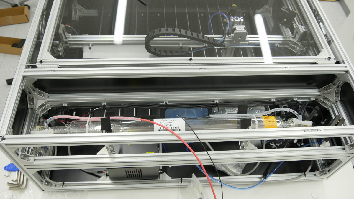
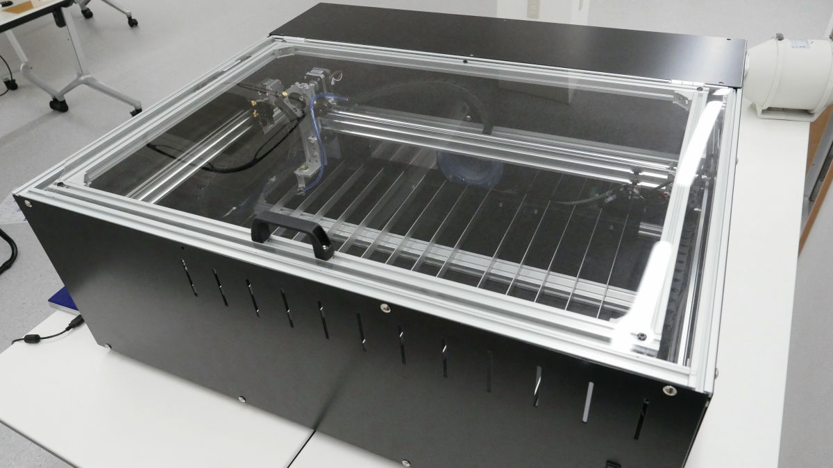
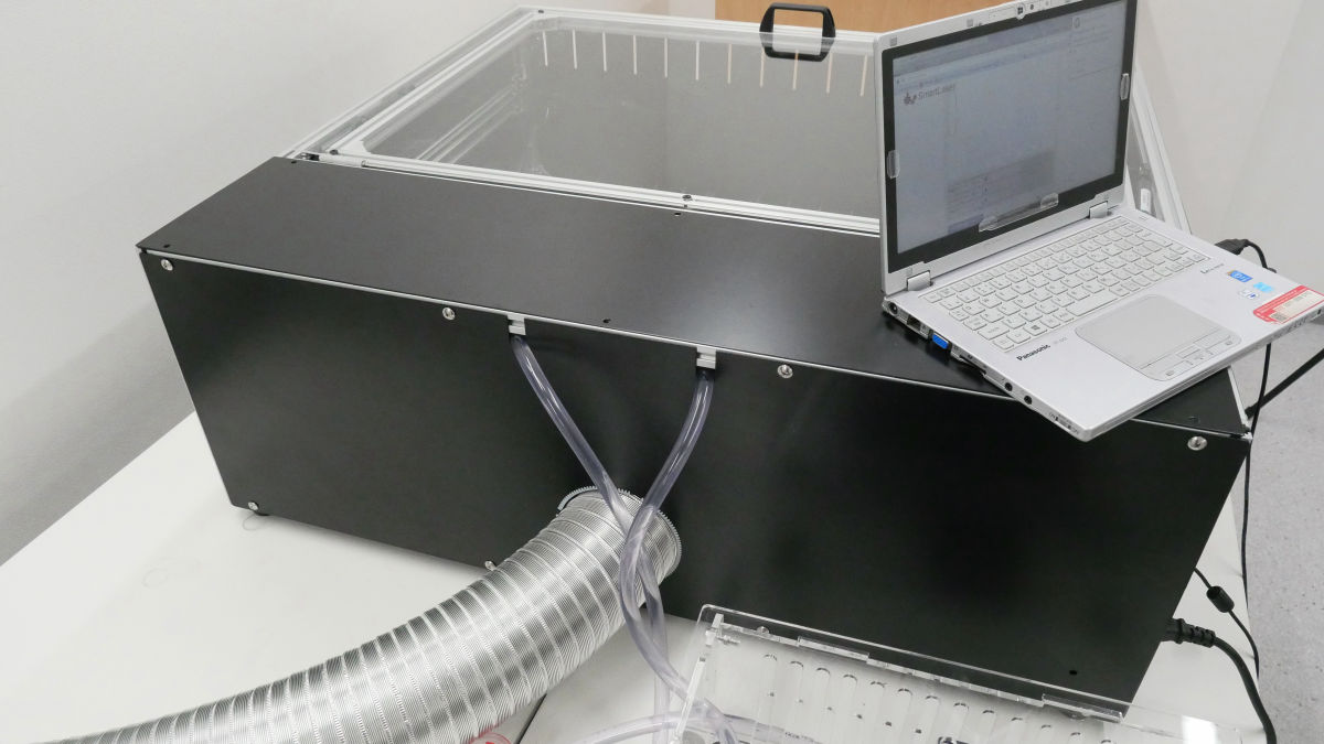
Completion of Smart Laser CO2.
◆ I tried using
Since the laser processing machine & water cooling kit was completed, I tried laser processing at once. First of all, try to "paint" with a laser on a 5 mm thick veneer board (Lauan plywood).
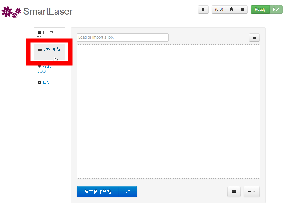
After executing "smartlaser.exe", click "http://127.0.0.1:4444/"To display the program execution screen.
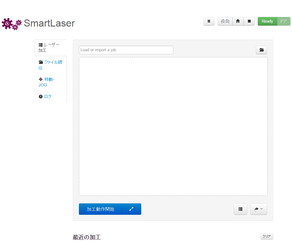
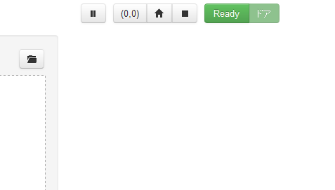
In addition, various icons on the upper right of the screen are "Pause", "Move to Origin", "Perform Home Return", "Stop", "Status Display", "Door Opening Display" from the left.
To read the file, click "Read file" on the left side and specify the SVG file.
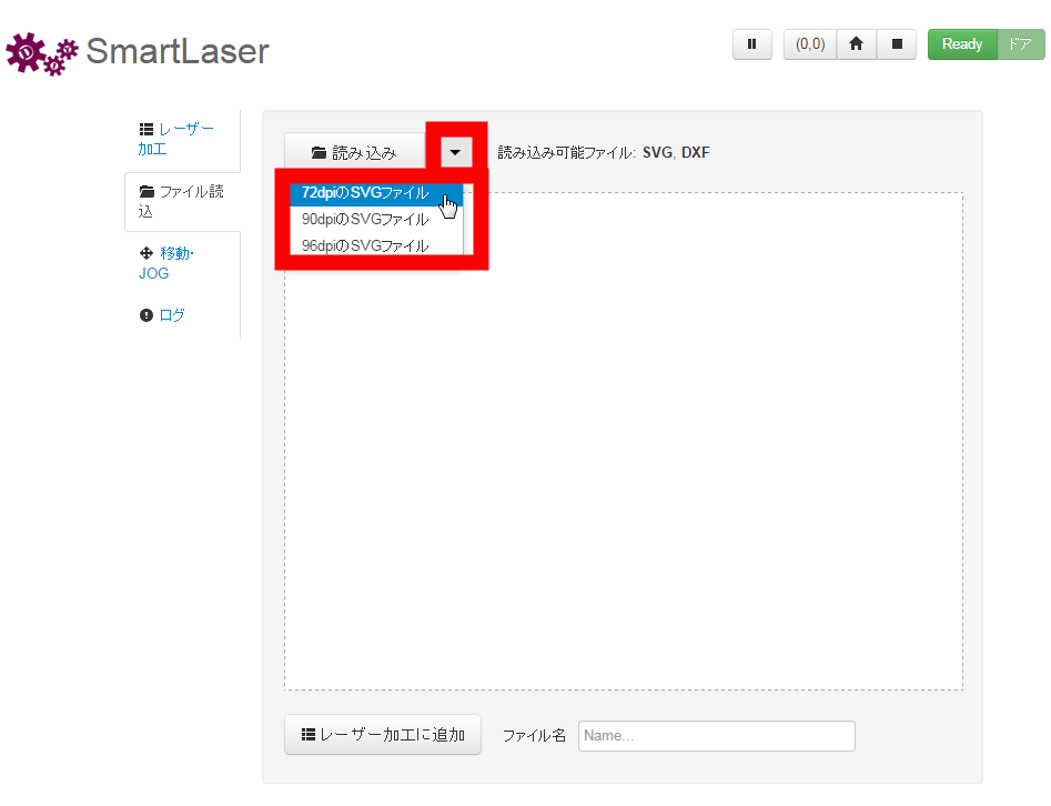
Next, click the format corresponding to the import file from the pull-down menu to the right of "Load".
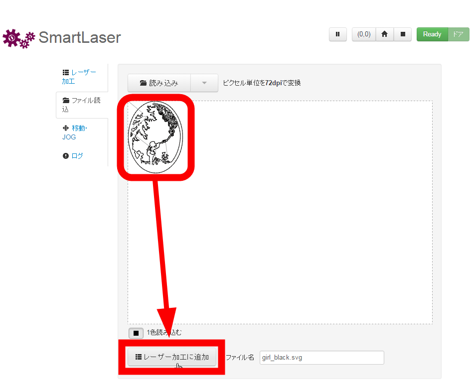
Confirm that the contents of SVG file is displayed and click "Add to laser processing".
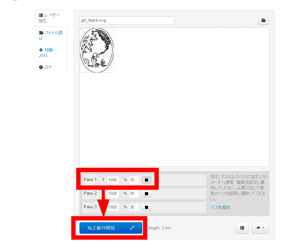
Specify the path, moving speed (mm / min.), Laser output and click "start machining operation", laser machining will start.
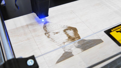
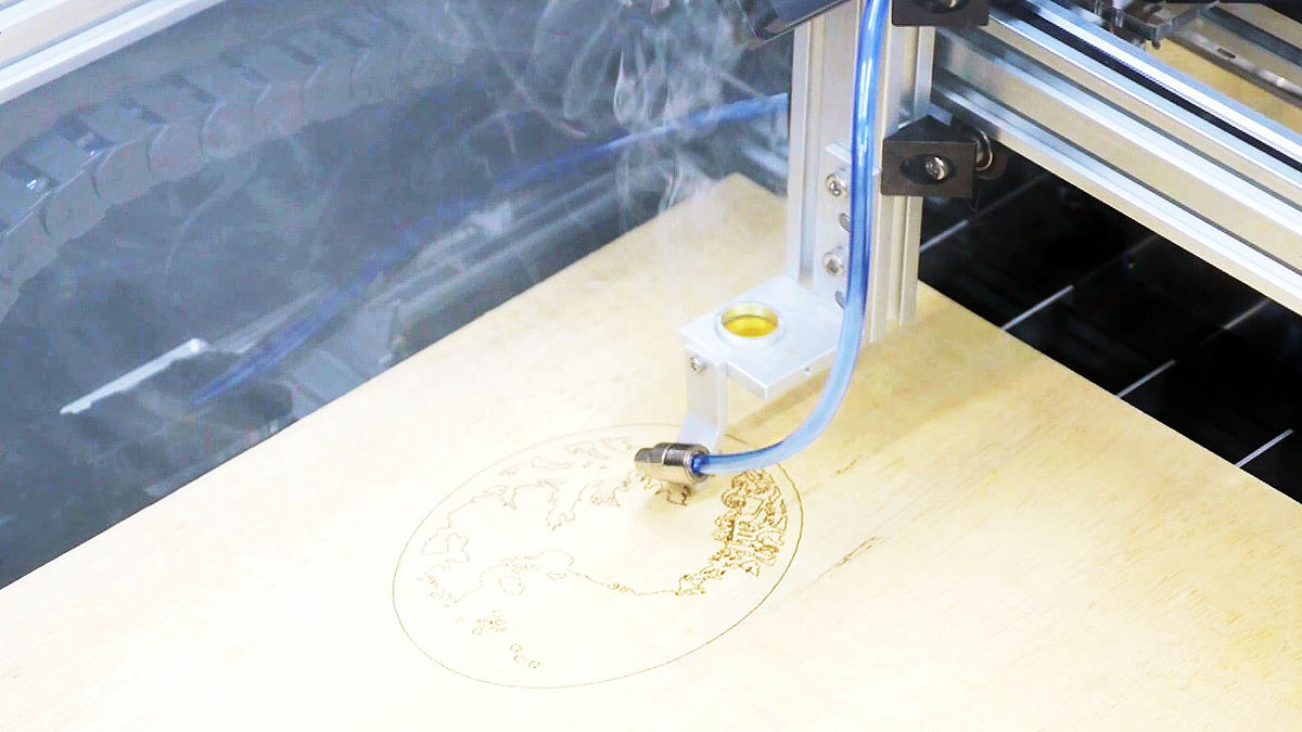
It is like this when carving a picture of a sample program on a veneer board using Smart Laser CO 2.
I tried putting brown on Lauan plywood at the world's largest assembled CO 2 laser processing machine "Smart Laser CO 2" - YouTube
Processing ended in about 2 minutes.
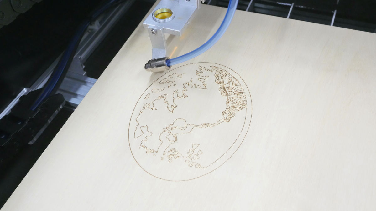
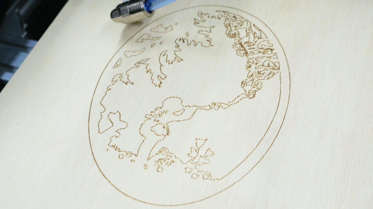
Even at about 30% output, I could paint with burning the surface of the tree.
In addition, Smart Laser CO 2 is a mechanism that does not output laser when the top cover is open for safety. Therefore, you can open the top cover and run the program to check whether the material to be processed is correctly placed in the workspace.
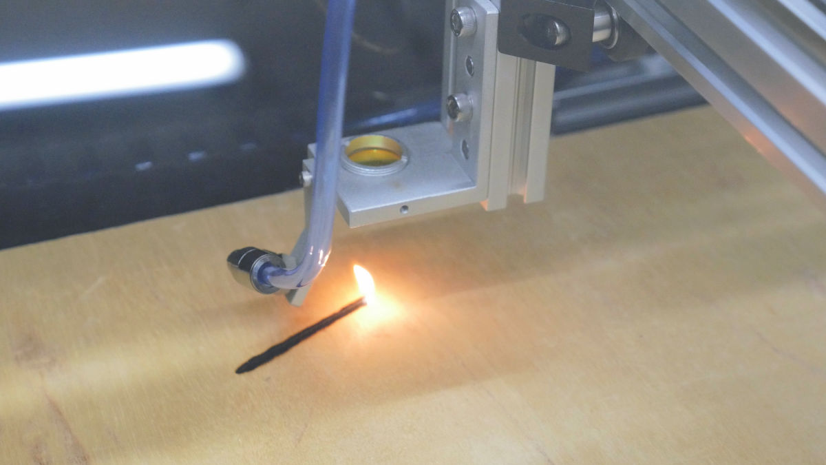
However, raising the output to cut the wood board and slowing down the moving speed resulted in a state where the fire came out from the surface, but it was not possible to dig deeply just by browning along the cut line . When cutting a tree, it seems better to raise the speed of movement and repeat the program and raise the depth by tracing the cut line many times.
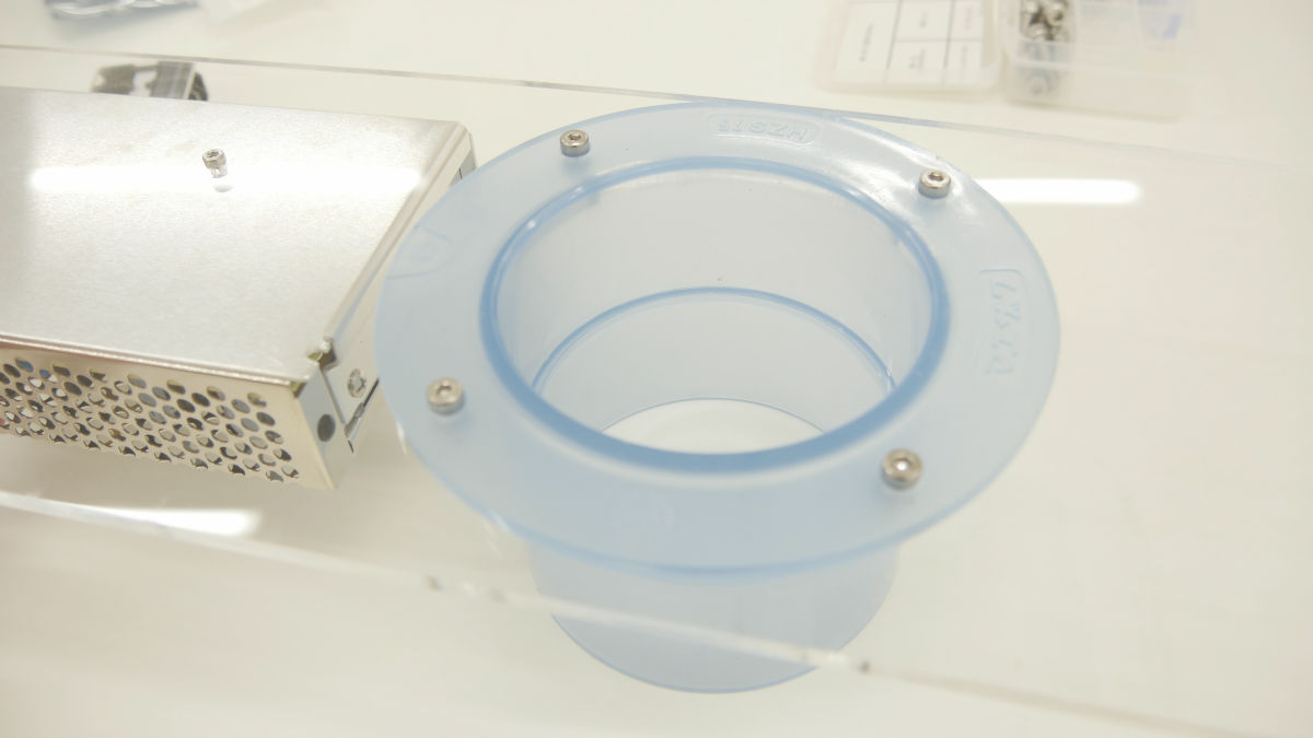
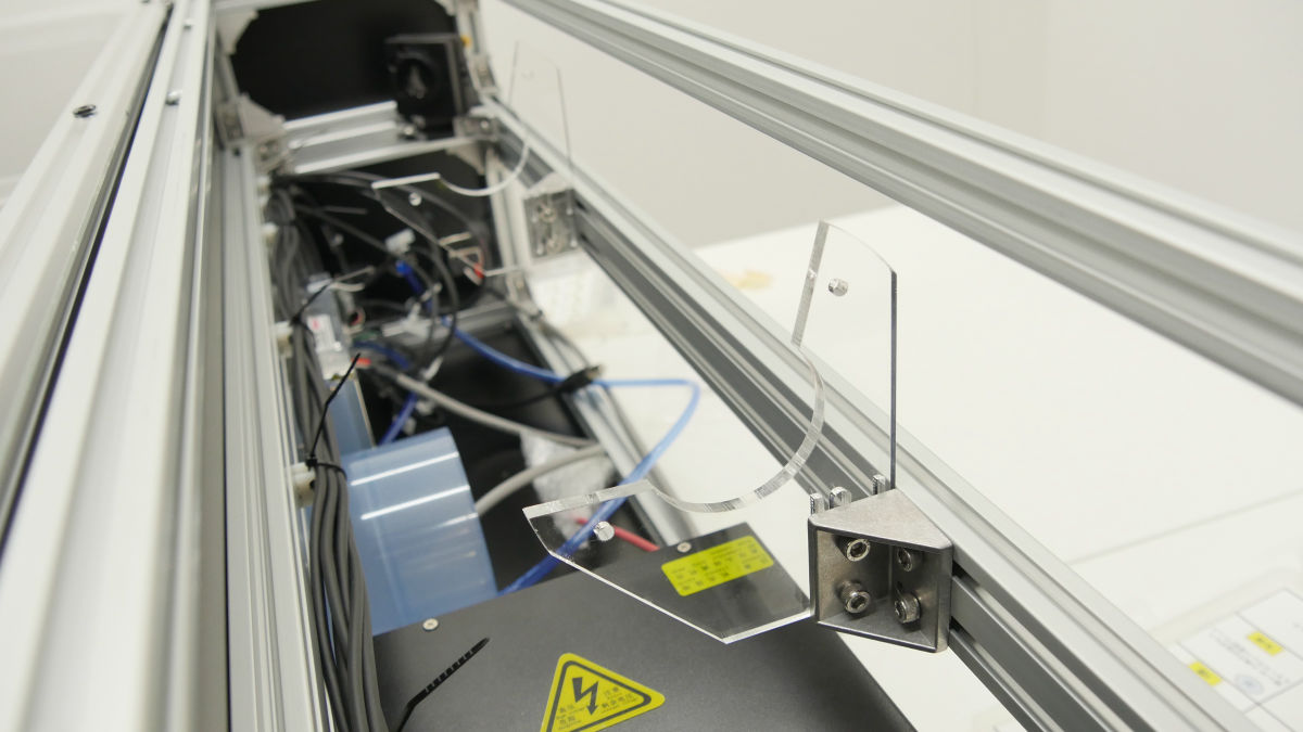
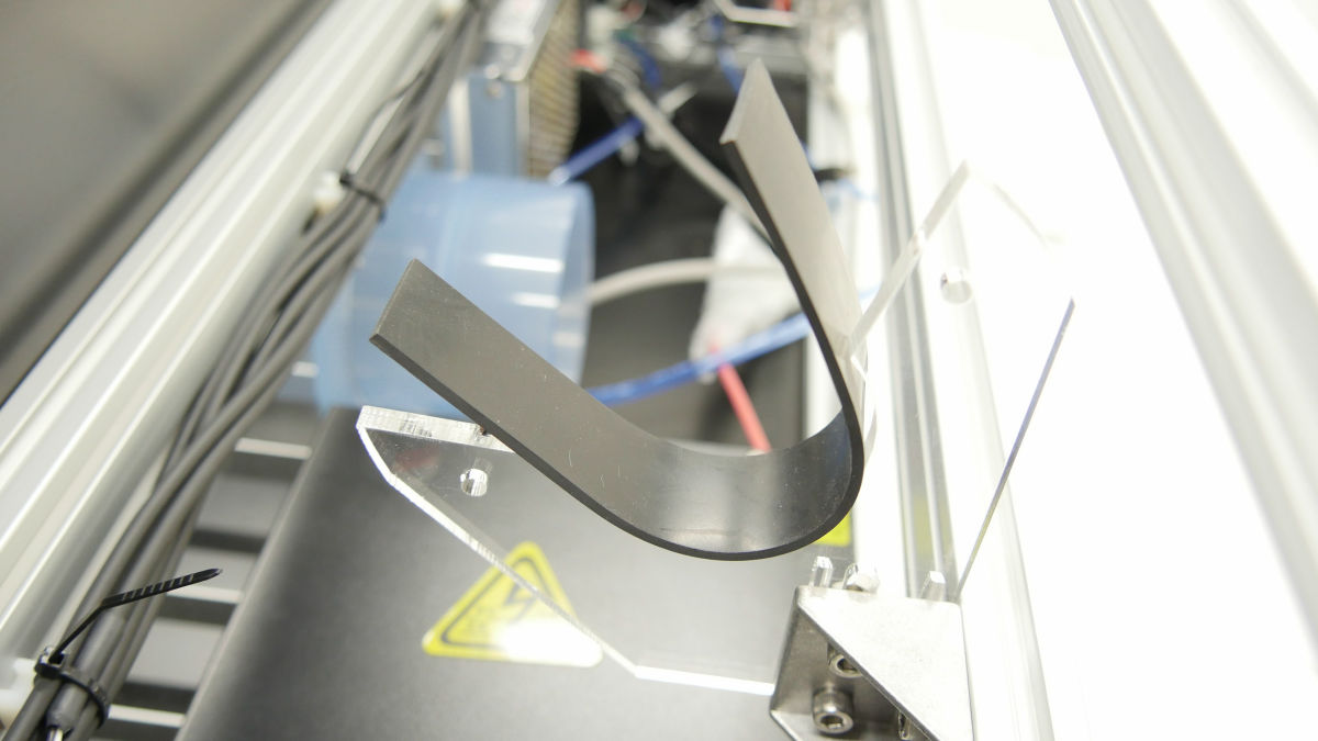
When treating wood with laser, smoke accumulates in the working space, so we will install an exhaust device. Fit the duct hose into the socket ......
Optional exhaust fan kit installed. It is possible to forcibly exhaust the smoke. When treating wood and acrylic, smoke is filled and it is a considerable smell, so it seems better to attach the exhaust fan kit as much as possible.

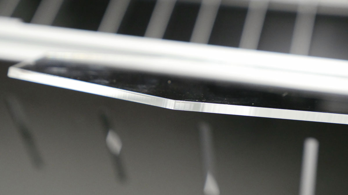
When I tried cutting the acrylic panel, it was easy to succeed. An acrylic board of about 3 mm can be cut without biting.
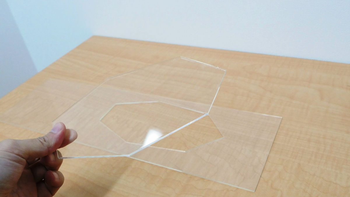
The cross section is extremely smooth. It is a finish that is comparable to commercial laser cutters.
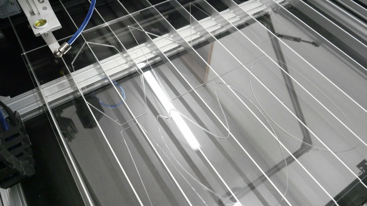
Since the work area of Smart Laser CO 2 is 600 mm × 440 mm, if you use a large acrylic panel, it is also possible to cut out a large number of parts in one stroke.
Smart Laser CO 2 has a high output of 40 W which is comparable to an expensive CO 2 laser processing machine, and the processable range is huge as 600 mm × 440 mm. Processing of wood and acrylic can be done easily. In addition, since special software can read SVG file, it is possible to make cut drawing with software such as Adobe Illustrator.
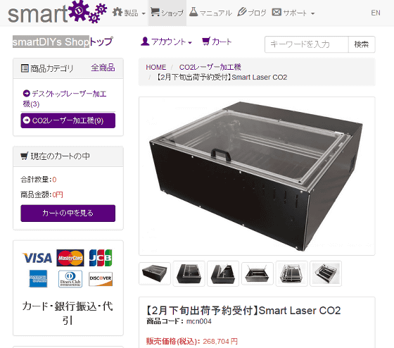
The world's largest assembled CO2 laser processing machine "Smart Laser CO 2" is 248,800 yen (excluding tax), the official online shop "SmartDIYs ShopIt is on sale at. At the time of article creation, it is reservation reception for shipment shipped in late February.
[Receipt of shipment for shipment in late February] Smart Laser CO2 | smartDIYs Shop
http://shop.smartdiys.com/products/detail.php?product_id=752
· Continued
I tried various processing with CO2 laser processing machine "Smart Laser CO 2" which realized output of business level at super price cheap - GIGAZINE
Related Posts: