The projector screen "Kikuchi GRANDVIEW GFP" broke so I repaired it with a 3D printer Report
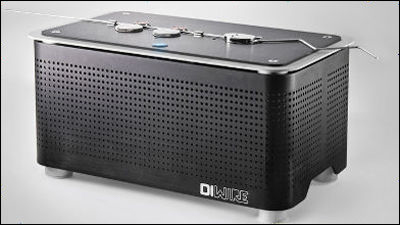
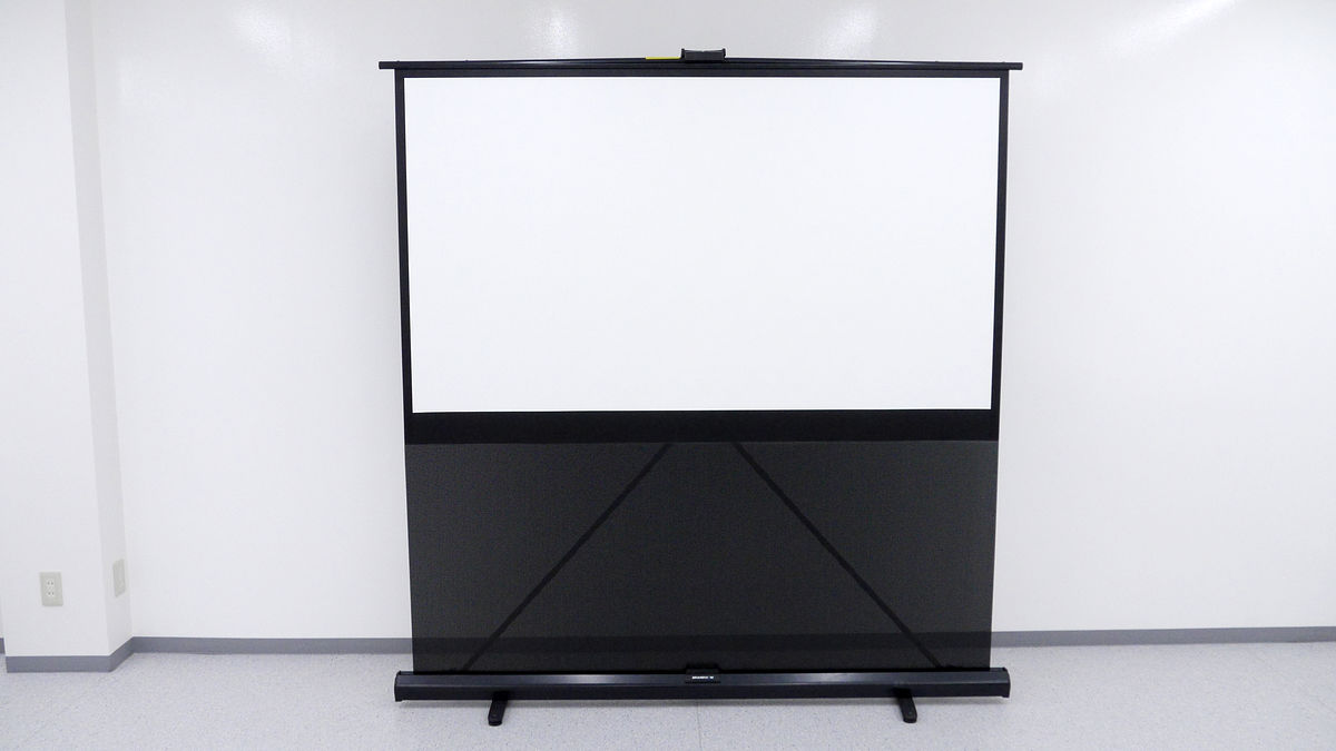
One day, the projector screen that I always use in the editorial department "Kikuchi GRANDVIEW GFPEncountered the trouble that it will not become self-reliant well. When examining the cause, it turned out that a part of the clasp of the frame on the back was damaged, and the two arms were not joined properly. As I looked at the broken parts, I thought "This can be made with the 3D printer of the editorial department ...", so I actually printed the parts and repaired it.
◆ Preparation
First, we identify the broken part of the screen projector.
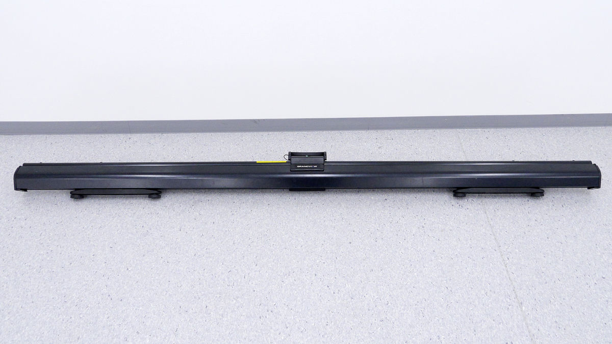
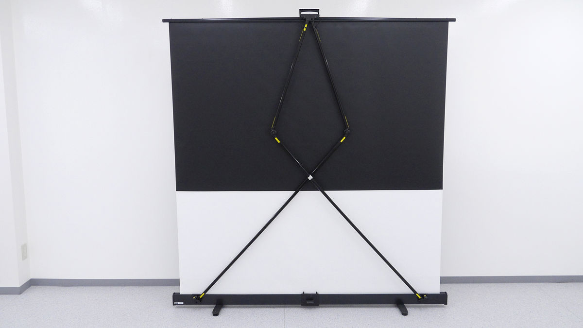
Try to stand the projector and see the back side.
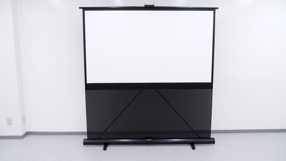
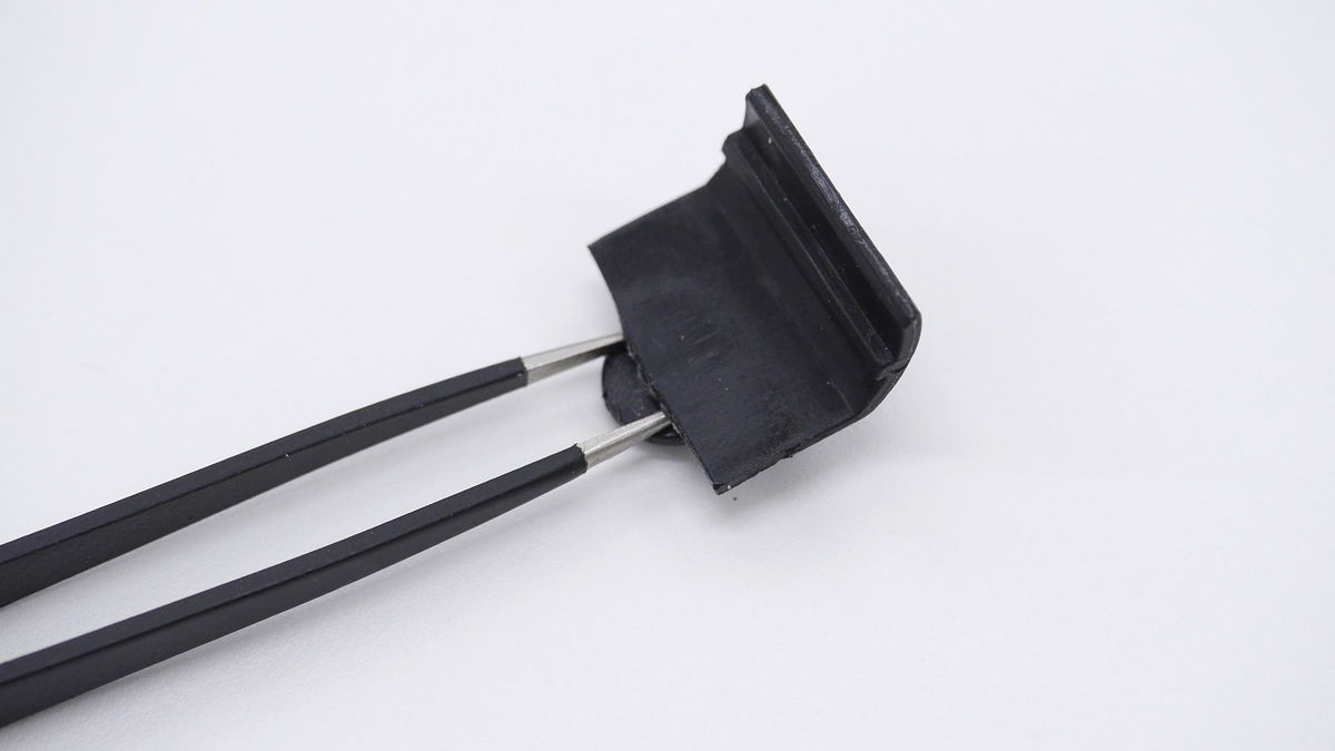
When turning to the back, the metal fittings of the arm obviously go wrong.
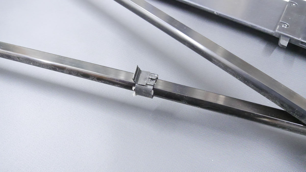
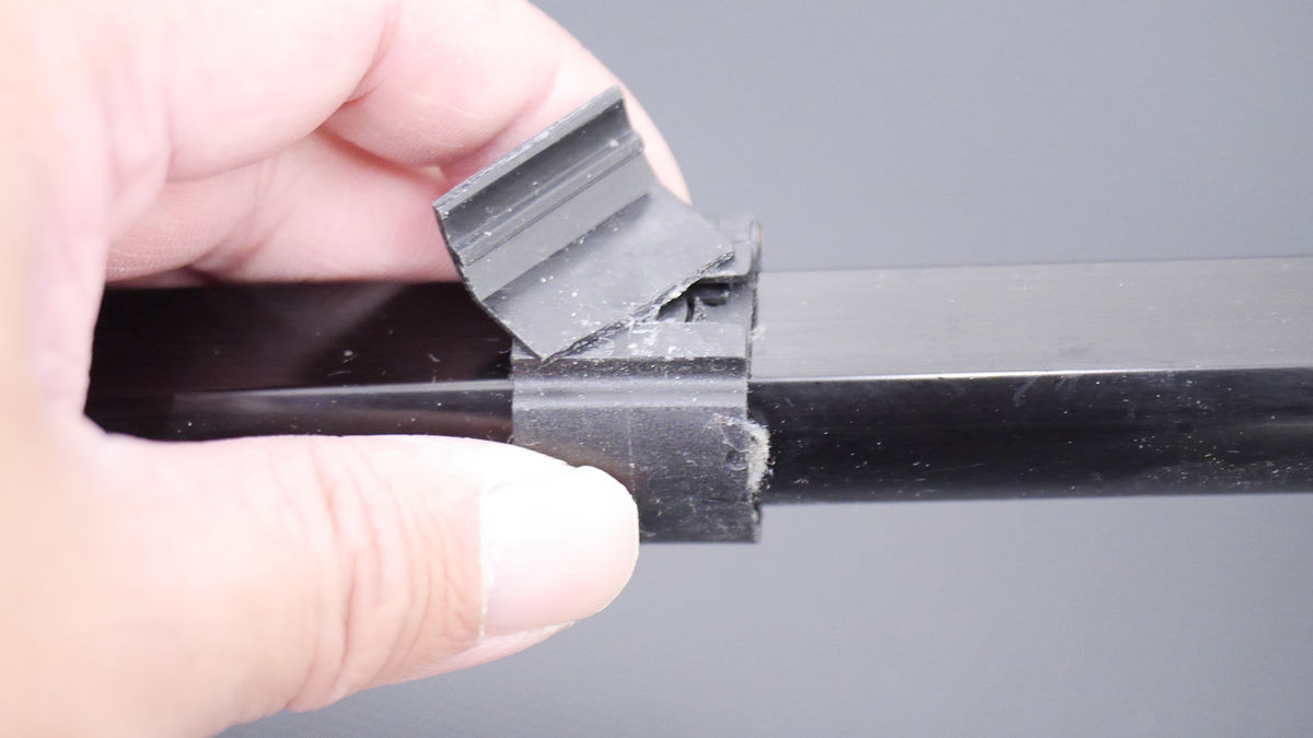
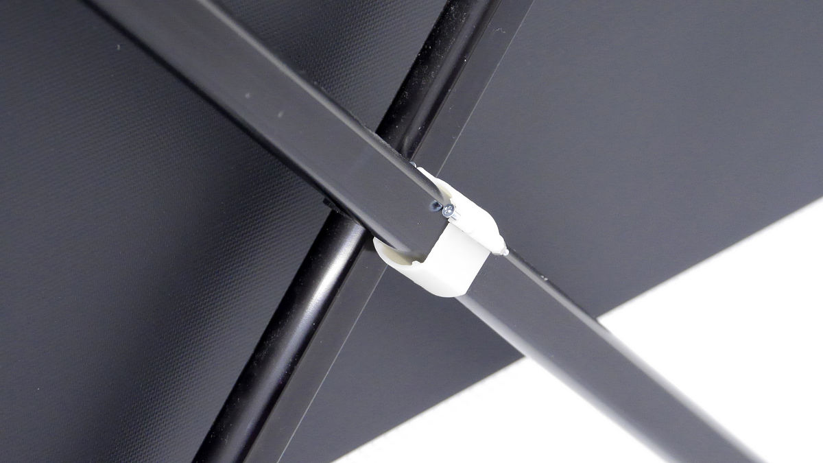
Observing carefully, apparently, the cause seems to be this metal fitting that fixes the cross bar. Part of the part is broken and it is not functioning.

So, try removing the problem part from the screen projector and "printing" with the 3D printer.
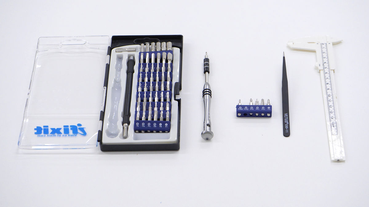
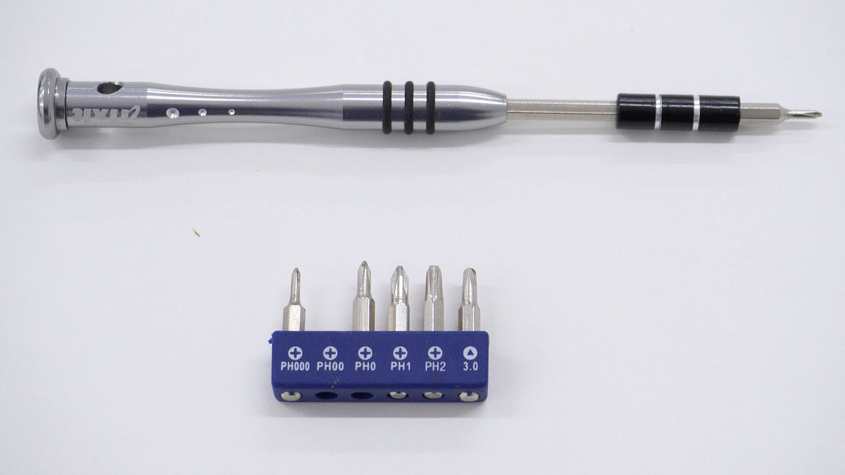
Prepare the necessary tools before starting to remove work. The tool used this time is a set of driver sets, tweezers, vernier caliper.
The fixing bracket in question has two ring shaped partsTapping screwIt was in a state tightened with. Remove the screw using the screwdriver, you can remove the part.
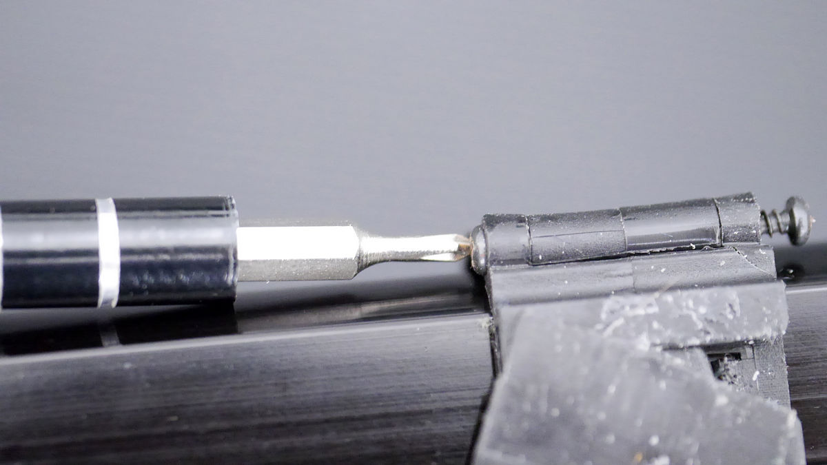
When unscrewing with iFixit's repair set, PH 00 of the Phillips screwdriver was the best.
It will look like this.
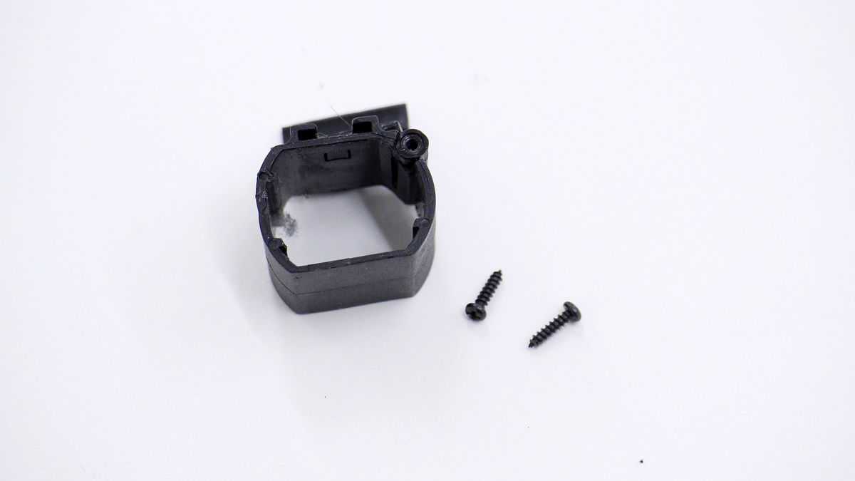
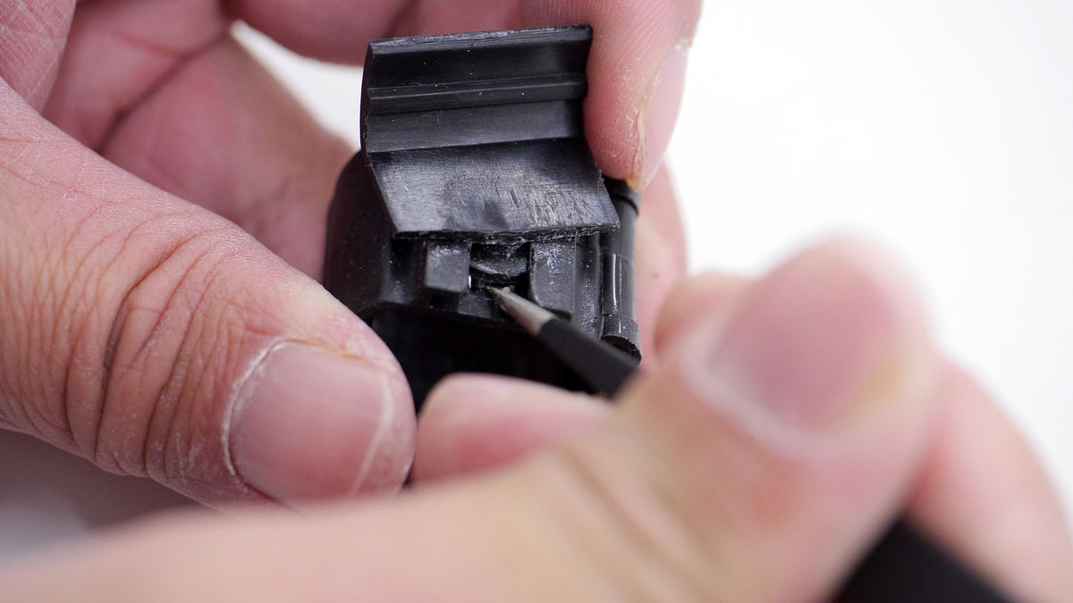
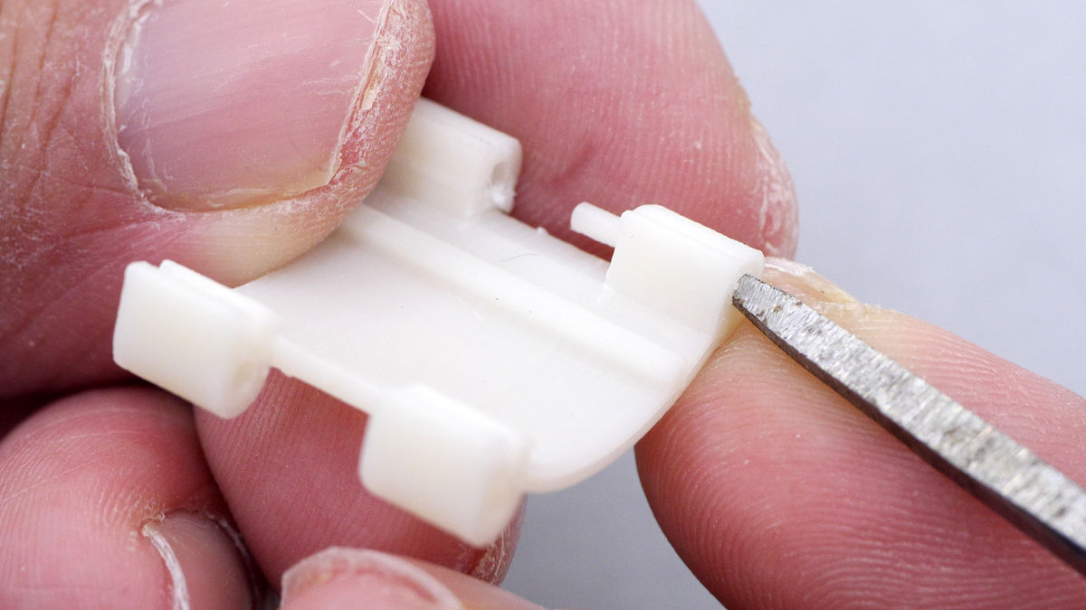
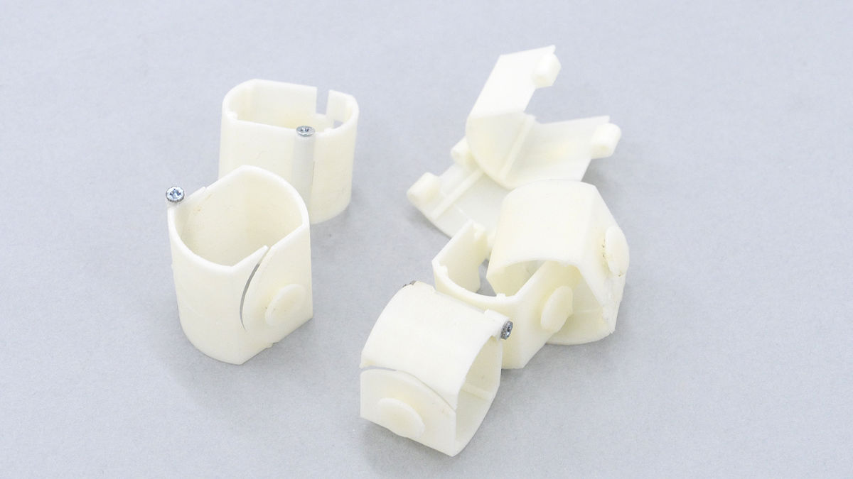
Next, we separate the parts that are breaking away from the parts that are still usable. When detaching parts it is important to use tweezers, carefully remove them while putting strength.
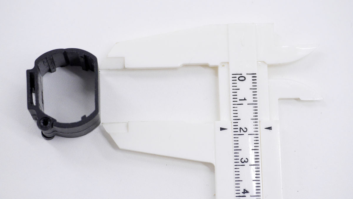
I was able to remove the damaged parts. Originally this is a ring-shaped part, but it has broken in half, and the part that is broken is missing.
◆ Measurement
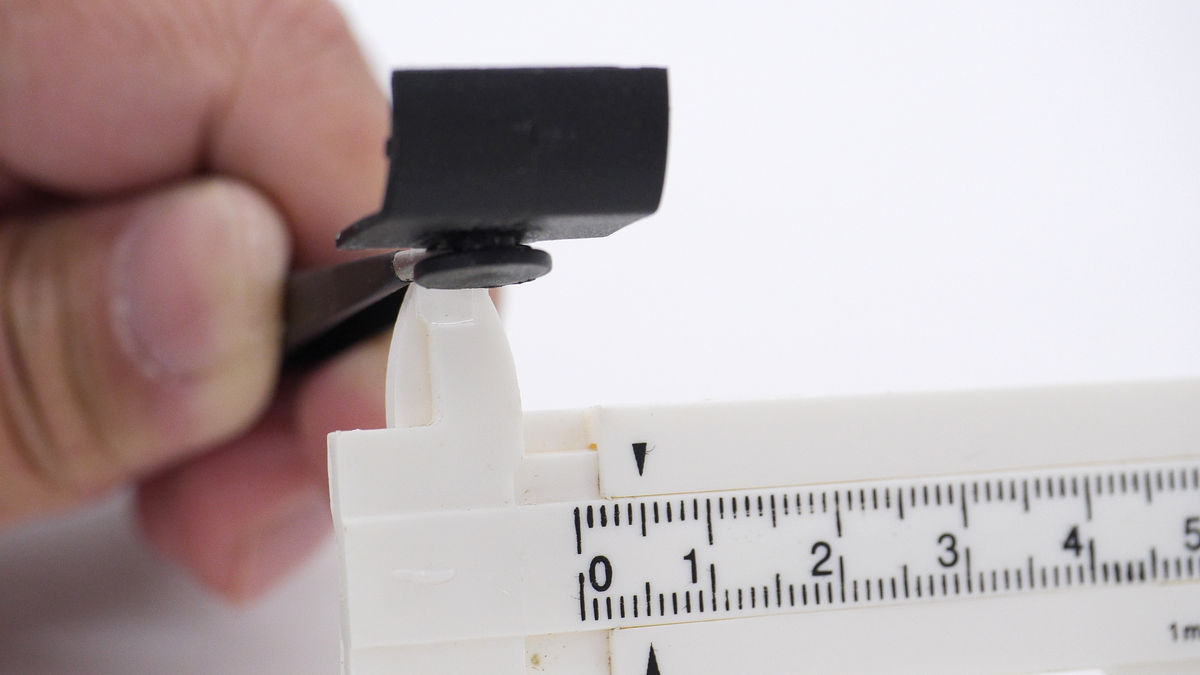
Next we will measure the removed parts with calipers. As most of the parts that had been breaking this time have disappeared, we will design with reference to the parts of the partner that will be paired. First measure the length of the part to be referred ... ...
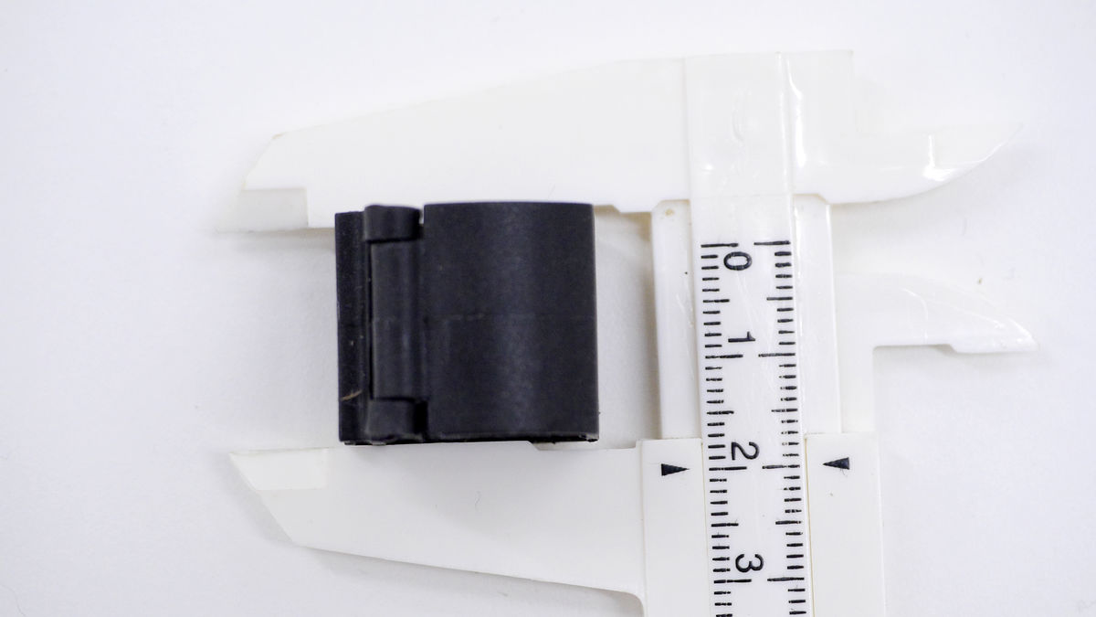
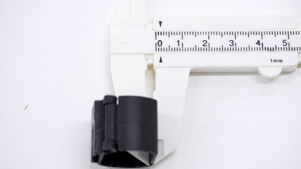
Subsequently the diameter
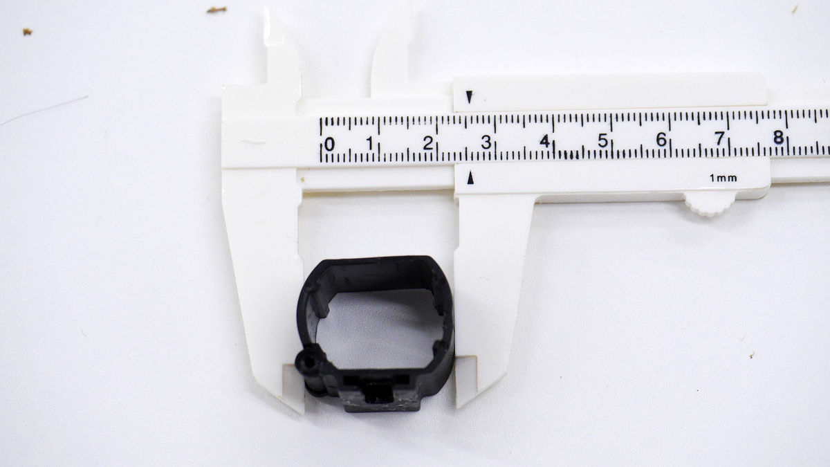
And measure the height.
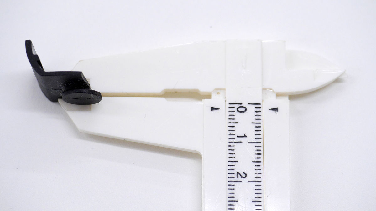
Measure the dimensions of the flat part at this time.
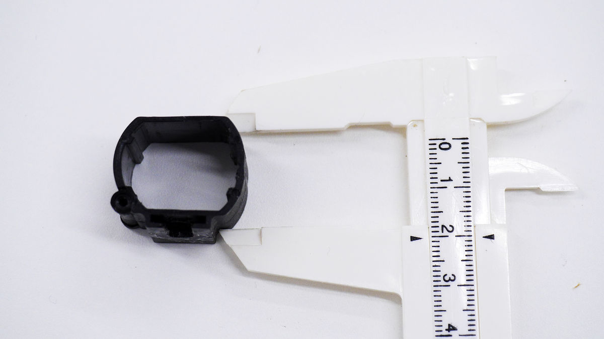
Also measure the thickness of parts.
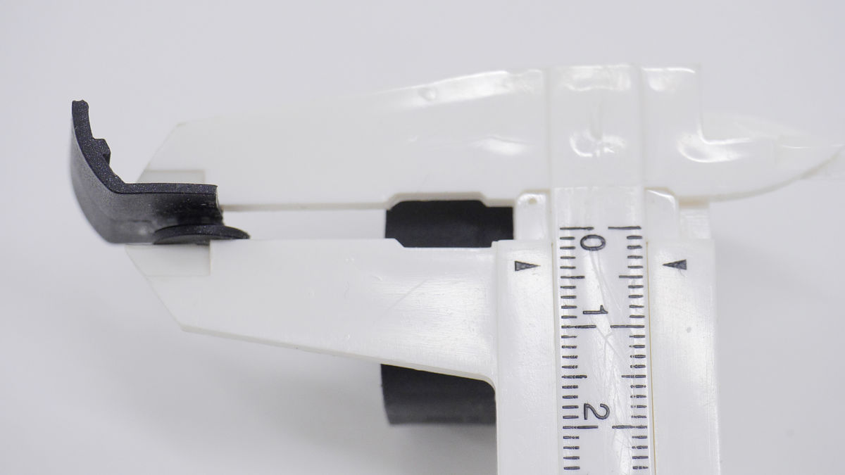
Next, measure the connection part of the broken part. Measure the thickness of parts ...
Measure the thickness of the connection part.
The part that connects the two parts had become narrow grooves that can not enter even the tip of the caliper. When taking measurements in such cases, put the tip of the tweezers in the place you want to measure and scissors ......
If you measure the tweezers width with a caliper, you can investigate the dimensions without difficulty.
The measurement of each part of the part is completed with this. Based on these data, we will design parts to be created with 3D printers.
◆ Designing parts
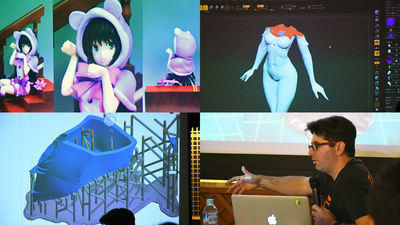
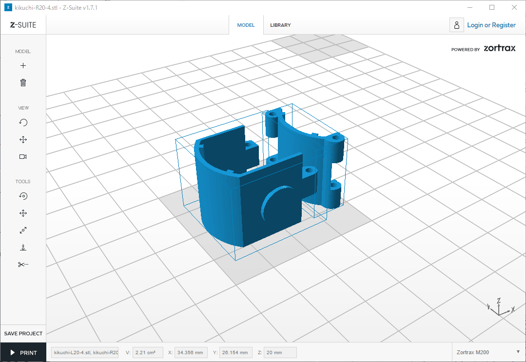
This time, 3D CAD softwareRhinocerosWe will design parts. Although the design procedure is omitted here, as a basic way of thinking, it is designed with no load on parts itself by using two screws. The diameter of the screw can correspond to M2.6 or M2, and if it is a screw of about 25mm ~ 30mm length it can fix it roughly. If you have a special bolt cutter you can fix it more tightly. In addition, when attaching the screw of M2.6, please check carefully the position of the hole and be careful as the part breaks unless you attach it.

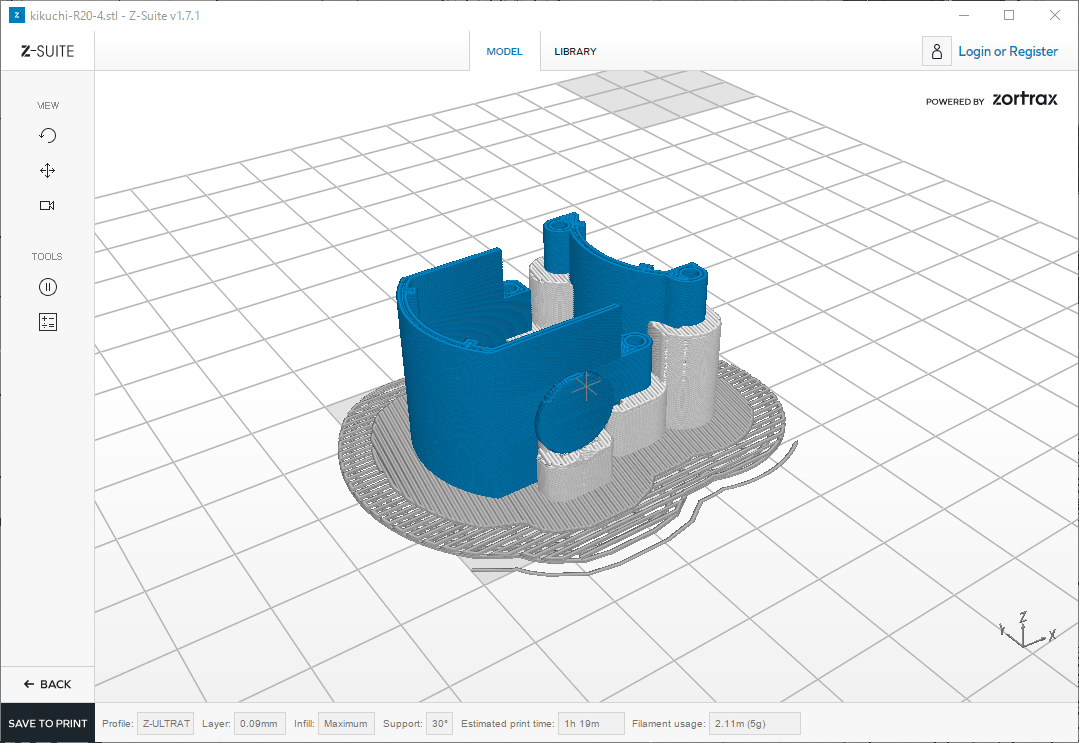
After designing,ZORTRAXConvert 3D data to G code to control the 3D printer using a slicer. In this case to pay attention to "lamination direction", set here in the direction perpendicular to the screw as the part breaks unless you are careful here.
If you can slice like this, you only need to load it into a 3D printer.
◆ Output by 3D printer and assembled
From here, I will actually print parts with 3D printers.
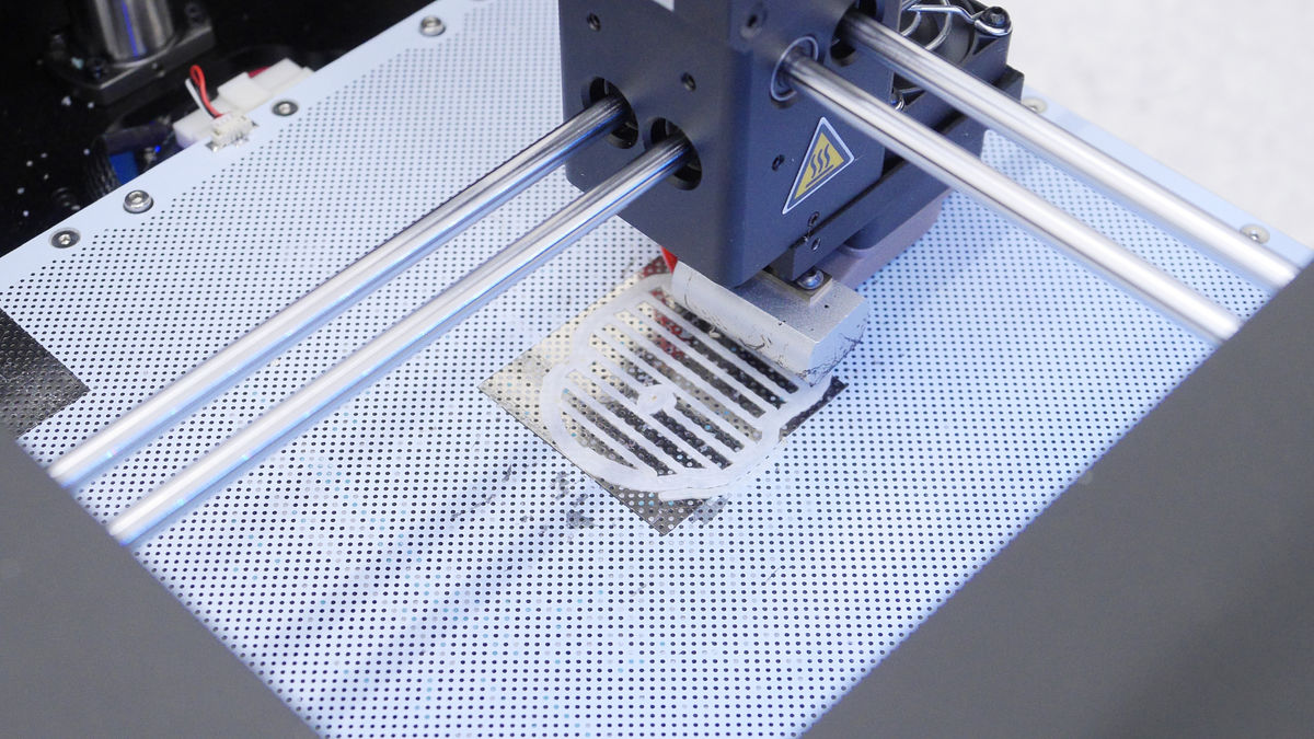
"Raft" as the basis of printing was printed.
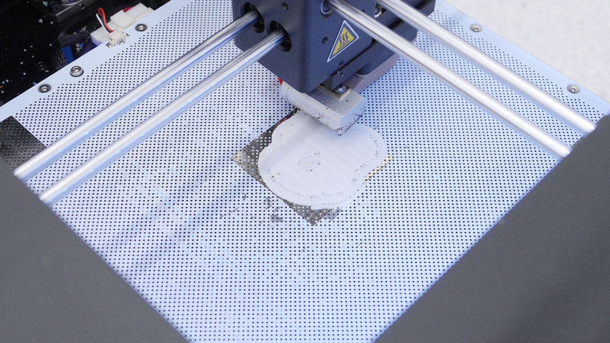
And the parts are gradually formed ...
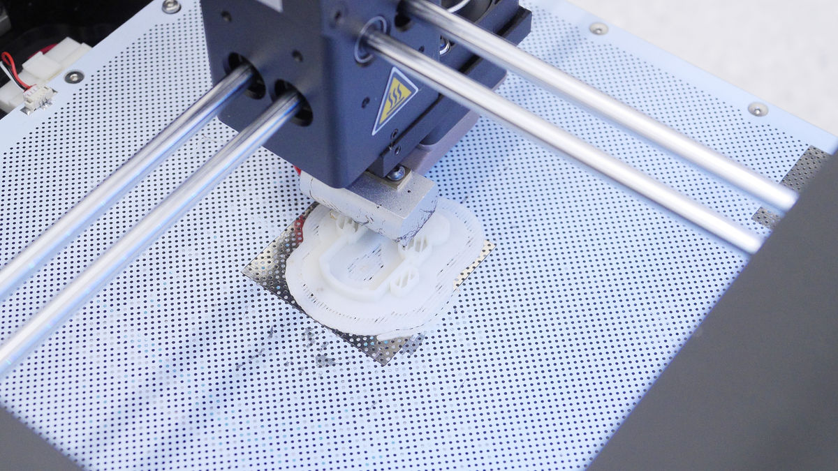
It will look like this when completed.
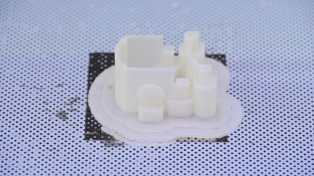
Remove it from the printing stand ... ...

Remove rafts and support. Although you can remove rafts and supports to some extent by hand alone, unfamiliar people can easily remove them using a radio pliers.

And I will use the dust here.
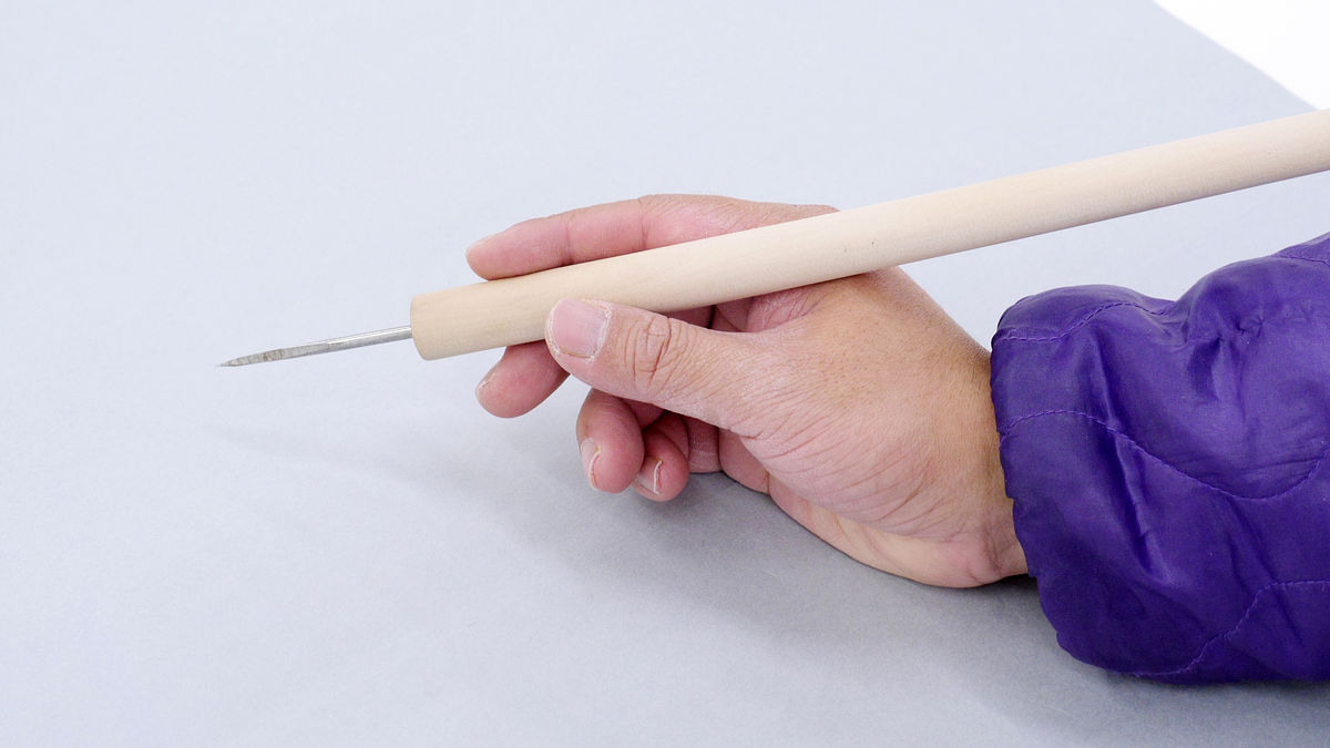
Since the support material at the time of printing is also contained in the threaded hole of the part, please insert the dust or tweezers into the hole and remove unnecessary support material.
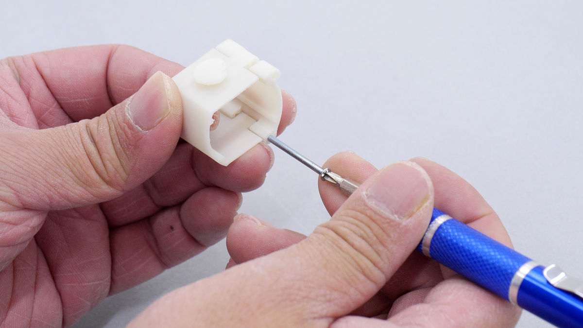
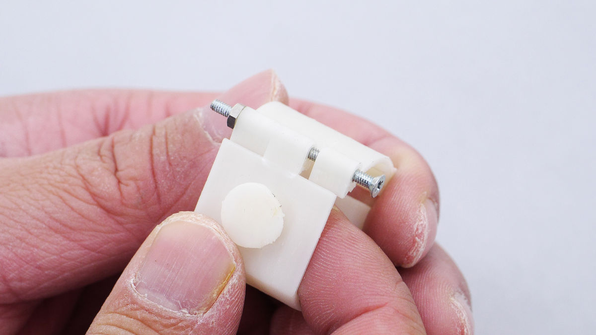
After completing so far, attach screws and fixing nuts to certain holes about the surface of the mounting bracket. When working, be careful as parts will crack and re-print unless you carefully care about the screws. As a trick, if you screw your screws carefully whether the separated screw holes are aligned or not, the parts will not crack.
If you can fix with a nut like this is completed.
◆ Complete with the parts printed on the original screen attached
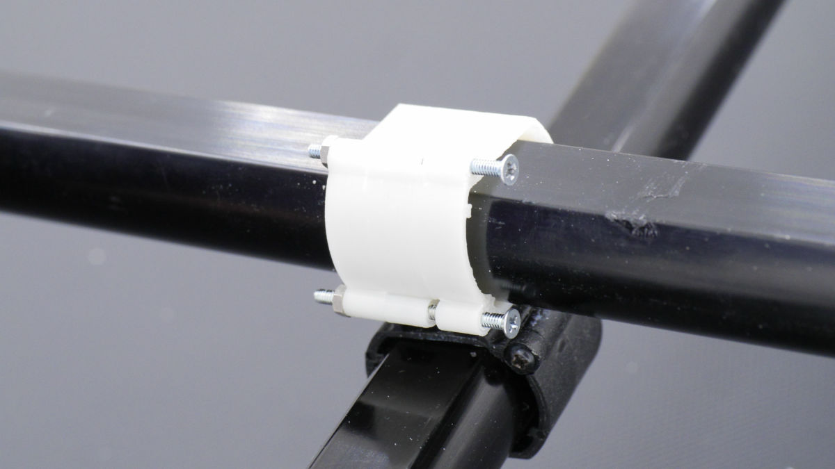
Attach the printed parts to the crossbar of the screen with the broken brackets.

Fix the attachment / detachment part of the part not broken and the printed part.
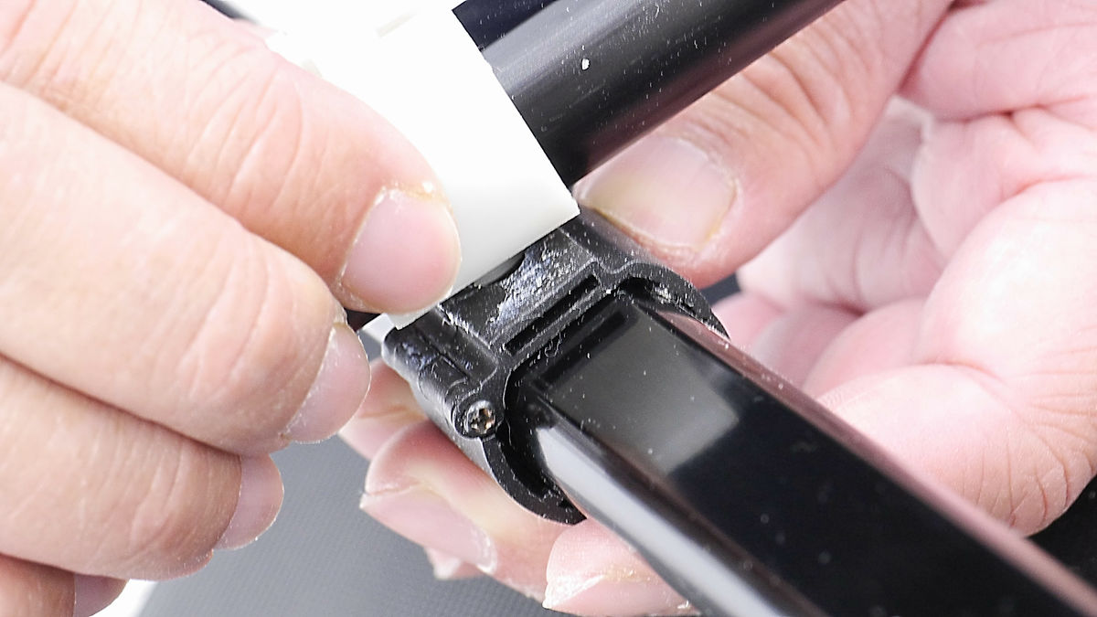
Pass the screw through the unscrewed screw hole and tighten with the nut. Be careful as the parts will break if you do not carefully tighten the screw holes on this side as well.

When completed by saying that it is like this. It should have gone as it is now.

I tried standing the screen projector actually whether there is no problem.
Try looking at it from the back of the screen projector.
It is okay if the metal fittings are securely stopped even in this state. The repair using the 3D printer is now completed.
◆ Try making parts actually
Repairing the metal fittings that support the projector screen with a 3D printer like this one will not work well with a single trial. By repeating trial and error, various points to be improved will be visible, so repeating the trial many times without fear of failure linked to completion as soon as possible. Even with this repair, we have completed several prototypes and completed as follows.
Related Posts: